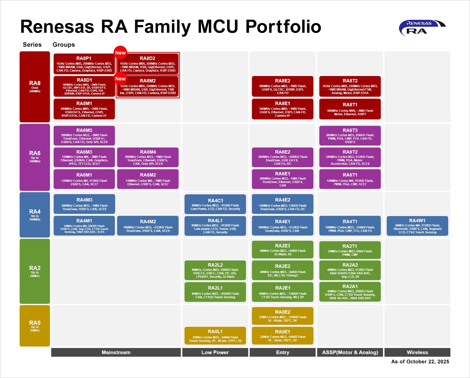
Schema: [c] · Our New 32-bit MCU Lineup: Featuring the high-performance A34G34A (Cortex-M4F, 200MHz, 2MB Dual Bank) and the A31C144 entry-level series. The G43A demo showcases high-quality graphic LCDs powered by the LVGL library for modern appliance UIs. [/c] Vor Ort gab es dann allerdings
, the compact radio modules, equipped with a 1.5 MB flash and 256 KB RAM are based on the new nRF54L15 SoC from Nordic. This chip integrates a 128 MHz arm-cortex M33 processor, an RISC-V coprocessor, and a power-saving 2.4 GHz multiprotocol radio chip. The Bluetooth LE 6.0, Matter, Thread, Zigbee, NFC
704970/6.jpg) Bildquelle: https://www.renesas.com/en/about/newsroom/renesas-launches-64-bit-rzg3l-and-rzg3se-mpus-advanced-hmi-and-iot-edge-systems ### Morse Micro: Wi-Fi HaLow-USB-Dongles starten Die von Morse Micro per se bereits auf der EmbeddedWorld angekündigten USB-Dongles sind ab Sofort
/www.langer-emv.de/de/page/newsletter/51/shielding-measurement-system/170 ### Tektronix MSMU200-2: SMU-Erweiterung für Multifunktionschassis MP5000 SMUs – siehe auch das Demonstrationsvideo unter https://youtu.be/x-xZC5Nx004 – gehören mit Sicherheit nicht zu den weit verbreiteten Laborgeräten
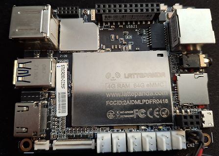
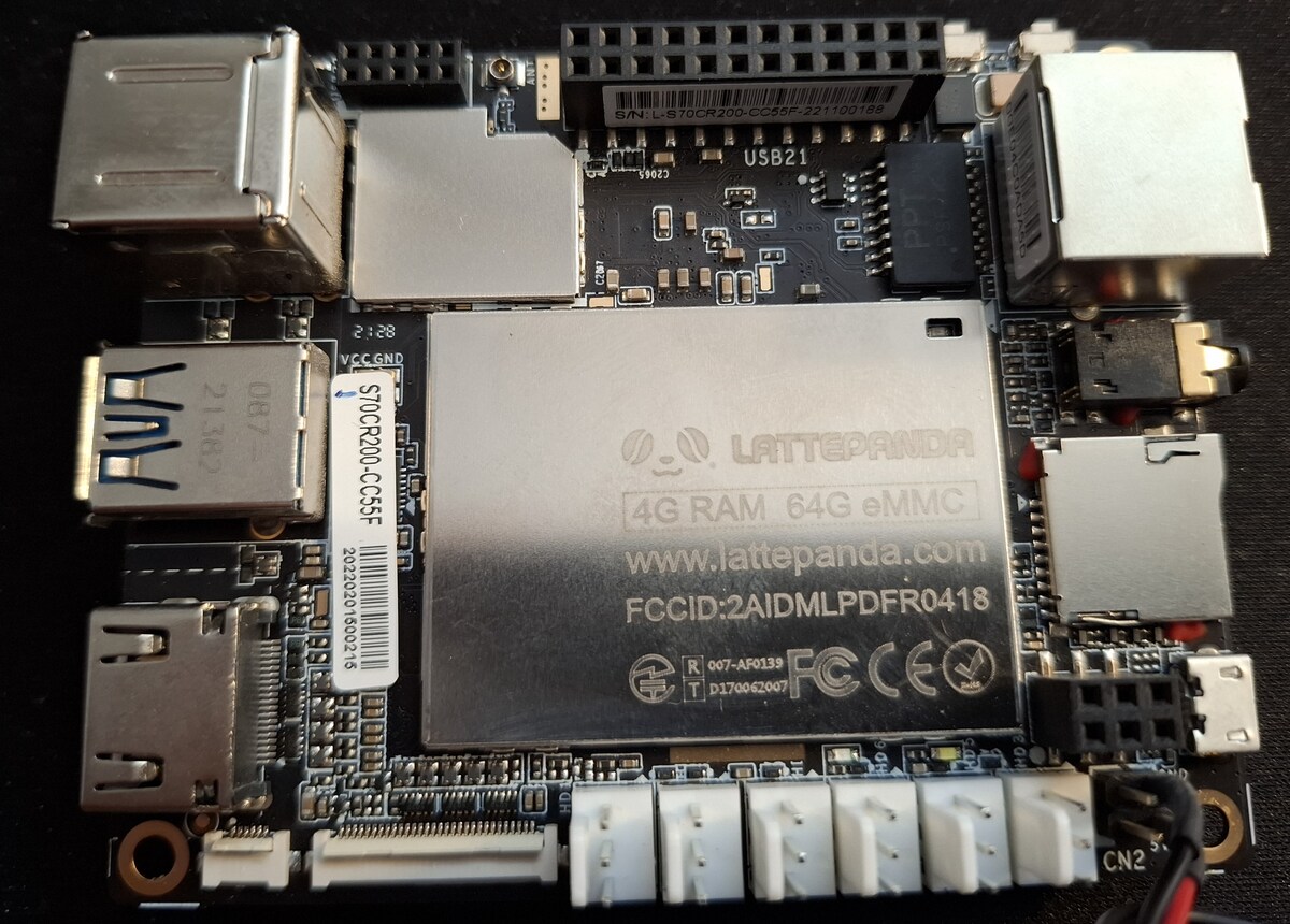
Z8350 Quad Core, 2M Cache, up to 1.92 GHz Operation System: Pre-installed Windows 10 Ram: 4GB DDR3L Storage Capability: 64GB GPU: Intel HD Graphics, 12 EUs @200-500 Mhz, single-channel memory One USB3.0 port and two USB 2.0 ports WiFi and Bluetooth 4.0 Built-in Arduino Co-processor:
ISO, Short, Plus V V 9 3 S_3 D_5 9 8 0 3 S_3 D_5 9 4 NEG+2.5V: ISO, Short, NEG 6 6 8 4 0 1 * 5 AUSH/L: symmetrisch, Not-Aus bei OT,OV und UV 3 W 7 W 7 1 1 C 1 6 D 8 D 8 6 R R C 7 0 5 7 8 R 1 4 Q1 C Q3 9 3 50V TPH2R506PL,L1Q 6 TPH2R506PL,L1Q 10 2 C 11 4 V 1 4 G D_1 5 1 4 G D_1 5 12 D 3 D_2 6 C6 C D_2
generated by the MPX circuit. It combines the left and right channel signals in the following way: m(t) =[L(t) + R(t]+[L(t) − R(]cos( πft +θ2 ) +αcos( πft +θ ) + d(t)cosπ ft +θ3) 0 0 0 Here, L(t) and R(t) correspond to the audio signals on left and right channels respectively, f = 19 kHz, θ is the initial
Current Loop:(-3dB)2KHz (Typisch) • Bandbreite Speed Loop: 500Hz (Typisch) • Bandbreite Position Loop: 200Hz (Typisch) • Parameter können via RS232 zum PC übertragen werden. • Einstellungen über DIP-Schalter oder Software. 2 • Überstromschutz, I T-Motorstromüberwachung, Über- und Unterspannungsschutz, Überhitzungsschutz
less Certification UL248-14 (File No. E167588),TUV (Certificate No. J9650637) UL 50 A at 36 VDC , 200 A at 48 VDC , 300 A at 25 VDC , 80 A at 62 VDC Rated Breaking Capacity This value is the maximum voltage can be cut off by fuse. It doesn't represent the operational voltage of the heater. Rated Voltage
& Anti-static coating Sync Frequency Horizontal: 30.0-96.0kHz, Vertical: 50-160Hz Video Bandwidth 200MHz dot clock H RecommendedResolution 1280 × 1024 at 85Hz I L Input Connector D-Sub mini 15pin G E Plug&Play VESADDC1/2B™ Input Sync Signal Separate sync: TTL, Positive or Negative Input Video Signal
is switched from “L” to “H”, CO becomes “L”. 2. Overcharge Timer Reset Operation When an overcharge release noise that forces the voltage of one of the batteries temporarily beloCUVis input during CU from when V CU is exceeded
Jetzt wäre meine erste Idee, einfach einen größeren MOSFET mit einem größeren Pad zu verwenden. Der RJ1L04BBGTL1 sieht vielversprechend aus. Aber deshalb die philosophische/grundsätzliche Fragen: Die MOSFETs mit dem großen thermischen Pad und insgesamt kleinen Bauform (3mm x 3mm) scheinen "state-of-the-art
www.infineon.com/part/ISG0614N06NM5H Wenn du auf der zweiten Lage im geringen Abstand (etwa 100-200µm) sowieso eine Massefläche hast, musst du dir auch nicht so viele Sorgen machen, dass eine große Fläche beim geschalteten Knoten deutlicher abstrahlen würde. Du hast da schon ein bisschen Spielraum
temperature characteristics are minimized when the d 100° IL300 is used as a servo linear amplifier. e 0.6 l m Figure 2. Servo photocurrent vs. LED current o 0.4 N 300 1 N 0.2 A 250 - 0°C 0.0 n 25°C .1 1 10 100 e 200 50°C IF - LED Current - mA u 75°C o Figure 4 presents the Normalized servo gain, NK1(I , T
C N A R 2.8 z 2 R H 2.0 C ( MAX. A 1 Y 2.6 5.5V Q m P F 1.0 (/ 0 P K 0.8 F S 2.4 C 0.6 R–1 R 5.0V L f E C 0.4 –2 W 2.2 TYP. P –3 2.0 4.5V 0.2 –4 MIN. 0.1 –5 1.8 –50 –25 0 25 50 75 100 125 10 20 40 60 80100 200 400 6001000 0 1 2 3 4 5 o AMBIENT TEMPERATURE (C ) CLOCK CAP (pF) APPLIED V REF/2 (V) Logic
DB3 DB2 DB1 DB0 R L7 L6 L5 L4 L3 L2 L1 L0 0 C6 C5 C4 C3 C2 C1 C0 0 Figure 5 Status Read Instruction Start Oscillation (R00h) The start oscillation instruction restarts the oscillator from the halt state in the stanAfterode
22 MQ 10 pF 4,7 pF Eingang der Phasenkomparatoren. Wie Soil keine Teilung erfolgen, so wird die 130-200 kHz 220 kQ 22 M Q 10 pF - vorstehend bereits beschrieben, verfugt der Brücke BR 11 eingelotet, womit die Aus- 200- 350 kHz 150 kQ 10 MQ 4,7 pF 4,7 pF CD 4046 Ober 2 unterschiedliche Phasen- gangsfrequenz
RPROG=1.3KΩ, V BAT rising 2.8 2.9 3.0 V V TRHYS Trickle voltage hysteresis voltage RPROG=1.3KΩ 150 200 250 mV V UV VCC under voltage lockout threshold ● VCC from low to high 3.5 3.7 3.9 V VCC under voltage lockout V UVHYS hysteresis ● 150 200 300 mV VCC from low to high 100 140 180 V ASD VCCV BAT lockout
Bandwidth:(-3dB)2KHz (Typical) • Speed Loop Bandwidth: 500Hz (Typical) • Position Loop Bandwidth: 200Hz (Typical) • Parameters to download via RS232 to PC. • Users can define subdivisions via external Dial-up switches or via software. • Over-current, I2T-motor-current-observation, Over-voltage, Under-voltage
HoJ=JEon=l ,EH5ECn=l OKJpKJ O.. Dual-in-line A signalOFF )ʢ6AHmEn=l )—+ʣ▯ PackageType ON +lo?FMEIA ON B signalOFF O.. TM *ʢ6AHmEn=l *—+ʣ▯ TACTSwitch O N ON C signalOFF O.. ON )ʢ6AHmEn=l )—+ʣ Custom- +oKnJAH-?lo
Hallo Zusammen, ich habe hier eine defekte Allpowers S200-Powerbank bei der ein 5V-Spannungsregler kaputtgegangen ist. Mit dem Spannungsregler ist auch der Prozessor CH549L kaputtgegangen-wird bei Betrieb glühend heiß. Nachdem ich eine SMD-Lötanlage habe
original Atmel AVRISP mit GND verbunden. Der 10-polige Anschluss wurde von der Firma Kanda beim STK200 verwendet und ist deshalb auch als „Kanda-Standard“ bekannt und war zur Zeit der STK200 Programmieradapter relativ weit verbreitet. Die Anschlussbelegung über einen 6-poligen Stecker stammt von Atmel
10 problemlos funktionieren, egal ob unter Arduino IDE, Atmel Studio oder Bascom. Parallelport. STK200-kompatibel. Fast alle erhältlichen Parallelport-Programmieradapter, u.a. auch der hier im Shop angebotene, sind kompatibel zum Programmer des STK200 / STK300. Schaltbilder für STK200 und kompatible
de l'air très élevée peut réduire l'isolation et mener à des électrocutions mortelles. Lors de l'utilisation de machines à fumée il faut faire attention à ce que l'appareil ne soit jamais exposé directement
2) V ee= 5 v. IF= 10 mA 40 110 µcd hp Wavelength at Peak Emission 640 655 670 nm ~;\ V ee= 5 v, V L E o= 4V Spectral Bandwidth 20 nm V1H High-Level Input Voltage 2 v V1L Low-Level Input Voltage 0.8 v V1K Input Clamp Voltage V ee= 4.5 v, 11 = -1 2 mA -1 .5 v l1H High-Level Input Current V ee= 5.5 v, V1=2.4 V 150 µA l1L Low-Level Input Current V ee= 5.5 v, V1=0.4 V -1 mA Irow Row Input Current l Row 1 thru Row 6 500 800 J Row7 See Note 3 600 1000 mA Ice Logic Supply Current 45 65 NOTES: 2. Luminous intensity is measured
pins under the set conditions of V1 = V2 = 3.5 V and S1:ON, S2:OFF. 7. CO Pin H Resistance, CO Pin L Resistance (Test Condition 7, Test Circuit 4) The CO pin H resistance (R COH ) is the resistance at the CO pin under the set conditions of V1 = V2 = 3.5 V, V4 = 6.5 V. The CO pin L resistance (R COL)
Technics. Der BGH hat alsletzten zung der rft-Leistungsgemeinschaft) 504 Funk-Technik 40 (1985),Heft 12 l i i l l i l l l l Mitteilungen aus dem ZVEH 2. Betriebswirtschaft Die „ARF“ sind nichtnur für denBetriebs überschreitet.Einnicht eingetragener Ne (Struktur der Werkstattkosten, Ver inhaber gedacht
timing requirements All Received Frames 0 1 No timing requirements All Received Frames 0 0 Low for 200 ns within 512 bits after SFD Physical/Logical Matches Am79C961 1535 AMD P R E L I M I N A R Y General Purpose Serial Interface (GPSI) ToinvoketheGPSIsignals,followtheprocedurebelow: The PCnetISA controller
Bildquelle: Teltonika ### Microchip MCP1781 – LDO mit 55V Maximal-Eingangsspannung Wer mit 200mA Ausgangsstrom auskommt, wird von Microchip mit einem neuen LDO bedient. Die Fix-Varianten bieten 3.3 oder 5V Ausgangsspannung, außerdem steht eine an den LM317 erinnernde einstellbare Variante zur
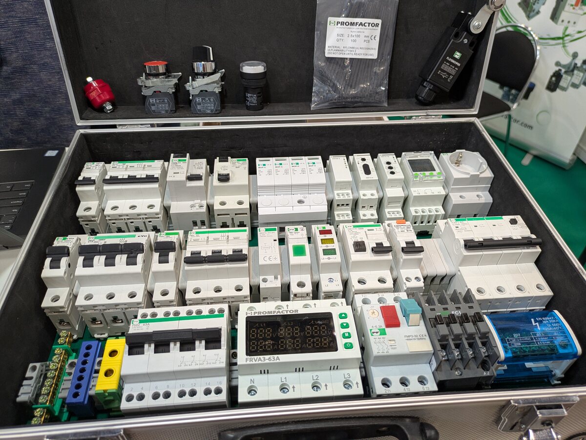
challenge. Designed to operate completely spark-free, they meet the ignition-free requirements for A2L and A3 refrigerants. These relays make continuous phase sequence and phase loss monitoring, ensuring that compressors are always protected from the main grid failures [/c] ### Bourns – monolithische
Speichermarkt einsteigt. Was es sonst Neues an Bauteilen gibt, verraten wir – wie immer – hier. ### QPD2560L – HEMT-Verstärker mit 300 W für 1.0 – 1.5 GHz, Im Hause Qorvo lanciert man einen HEMT, der ob seiner Leistungsdaten besonders für die Bedürfnisse vom im L-Band arbeitenden Radaranwendungen optimiert
SE873K5-D and SE869eK5-DRK provide a scalable path for device manufacturers to: • Adopt dual-band L1 + L5 GNSS • Leverage advanced correction technologies • Implement resilient positioning architectures without redesigning hardware [/c] ### Stackpole - Dünnfilmwiderstände
0 0 100 5 _ 5 1 R R 3 0 B C n C . 0 / 0 1 0 0 0 5 P 4 V 4 / C 0 D D 5 7 2 U C 4 MF40520 2 R5409 5P 200MM B&C L A 100 +3.3M 1 3.29V T ST542 I C5443 5 DGND 2 0.00V G 4 D5408 Page 76 L6 s545 5 1SS355VM ACPWR_DET 3 3.26V I 8 D IC542 PRY D to DIGITAL_CB64 C5408 4 2.45V TEST m no_use 5 3.24V o r JUCVPS ZP42540
rating. The gaskets are available in various standard profile shapes: square, as well as D, C, P, L, M, and blade profiles. [/c] ### SamTec Generate - Steckverbinder für Seitenkontakte Je weniger Steckverbinder ein System benötigt, desto kostengünstiger ist es. SamTec lanciert nun eine Steckerfamilie
ratings up to: 0.5 W in 0603 1 W in 0805 2 W in 1206 6 W in 2512 RMCA – AEC Q200-zertifiziert mit höherer Leistung The RMCA product line now includes two enhanced high-power options: the “-HP” and the even higher-rated “-UP” versions. These variants elevate the power handling
Characteristics and ordering codes Mate- A value Ordering code Magnetic characteristics Approx. L i rial (approx.) l/A e A e Ve weight nH mm –1 mm mm 2 mm 3 g N87 1390 25% 2200 B64290L0652X087 2.00 42.00 21.04 884 4.4 N30 2710 25% 4300 B64290L0652X830 T65 3250 30% 5200 B64290L0652X065 T35 3770 25% 6000 B64290L0652X035 T37 4080 25% 6500 B64290L0652X037 T38 6280 30% 10000 B64290L0652X038 N87: P V200 mT, 100 kHz, 100 °C) < 0.55 W/core 1) On request. Please read Cautions and warnings and Important notes at the
( L S L -15 1 25 E U T H R -20 I C -25 20 T O 0.1 dB Compression Point I -30 15 W 0 1 2 3 4 5 6 7 8 0 1 2 3 4 5 6 7 8 S FREQUENCY (GHz) S FREQUENCY (GHz) Input Third Order Intercept Point B 60 55 ) d50 O
different temperatures Figure 5. V versus ID for different temperatures CE F (VDD = 15 V) 800 250 200 600 TJ= 100C 150 TJ= 100C ]400 ] μ TJ= 25C μ n f 100 o o TJ= 25C E200 E 50 0 0 0 2 4 6 8 10 12 14 16 18 20 0 2 4 6 8 10 12 14 16 18 20 Ic [A] Ic [A] Figure 7. EOFF versus ID for different temperatures
Gewerbetreibende 1-48 Lagen Leiterplatten und SMD-Schablonen, ab 1AT Express, seit 30 Jahren Standard 2L: 4AT Produktionszeit, 4L: 5AT Produktionszeit, 6L & 8L: 6AT Produktionszeit Standard: 0.1mm Leiter, 0.2mm Bohren Preiswerte Spar-Option ab 8AT Inklusive: Kompletter Design-Rule-Check, Tooling, Lötstopp
Standort: Würzburg (Bayern), Deutschland GBS Elektronik GmbH. Homepage: SH Elektronik GmbH. Homepage: L^2 Electron Design. Homepage: Mail: mailto:kontakt@l2electrondesign.de Fokus liegt auf preiswertem & schnellem Rapid Prototyping Bestückung ab einer Platine und kleiner Varianz Begleitung vom Prototyp

 Bild
Bild
 Bild
Bild
 Bild
Bild
 Bild
Bild
 Bild
Bild
 Bild
Bild
 Bild
Bild
 Bild
Bild
 Bild
Bild