-
Bild
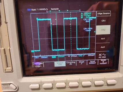
Abfotografierter Bildschirm eines Oszilloskops mit Rechtecksignal
Tek Run: 1.00MS/s Sample 500mV 555µs -2mV Ch1 Max 8mV Ch1 Min -8mV Edge Source Ch1 Ch2 Ax1 Ax2 AC AC Line Ch1 100mV Ch2 100mV M 250µs Ch2 280mV Type <Edge> Source Ch2 Coupling DC Slope / Level 280mV Mode & Holdoff
in „[V] Tektronix TDS 524A Oszilloskop 500 MHz“ · Markt · · Fotos
-
Bild
Technische Spezifikationen eines SDS1000X-E Oszilloskops
Rate Memory Depth Peak Detect Average Eres Waveform interpolation Input Channels Coupling Impedance Max. Input voltage CH to CH Isolation Probe attenuation Vertical System Bandwidth Vertical Resolution Vertical Scale (Probe 1X) Offset Range (Probe 1X) Bandwidth Limit Bandwidth Flatness Low Frequency Response (AC -3 dB) Noise SFDR including harmonics DC Gain Accuracy Offset Accuracy Risetime Overshoot (500 ps Pulse)
in „Ringing "zweiter Peak" im Buck Converter“ · Analoge Elektronik und Schaltungstechnik · · Screenshots
-
Bild
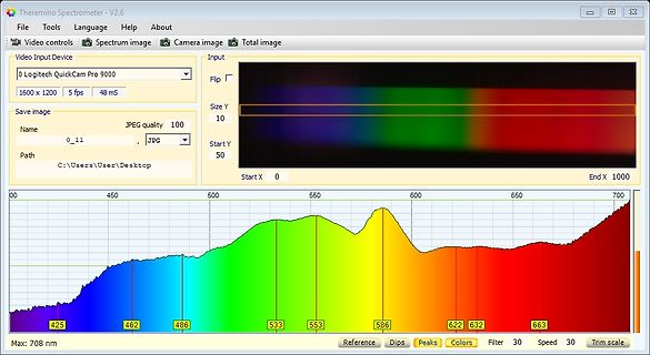
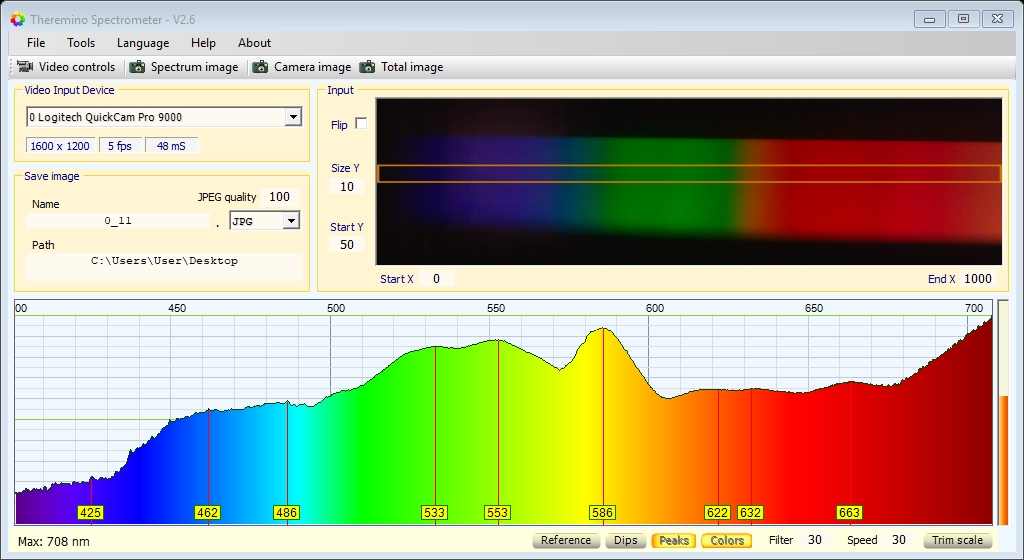
Softwareoberfläche eines Spektrometers mit Wellenlängenmessung
11 JPEG quality 100 Path C:\Users\User\Desktop Input Flip Size Y 10 50 Start X 0 End X 1000 00 450 500 600 650 700 425 462 486 533 553 586 622 632 663 Max: 708 nm Reference Dips Peaks Colors Filter 30 Speed Trim scale
in „Physikprojekte“ · Offtopic · · Screenshots
-
Bild
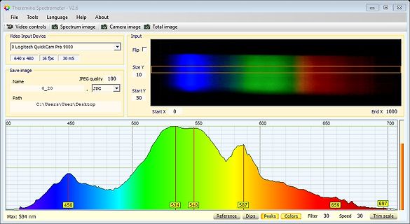
Softwareoberfläche eines Spektrometers mit Spektralkurve
Name 0_20 JPG Path C:\Users\User\Desktop Input Flip Size Y 10 Start Y 50 Start X 0 End X 1000 00 450 500 550 600 650 700 450 534 548 587 659 697 Max: 534 nm Reference Dips Peaks Colors Filter 30 Speed Trim scale
in „Physikprojekte“ · Offtopic · · Screenshots
-
Bild
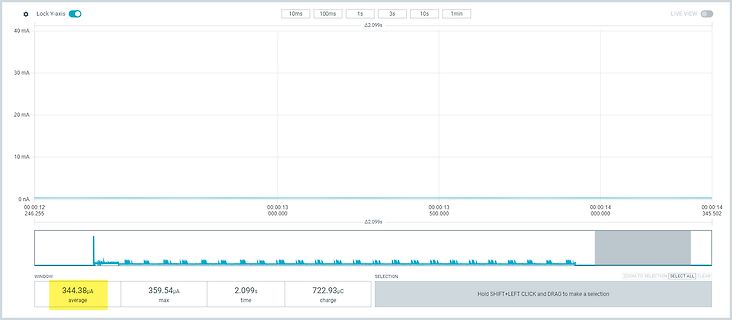
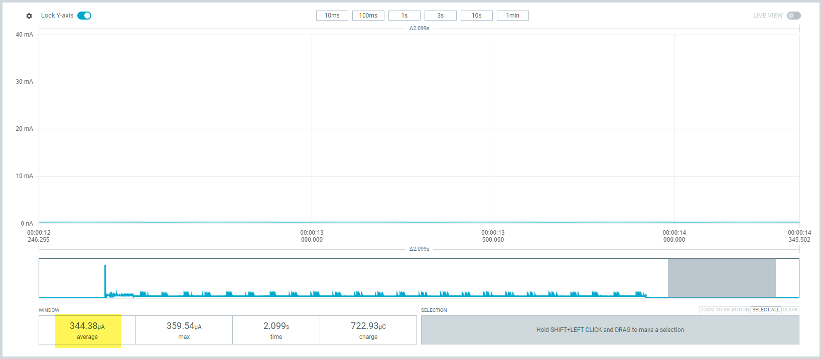
Screenshot einer Strommessung mit Zeitverlauf
100ms 1s 3s 10s 1min LIVE VIEW 40 mA 30 mA 20 mA 10 mA 0 nA 00:00:12 246.255 00:00:13 000.000 00:00:13 500.000 00:00:14 000.000 00:00:14 345.502 Δ2.099s WINDOW 344.38µA average 359.54µA max 2.099s time 722.93µC charge SELECTION ZOOM TO SELECTION SELECT ALL
in „ESP32-H2 will nicht schlafen“ · Mikrocontroller und Digitale Elektronik · · Oszi-Bilder
-
Bild
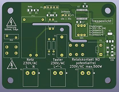
PCB-Layout einer Treppenlicht-Steuerung
Relais EIN F1 Netz 230V/AC L N X1 X2 Taster 230V/AC L - L X3 Relaiskontakt NO potentialfrei 230V/AC max.500W
in „230v Kann man das so machen?“ · Platinen · · Layouts
-
Bild
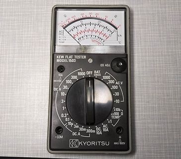
Kew Flat Tester Kyoritsu Model 1503 Analogmultimeter
Ω, 50, 30, 20, 10, 5, 0, 2k, 500, 200, 100, 10, 2, 1, AC, DC, V.A, AC 10V, AC 10A, TEMP, 40, 30, 20, 10, 0, KEW FLAT TESTER MODEL 1503, Ω ADJ., 1000, OFF, BAT. CHECK, 300, AC.V, 10A, 300, 100, 10A, 100, 30, 30, 10, DC.V, 1, x10k, 3, x100 Ω, 0.3, 10, TEMP, 0.1, x1, 3m, 30m, 300m, DC, 10A, -COM, DC.A, KYORITSU, MAX 1000V
in „[V] Kyoritsu 1503 Analogmultimeter“ · Markt · · Fotos
-
Datei
eventcb_ctrl6.ino
TimerA_adcpin, TimerA_event); // TimerA stellt Zeit über eingelesenen ADC-Wert ein TIMERSOFT TimerB(500, TimerB_event); // TimerB erzeugt Intervall mit 500 ms TIMERSOFT AppTimer(100, AppTimer_event); // Timerintervall, mit der Funktionen aufgerufen werden, // die I/O Aktionen auf dem UART vornehmen, hier
in „Schulnotenbewertung eines Arduino-Programms“ · Mikrocontroller und Digitale Elektronik ·
-
Bild
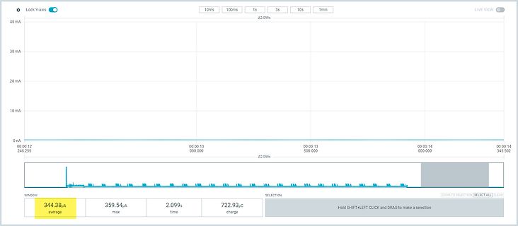
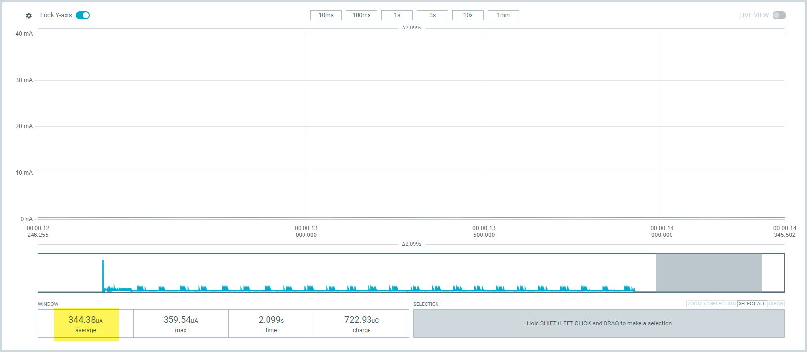
Screenshot einer Strommessung mit Zeitverlauf
100ms 1s 3s 10s 1min LIVE VIEW 40 mA 30 mA 20 mA 10 mA 0 nA 00:00:12 246.255 00:00:13 000.000 00:00:13 500.000 00:00:14 000.000 00:00:14 345.502 Δ2.099s WINDOW SELECTION ZOOM TO SELECTION SELECT ALL 344.38µA average 359.54µA max 2.099s time 722.93µC charge Hold SHIFT+LEFT CLICK and DRAG to make a selection
in „ESP32-H2 will nicht schlafen“ · Mikrocontroller und Digitale Elektronik · · Oszi-Bilder
-
Bild
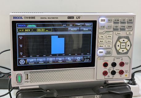
Rigol DM858E Digitalmultimeter
Auto - Meas Help Range - Auto Hold Single Local CAT I (mV) 200Vpk CAT II (A) LO 3.15A/250V I Fuse 500Vpk MAX Input LO HI 3A RMS LO HI
in „Amper 2026 – auf neuen Wegen herunterskillen“ · Mikrocontroller und Digitale Elektronik · · Fotos
-
Bild
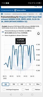
Preisentwicklung für Kingston FURY Beast RGB RAM
28.12.2025 (letzter Preis: € 679,90) Keine Angebote in diesem Zeitraum € 679,90 14.12.2025 € 700 € 600 € 500 € 400 € 300 € 200 28.11. 2025 05.12. 12.12. 19.12. 26.12. 1M 3M 6M 1J Max Wichtige Ereignisse Trend Median
in „Lustige DDR5 RAM Preise“ · Offtopic · · Screenshots
-
Bild
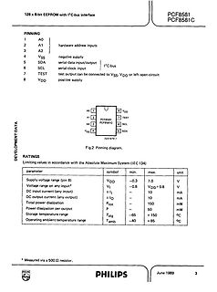
Datenblattseite eines PCF8581 EEPROM Chips
1 A0 2 A1 3 A2 4 VSS 5 SDA 6 SCL 7 TEST 8 VDD Fig.2 Pinning diagram. RATINGS parameter symbol min. max. unit Supply voltage range (pin 8) VDD -0.3 7.0 V Voltage range on any input* VI -0.8 VDD+ 0.8 V DC current (any input) ± 10 mA DC output current (any output) ±0 10 mA Total power dissipation Ptot 150
in „IC-Idenifikation für Garagentor Zahlenschloß“ · Mikrocontroller und Digitale Elektronik · · Screenshots
-
Bild
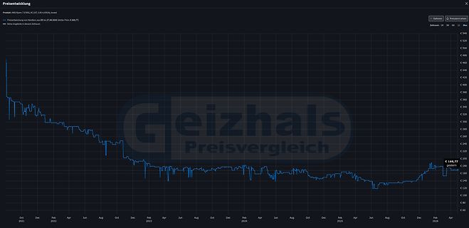
Preisentwicklung eines AMD Ryzen 7 5700G
Preis: € 169,77) Keine Angebote in diesem Zeitraum Optionen Preisalarm setzen Zeitraum: 1W 3M 6M 1J Max € 540 € 520 € 500 € 480 € 460 € 440 € 420 € 400 € 380 € 360 € 340 € 320 € 300 € 280 € 260 € 240 € 220 € 200 € 180 € 169,77 gesamten € 160 € 140 € 120 € 100 € 80 € 60 Oct 2021 Dec Feb Apr Jun Aug Dec
in „AMD Ryzen, welche Geschwindigkeitsunterschiede“ · PC Hard- und Software · · Screenshots
-
PDF
ErklearungDriverSimulation.pdf
TABLE { V(0, 58) } ((-1,-1u)(0,0)(25,0.01)(40,0)) * Source Output E67 67 0 TABLE { V(69, 0) } ( (-500M,-500M)(0,0)(1,2.00) ) G63 0 63 POLY(1) 3 4 60.7 -5.97 194M R63 0 63 1 TC 3.75M 321n E61 61 65 VALUE {V(67,0)*V(63,0)} V63 65 3 100U G61 61 60 TABLE { V(61, 60) } (-20.0M,-50.0)(-15.0M,-25.0)(-10.0M,-5.00)(0,0)(10,1N)) * Sink Output E68 68 0 TABLE { V(69, 0) } ( (-1,-2.00)(0,0)(500M,500M) ) G64 0 64 POLY(1) 3 4 16.1 -1.19 38.8M R64 0 64 1 TC 5.19M 21.8U E62 62 66 VALUE {V(68,0)*V(64,0)} V64 66 4 100U G62 60 62 TABLE { V(60, 62) } (-20.0M,-50.0)(-15.0M,-25.0)(-10.0M,-5.00)(0,0)
in „Spice Simulation von Treiber TC4229“ · Analoge Elektronik und Schaltungstechnik ·
-
PDF
TCXO.pdf
雅晶鑫電子 P/N:TAXM32M4ZFBCCT2T ● ELECTRICAL PARAMETERS 谐振器产品技术指标 Min Max Units 1.Holder Type(型号规格) SEAM 2.0*1.6 2.Mode of Oscillation(振动模式) Fundamental 3.Frequency(标称频率) 32.000000 MH Z 4.Load Capacitance (CL)(负载电容) 12 pF 5.Shunt Capacitance (Co)(静态电容) 0 5 pF 6.Equivalent
in „868MHz Impedanzmatching - Fragen zum Matching-vorgehen“ · HF, Funk und Felder ·
-
Bild
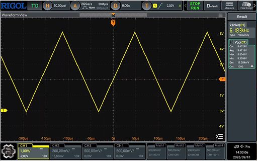
Oszilloskop-Screenshot eines Dreiecksignals
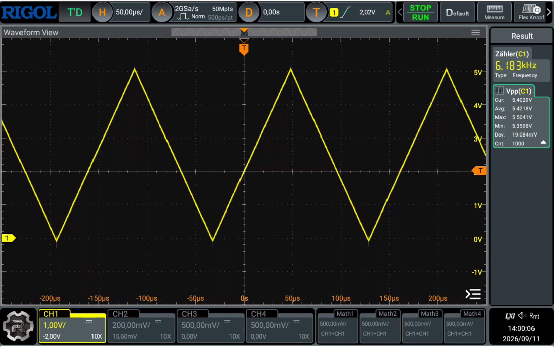
STOP RUN Default Measure Flex Knob Waveform View Zähler(C1) 6.183kHz Type: Frequency Cur: 5.4029V Max: 5.5041V Avg: 5.4218V Min: 5.3598V Dev: 19.084mV Cnt: 10 4V 1V 0V -1V T CH1 1,0V/ -2,0V 10X CH2 20mV/ 15,60mV 10X CH3 50mV/ 0,0V 10X CH4 50mV/ 0,0V 10X Math3 50mV/ Math4 500mV/ CH1+CH1 CH1+CH1 CH1+CH1
in „[V] Wavetek Model 180 Sweep Funktionsgenerator bis 2 MHz“ · Markt · · Oszi-Bilder
-
Bild
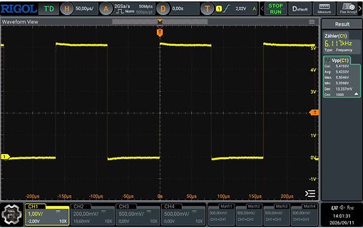
Oszilloskop-Screenshot eines Rechtecksignals
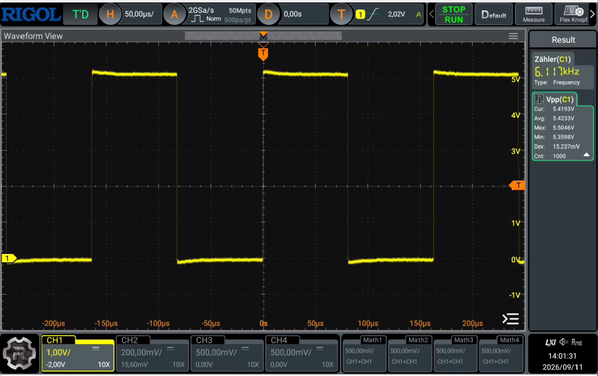
2,02V STOP RUN Default Measure Flex Knob Waveform View T Zähler(C1) 6,17kHz 5V Vpp(C1) Cur: 5,423V Max: 5,504V Avg: 5,423V Min: 5,359V Dev: 15,237mV Cnt: 100 4V 1V 0V -1V CH1 1,0V/ -2,0V 10X CH2 20,0mV/ 10X CH3 50,0mV/ 10X CH4 500,0mV/ 10X Math1 CH1+CH1 Math2 CH1+CH1 Math3 50,0mV/ Math4 50,0mV/ 14:01
in „[V] Wavetek Model 180 Sweep Funktionsgenerator bis 2 MHz“ · Markt · · Oszi-Bilder
-
PDF
MS9585b_EFD20_ub.DB.pdf
34 : 2424 in SMD-Bauform - Elektrische Trennung Pri – Sec : 1,25kV Prüfspannung - Surge-Test W3 mit 500V/3 Pulse: 122mVs +20%/-40% - Imprägniert mit Voltatex 4001 - RoHS konform Elektrische Übersetzung: 34 : 2424 Daten: Max. Umgebungstemperatur: +70°C Isolierstoffklasse: B ( 130°C ) Spannungsfestigkeit
in „Trafo Vermessen Sättigungsstrom“ · Analoge Elektronik und Schaltungstechnik ·
-
Bild
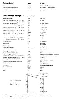
Datenblatt mit technischen Spezifikationen eines Netzteils
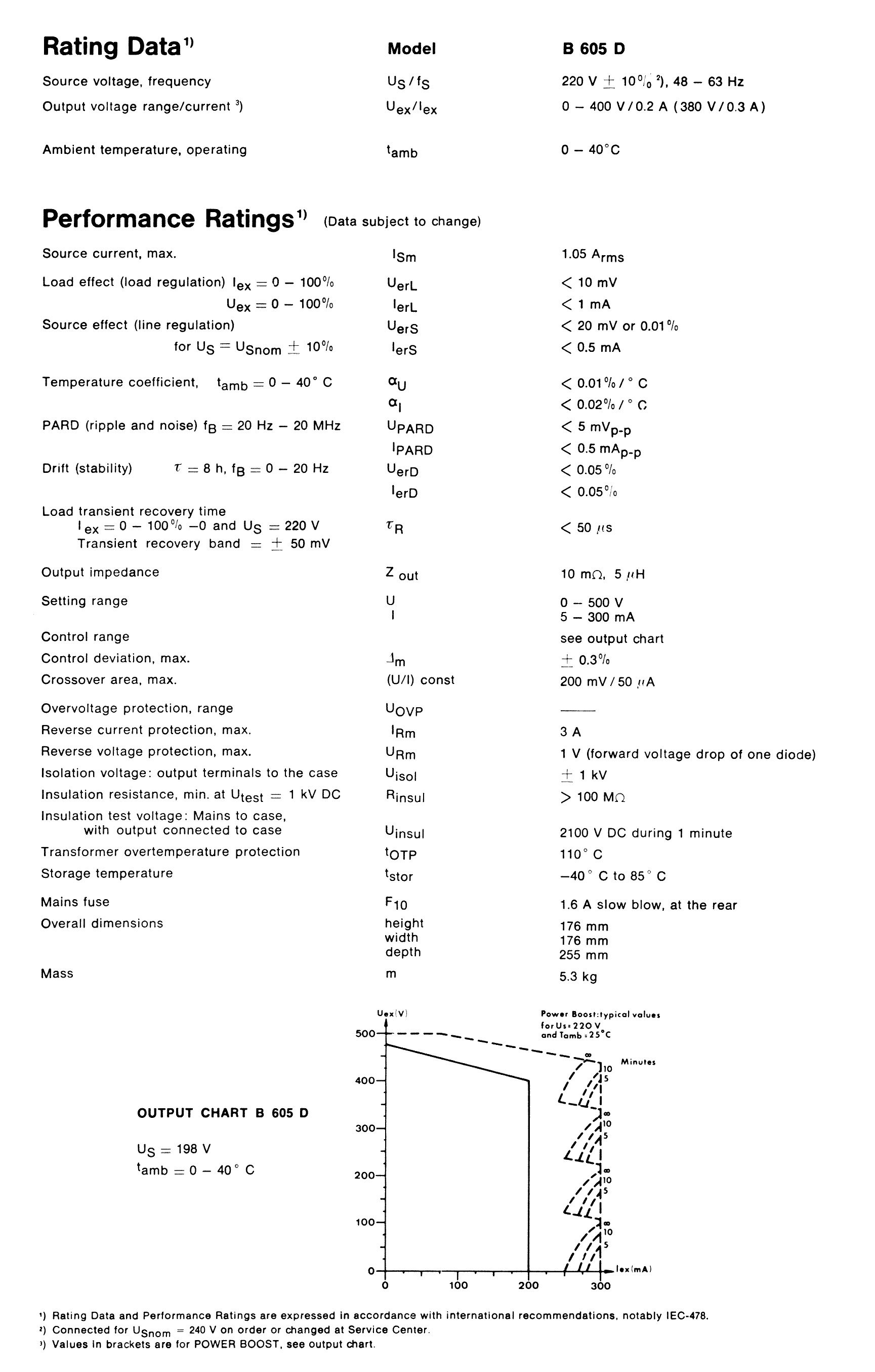
V/0.3 A) Ambient temperature, operating tamb 0 - 40°C Performance Ratings Uex/Iex Source current, max. Ism 1.05 Arms Load effect (load regulation) IerL < 1 mA PARD (ripple and noise) fB = 20 Hz - 20 MHz < 5 mVp-p Drift (stability) t = 8h, fB = 20 Hz < 0.05% Load transient recovery time t = 8h, US = 220 V < 50 µs Output impedance Z out 10 mΩ, 5 µH Setting range U 0 - 500 V, I 0 - 300 mA Isolation voltage UisoL 1 V (forward voltage drop of one diode) Transformer overtemperature protection tOTP 110°C Mass m 5.3 kg
in „[S] Suche Schaltbild zu Netzteil OLTRONIX B605D (400V / 200 mA)“ · Markt · · Screenshots
-
Bild
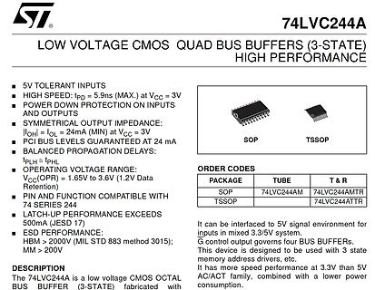
Datenblatt des 74LVC244A CMOS Quad Bus Buffers
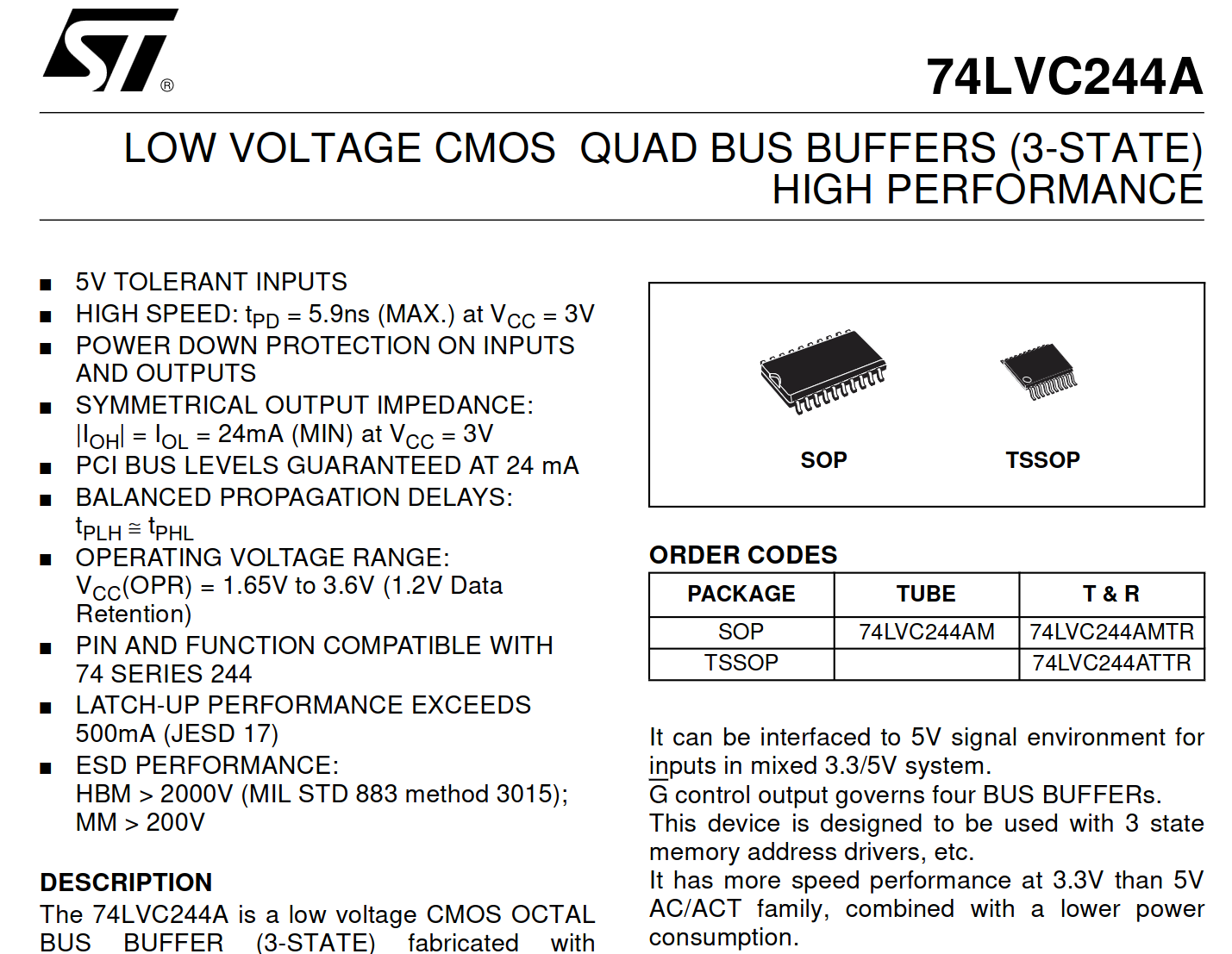
VOLTAGE CMOS QUAD BUS BUFFERS (3-STATE) HIGH PERFORMANCE 5V TOLERANT INPUTS HIGH SPEED: tPD = 5.9ns (MAX.) at VCC = 3V POWER DOWN PROTECTION ON INPUTS AND OUTPUTS SYMMETRICAL OUTPUT IMPEDANCE: |OHL = IOL = 24mA (MIN) at VCC = 3V PCI BUS LEVELS GUARANTEED AT 24 mA BALANCED PROPAGATION DELAYS: tPLH = tPHL
in „ISE14.x und chinesisches Platform Cable USB geht nicht“ · FPGA, VHDL & Co. · · Screenshots
-
Bild
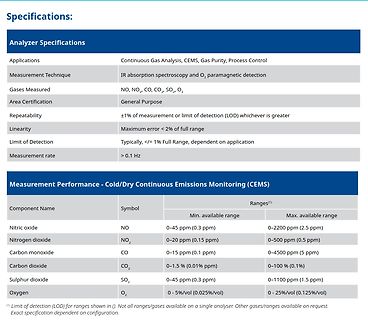
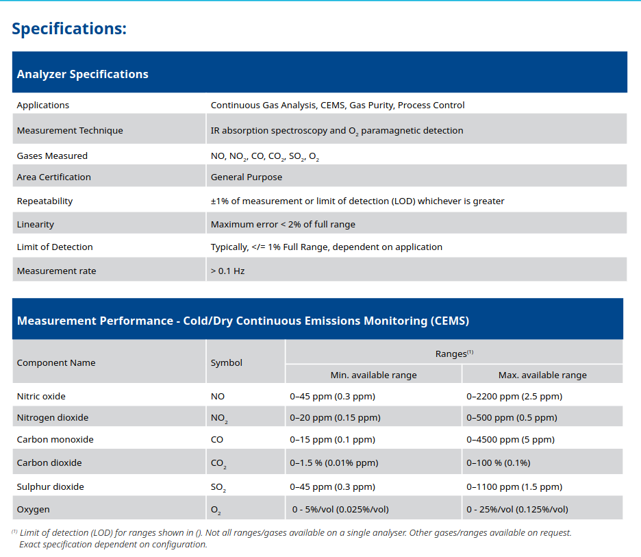
Tabelle mit Analysator-Spezifikationen und Messbereichen
- Cold/Dry Continuous Emissions Monitoring (CEMS) Component Name | Symbol | Min. available range | Max. available range Nitric oxide | NO | 0-45 ppm (0.3 ppm) | 0-2200 ppm (2.5 ppm) Nitrogen dioxide | NO2 | 0-20 ppm (0.15 ppm) | 0-500 ppm (0.5 ppm) Carbon monoxide | CO | 0-15 ppm (0.1 ppm) | 0-4500 ppm
in „Neue Bauteile: vom Radar bis zum Widerstand“ · Mikrocontroller und Digitale Elektronik · · Screenshots
-
PDF
WS2812B__Ver._No._V5__EN_19112715001349.pdf
Electrical Characterist(csTA=25℃, V DDV, V =0SS unless otherwise specified) Parameter Symbol Min Tpy Max Unit Conditions Input current I —— —— ±1 µA V IV DD SS High Voltage Input VIH 2.7V —— VDD+0.7V V DINSET Low Voltage Input VIL -0.3V —— 0.7V V DINSET 2/8 http://www.world-semi.com WS2812B Ver. No.: V5
in „Adressierbare RGB LEDs 3.3V gesucht“ · Mikrocontroller und Digitale Elektronik ·
-
PDF
Merkblatt_-_baus._Steuerungssysteme_fuer_WAREMA_Sonnenschutzbehaenge.pdf
empfehlen wir Ihnen die die gleiche Richtung Umschaltpausen von Kontaktaufnahme mit unserem Kundencenter >500 ms ein. Eine direkte Umschaltung ohne Steuerungssysteme. Pausenzeit ist nicht zulässig. ■ Verriegelung: Schaltkontakte für Hoch und Tief müssen ge- geneinander verriegelt sein. Bitte verhindern Sie,
in „Ausschaltverzögerung für ein Relais“ · Analoge Elektronik und Schaltungstechnik ·
-
PDF
SA612A.PDF
regulator. It is intended for low cost, low power communication systems with signal frequencies to 500MHz and local oscillator frequencies as high as 200MHz. The INPUT A 1 8 VCC INPUT B 2 7 OSCILLATOR mixer is a “Gilbert cell” multiplier configuration which provides gain of 14dB or more at 45MHz. GND
in „Langwellen Minimal SDR mit sa612 und SI5351“ · HF, Funk und Felder ·
-
PDF
Magazin_Bauteile.pdf
0,00 2 10 4 LEER 0,00 2 10 5 LEER 0,00 2 11 1 1 Platinenhalter 2 Stk. für Baugruppenträger RS PRO RS 500-847 17,370 17,37 1 Kunstoff-Schraubenhalter für Frontplatten für Baugruppenträger Bopla Bopla 8608 0510 ISH/M 19 1 Metall-Schraubenhalter für Frontplatten für Baugruppenträger 2 11 2 45 Kabel 12cm für
-
PDF
ME2108_Series.pdf
0VÿI▯ =10mAÿT ▯ =25!▯ 0▯ IN SS OUT opt ME2108Axx/Cxx Fosc=180kHz SYMBOL PARAMETER CONDITIONS MIN TYP MAX UNITS V OUT Output Voltage Vout*0.975 Vout Vout*1.025 V Oscillation IOUT=1mAÿ▯ Vstart Start-up Voltage V ÿ▯ 0→2V 0.8 0.9 V IN Oscillation Hold IOUT=1mAÿ▯ Vhold Voltage V IN 2→0V 0.45 V Supply Current
in „Alle Jahre wieder: Fundstück in Weihnachtsbeleuchtung“ · Analoge Elektronik und Schaltungstechnik ·
-
Datei
MSP3400_ATMEGA32_ADC_2.ino
uint8_t getBrightnessFromADC() { int adc = analogRead(A0); const int ADC_MIN = 0x0A0; const int ADC_MAX = 0x15E; if (adc < ADC_MIN) adc = ADC_MIN; if (adc > ADC_MAX) adc = ADC_MAX; return map(adc, ADC_MIN, ADC_MAX, 2, 14); } void showSymbol(uint16_t sym) { sendFrame(0, sym, 1); } void showSymbolDimmed
in „Zeigt her eure Kunstwerke (ab 2023)“ · Projekte & Code ·
-
Datei
MSP3400_ATMEGA32_ADC_2.ino
uint8_t getBrightnessFromADC() { int adc = analogRead(A0); const int ADC_MIN = 0x0A0; const int ADC_MAX = 0x15E; if (adc < ADC_MIN) adc = ADC_MIN; if (adc > ADC_MAX) adc = ADC_MAX; return map(adc, ADC_MIN, ADC_MAX, 2, 14); } void showSymbol(uint16_t sym) { sendFrame(0, sym, 1); } void showSymbolDimmed
in „AUDIOCONTROLLER MSP3400C einfach mit ATMEGA32 ansteuern“ · Projekte & Code ·
-
PDF
SFJ_series_Datasheet.pdf
voltage can be cut off by fuse. It doesn't represent the operational voltage of the heater. Reflow Temp.(MAX) 260 °C *Notice:The specification may be subject to change without prior notice in the future. 3 SFJ-xx22U Series Specification ●Products Lineup Applicable Cells in series 1 cell 2 cells 3 cells 4 cells
in „IC-Identifikation: Q5A + KK9“ · Analoge Elektronik und Schaltungstechnik ·
-
PDF
panasonic-126584-BK-3MCCF.pdf
Japan Capacity 1) Minimum 1900mAh 14.35 mm Nominal Voltage 1.2V Charging Current x Time Fast Charge 2) Max.1900mA Charge Fast Charge 2) 0°C - 40°C Condition Discharge Condition -20°C - 50°C 50.4 mm Ambient Temp. Less than Storage 90days -20°C - 40°C Condition Less than -20°C - 30°C 1year Internal Impedance
in „Batteriefach zum Einbau in Gehäuse mit Deckel“ · Mechanik, Gehäuse, Werkzeug ·
-
PDF
moxa-awk-1137c-series-datasheet.pdf
2.412 to 2.462 GHz (11 channels) 5.180 to 5.240 GHz (4 channels) 2 5.260 to 5.320 GHz (4 channels) 5.500 to 5.700 GHz (11 channels)2 5.745 to 5.825 GHz (5 channels) 1. 20-MHz RF channels, WPA2-PSK security, and default Turbo Roaming parameters. The clients are configured with 3-channel roaming at 100 Kbps
in „[V] Diverse Moxa Industrie Switche und Access Points“ · Markt ·
-
PDF
2S-0830-V1-2.pdf
Cut load Detection condition Exterior short circuit Short protection Short Detection delay time 150-500us Release condition Cut short circuit Interior resistance R Main loop electrify resistance VC=3.8V;R ≤DSmΩ DS Current consumption IDD Current consume in normal operation 3μA Type 15μA Max Specification
in „akkupack litium Ionen 2S2P 3AH für Handfunkgerät Icom IC2E“ · Analoge Elektronik und Schaltungstechnik ·
-
PDF
statron3257.pdf
2) Betriebstemp. 0 - 20- 35°C Ausgangsbuchsen Apparatekl. schraub-/steckbar 4mm Sicherheitsbuchsen max. relative Luftfeuchte 85% bei 35°C AC Eingangsspannung 230 V +6 / -7% 48-62Hz AC Prüfspannungen Eing.-Masse1,5kV; Prim.-Sek.1,5kV; Ausg.-Masse 500VAusgang-Masse 1000V Schutzklasse und -grad I / IP30
in „[V] Statron 3257.1 36V/40A 1440W lineares Netzgerät NEU“ · Markt ·
-
PDF
L9110-Motor-Driver-Datasheet.pdf
chip L9110 Electrical characteristics: Logical relationship: SymbolParameters Range Units Min TypicalMax IA IB OA OB VCC Supply Voltage 2.5 6 12 V Quiescent Current H L H L Idd - 0 2 uA L H L H Iin Operating current200 350 500 uA L L L L IC Continuous 750 800 850 mA Current peak H H L L IMax - 1500 2000
in „Motorcontroller (H-Brücke) gesucht, der schon mit einer LiPo Zelle funktioniert?“ · Analoge Elektronik und Schaltungstechnik ·
-
PDF
CY7C65642-28LTXC__4x_HUB__Infineon.pdf
be1 to 4.Default value is 4. Byte8: Maximum Power ThisvalueisreportedintheConfigurationDescriptor:bMax-Powerfieldandisthecurrentin2mAincrements thatisrequired from the upstream hubs.Theallowedrangeis 00h (0 mA)to FAh(500mA).Default value is 32h (100 mA) Byte9–15: Reserved Set to FFh (except 11 which
in „USB-Hub funktioniert nicht.“ · Mikrocontroller und Digitale Elektronik ·
-
PDF
moxa-eds-405a-series-datasheet.pdf
256 MAC Table Size EDS-405A, EDS-405A-EIP/MM-SC/MM-ST/PN/SS-SC models: 2 K EDS-405A-PTP models: 8 K Max. No. of VLANs 64 Packet Buffer Size 1 Mbits Priority Queues 4 VLAN ID Range VID 1 to 4094 Serial Interface Console Port RS-232 (TxD, RxD, GND), 10-pin RJ45 (115200, n, 8, 1) DIP Switch Configuration
in „[V] Diverse Moxa Industrie Switche und Access Points“ · Markt ·
-
PDF
ESP32_Prototyp_1.pdf
1 2 3 4 5 6 10K = 100mA 5.0K = 200mA U1 2.0K = 500mA MCP73831/2 1.0K = 1000mA Akku Pinheader PWR_FLAG LIPO Charger PWR_FLAG VBAT þÿfürAkku VBUS 5V 4 VDD VBAT 3 R3 1 1 LED1 5 2 D+ F R1 PROG 10K\ F 2 A D- 1 0 470 1 STAT VSS 2 2 0 A C ÿ RED C ÿ CC1 þ þ
-
PDF
infineon-ug-202311-pl52-2312-121012-solid-state-circuit-breaker-reference-design-user-guide-usermanual-en.pdf
Solid-state circuitbreakerreferencedesignuserguide SSCBdevices ata glance Table3 Parameter Parameter Min Typ Max Unit Absolutemaximumchannelsupplyrange 90 – 260 VAC 120 – 375 VDC Operatingchannelsupplyrange 100 – 240 VAC 330 – 370 VDC NominalcurrentatTa=25°C – 16 – A StaticoverdrivefactoratTa=25°C – – 1.13 – I
in „Leitungsschutzschalter 24VAC“ · Analoge Elektronik und Schaltungstechnik ·
-
PDF
STK625-728.pdf
C Parameter Symbol Conditions Ratings unit Supply voltage VCC + - U - (V -, W -) terminal, surge < 500V *1 450 V Collector-emitter voltage VCE + - U (V, W) terminal or U (V, W) - U - (V -, W -) terminal 600 V Output current IO +, U -, V -, W -, U, V, W terminal current ±10 A Output peak current Iop +
in „KI gefuehrte Fehlersuche an Waschmaschine Panasonic NA-168VG3“ · Analoge Elektronik und Schaltungstechnik ·
-
PDF
Datenblatt-KFD.pdf
Dimensions (18 ±1 mm) Dimensions P 8 mm oder / or / ou 15 mm RM 25 mm 30 mm C 94 ±2 mm 101 ±2 mm f max. 109 mm max. 116 mm Trägerkörper Glasfaserkordel Carrier Fiber glass core Support Fibre de verre Widerstandswertbereich Resistance range CuNi 10 R051 – R11 R10 – R22 R18 – R39 Plage de valeurs CuNi
in „[VS] verschenke ca. 200 Stück Widerstände 100 Ohm 10(?) Watt“ · Markt ·
-
PDF
W5500_ds_v110e.pdf
Timing TRC RSTn TPL PLOCK (Internal) Figure 22. Reset Timing Symbol Description Min Max TRC Reset Cycle Time 500 us - T PL RSTn to internal PLOCK (PLL Lock) - 1 ms 5.5.2 Wake up Time Voltage Regulator Wake up Time: 10us 5.5.3 Crystal Characteristics Parameter Range Frequency 25 MHz Frequency
in „Schaltung W5500“ · Mikrocontroller und Digitale Elektronik ·
-
PDF
extended_serial_library.pdf
ab der ein Text vertikal ausgegeben wird col : das Farbattribut, mit dem der Text ausgegeben wird max : die maximale Anzahl an Zeichen, die ausgegeben wird. Erreicht die Zeichenausgabe diesen maximalen Wert, wird die Ausgabefunktion auch dann beendet, wenn das Stringende noch nicht erreicht war *cptr
in „Arduino und struct gefallen sich nicht !“ · Mikrocontroller und Digitale Elektronik ·
-
PDF
FD6287T_fortiorEnglish.pdf
IQBS VIN=0V or 5V -- 180 270 ÿA -- VBS dynamic current IPBSfHIN1,2,3=20kHz 180 270 ÿA IQCC -- 330 500 uA VCC quiescent current VIN = 0V or 5V VCC dynamic current IPCC fLIN1,2,3=20kHz LIN* High-level -- 330 500 uA -- input bias current ILIN+ VLIN=0V LIN* Low-level input bias current ILIN- VLIN=5V HIN
in „hc-160a s2 Datenblatt?“ · Mikrocontroller und Digitale Elektronik ·
-
PDF
BA3217_1984.pdf
Gleichspannungsregler stark beschädigt werden. Technische Daten Netzspannung 220 V ±10 %50 Hz ±3 % max. 450 W Ausgangsspannung 0,05 ... 30 V (massefrei, stufenlosmit 10-Gang- Potentiometer einstellbar) Ausgangsstrom (stufenlos 0,05 ... 10 A einstellbar) Stabilisierung Netzspannungsänderungen ±10 % Änderung·derAusgangsgröße Konstantspannungsbetrieb (CV) 0,01 % +10 µV Konstantstrombetrieb (CC) 0,05 % +500 µA Laständerungen 100 % Konstantspannungsbetrieb (CV) 5mV Konstantstrombetrieb (CC) 2mV Regelzeit (bei sprunghafter Laständerung um 100%) 100µs
in „Das Statron 3217/16 Projekt“ · Analoge Elektronik und Schaltungstechnik ·
-
Datei
sanduhr_1.html
; padding: 18px 16px 30px; box-sizing: border-box; } h1 { margin: 0; font-size: 20px; font-weight: 500; letter-spacing: .22em; text-transform: uppercase; color: #c9a86a; } canvas { display: block; width: 100%; max-width: 430px; height: auto; touch-action: manipulation; } .hud { display: flex; gap: 28px
-
Datei
ESP8266_WiFI_UDP_Server_OLED.ino
pointer Adafruit_SSD1306 *display; // Buffer for incoming UDP messages char udp_buffer[WIFICLIENT_MAX_PACKET_SIZE+1]; volatile uint16_t seconds = 0; volatile uint16_t newmsg = 0; // flag to display new message volatile uint32_t led_on = 0; // LED on time uint8_t newMACAddress[] = {0x00, 0x90, 0xB7,
in „UDP-Netzwerke(l)n mit kleinen Mikrocontrollern und WizNet W5100/W5500“ · Mikrocontroller und Digitale Elektronik ·
-
PDF
53131a_53132a_bedienungsanleitung_deutsch_komprimiert.pdf
NAL 2) anlegen. 1-13 Inbettri bnahme D rchführen von M sungen ngen CHANNEL1 Al C Damae Lvl: V OsMAX.502 CHAWJEL2 <θ√ Z ≡C≥k rh Ö: Damags Lvi: 5Vrms MAX.502 M/ Freq & MΓ Ď / Ratio E R E G U E ⁄√L I Freq Chl U Freq & ZI Ratio F RFreq G U E N E Ch 2 I πππr ~ιπ π π π π ππ I LJ-LILIL Ju u d L iu L Ju Freq
in „[V] HP/Agilent 53131a/53132a Bedienungsanleitung deutsch“ · Markt ·
-
PDF
Components_alphabetic_order.pdf
10 reltol 0.001 relative tolerance for convergence abstol 0.1 µA absolute tolerance for convergence MaxIter 500 maximum number of iterations before error HICUM L0 HICUM level 0, version 1.32 Symbol: Default Name Value Description is 1e-16 (Modified) saturation current it_mod off Flag for using third order
-
PDF
PMT_handbook_v4E.pdf
five minutes or more at a light level producing an anode current of approximately 0.1 microamperes. 500 V SUPPLY V 5 6 7 8 9 (minutes) VOLTAGE 0 V ON LIGHT LEVEL OFF 5 6 7 8 9 (minutes) 0.1 µA ANODE I max. OUTPUT Ii I min. OR Ii I max. I min. 5 6 7 8 9 (minutes) WARM-UP PERIOD THBV4_0441EA Figure 4-41
in „Suche nach geeignetem OpAmp als Impedanzwandler“ · Analoge Elektronik und Schaltungstechnik ·
-
PDF
lnix-s-a0001298418-1.pdf
185°F) Relative Humidity Operating: 5% to 95% non-condensing Shock/Vibration Non-operational shock: 500 g's, Non-operational vibration: 20 g's Warranty 2-year limited warranty Included Software Windows based DeviceInstaller configuration software & Windows based Com Port Redirector Supported Windows OS
in „[V] 1Stück gebrauchtes XPORT-EDGE_Seriell- LAN Modul (12€)“ · Markt ·