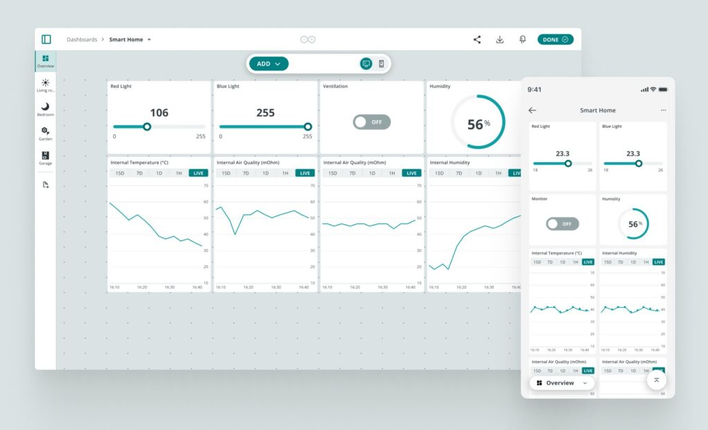
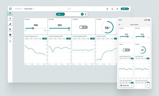
Dashboards Smart Home ADD Red Light 106 0 255 Blue Light 255 0 255 Ventilation OFF Humidity 56% 23.3 23.3 Internal Temperature (°C) Internal Air Quality (mOhm) Internal Humidity Internal Air Quality (mOhm) 15D 7D 1H LIVE 15D 7D 1H LIVE 15D 7D 1H LIVE 15D 7D 1H LIVE 9:41 Smart Home Red Light Blue Light 23.3 23.3 Monitor Humidity 56% OFF Internal Temperature (°C) Internal Humidity 15D 7D 1H LIVE 15D 7D 1H LIVE Internal Air Quality (mOhm) 15D 7D 1H LIVE Overview
/finitespace/BME280 The calibration algorithm is based on the Bosch documentation BST-BME280-DS001-23 Revision_1.23_012022 on page 25 To do single measurements, the code uses the "forced mode". The C code has been implemented on an ATmega328 with a 2 MHz crystal, using the Atmel-Studio 7 To interface
FROM wr WHERE DATE(timestamp) = DATE('now', '-1 days')));"[/code] liefert z.B.: [code]2026-02-22 17:23:26|153238|134788[/code] Nun möchte ich die Maxima der Leistung (Zeitpunkte uninteressant) auch eintragen, die Abfrage dafür [code]sqlite3 /dev/shm/log.db "SELECT MAX(p_pv_o), MAX(p_pv_w) FROM wr
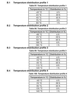
1
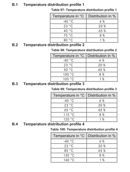
Table 97: Temperature distribution profile 1
Temperature in °C | Distribution in %
-40 °C | 6 %
23 °C | 20 %
40 °C | 65 %
75 °C | 8 %
80 °C | 1 %
B.2 Temperature distribution profile 2
Table 98: Temperature distribution profile 2
-40 °C | 6 %
23 °C | 20 %
50 °C | 65 %
100 °C | 8 %
105 °C | 1 %
B.3 Temperature distribution profile 3
Table 99: Temperature distribution profile 3
-40 °C | 6 %
23 °C | 20 %
65 °C | 65 %
115 °C | 8 %
120 °C | 1 %
B.4 Temperature distribution profile 4
Table 100: Temperature distribution profile 4
-40 °C | 6 %
23 °C | 20 %
85 °C | 65 %
135 °C | 8 %
140 °C | 1 %
https://www.youtube.com/watch?v=-Y23nfAOiXQ Helft mir mal bitte ob meine Interpretation des Boxplot richtig ist: https://www.lumafield.com/battery-report 1 2 3 6 sind sicher, 2 beste 4 5 grenzwertig 9 ein inakzeptabler Ausreißer
> nur ein, wenn ein Audiosignal anliegt. Hallo Veit, super Tipp. C52 ausgebaut (Messgerät sagt 23pF 1.5Mohm) und ersetzt. Hatte nur 100µ anstelle von 47µ und läuft wieder. Beim einschalten hört man deutlich ein Klick vom Relais. Der Sound ist brutal kräftig, tolles Teil. Übrigens der hat ein Umschalter
Down Man case 0b0110011000: return 0b0101; // 22=8M1 Down Aut case 0b0010101000: return 0b0101; // 23=8M2 Up Aut case 0b0100101000: return 0b1011; // 23=8M2 Up Man case 0b1010101000: return 0b1111; // 23=8M2 Stop case 0b1000101000: return 0b0100; // 23=8M2 Down Man case 0b0110101000: return 0b0000; // 23=8M2 Down Aut case 0b0011001000: return 0b1111; // 24=8M3 Up Aut case 0b0101001000: return 0b0001; // 24=8M3 Up Man case 0b1011001000: return 0b0101; // 24=8M3 Stop case 0b1001001000: return 0b1110; /
der Baustein über zwei "Rails" mit jeweils 3.3V versorgt (AVDD an Pins 1,2 und 9 und DVDD an Pins 23, 30, 39 und 41, AGND an Pins 5, 6 und 46, DGND an Pins 15, 33 und 44). Typische Beschaltungen finden sich auch im Datenblatt; Anordnung der Abblockkondensatoren z.B. auf Seite 45. PS: Der Hersteller
vielleicht was mit "autoit" erreichen. Was aber auch funktionieren sollte: http://169.254.75.23/InstrumentScreenShot.png mit curl laden. Das kann in einer Batchdatei, mit der Skriptsprache Deiner Wahl o.ä. passieren Das Skript sollte noch einen Zeitstempel o.ä. an den Dateinamen anhängen,
82400102 Germany SIZE/TYPE BUSINESS UNIT STATUS PAGE www.we-online.com2 945 - 0 eiSos@we-online.com SOT23-6L eiSos Valid 1/9 This electronic component has been designed and developed for usage in general electronic equipment only. This product is not authorized for use in equipment where a higher safety
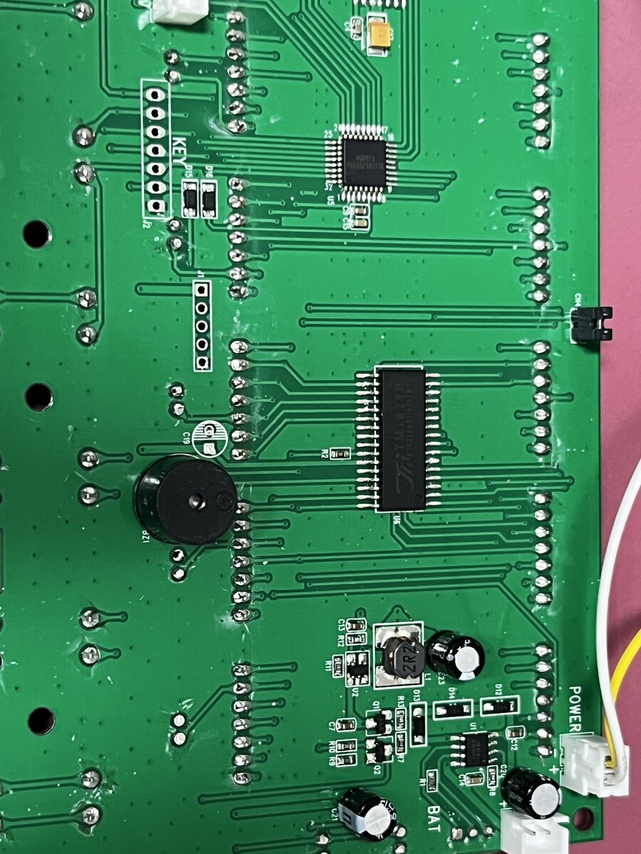
würde irgendetwas ihn im Reset halten. Das einzige, was nach Resetschaltung ausschaut, sind zwei SOT-23 direkt neben dem Controller. Dort messe ich seltsame und langsam umher driftende Spannungen. Habe die beiden SOT-23 ausgelötet - interessanter Weise hat das dazu geführt, dass der Controller bootet und
Abbildung präsentiert. 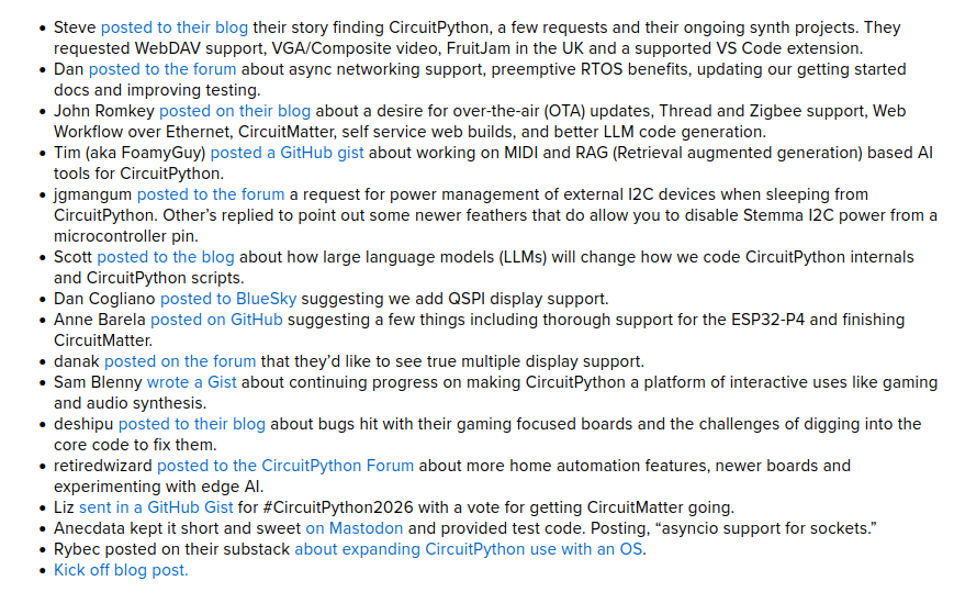 Bildquelle: https://blog.adafruit.com/2026/01/23/circuitpython2026-wrap-up/ ### Fraunhofer IPMS - HfO₂-basierte Speicher für den AI-Einsatz Zu guter Letzt noch eine Meldung des Fraunhofer Instituts, die - nach folgendem Schema - über angewandte
### Lesestoff: Wenn die Drohne einen Roboter abwirft. Unter der URL https://dronelife.com/2026/01/23/when-drones-deliver-robots-what-layered-autonomy-signals-for-the-future-of-uncrewed-systems/ findet sich ein durchaus inspirierender Artikel, der auf eine „neuartige“ Art und Weise des Drohneneinsatzes
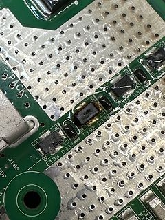
find ich gerade keine wo ich sicher sagen kann "mit höchster Wahrscheinlichkeit diese". J2t SOT-23 könnte es sein: MMBZ5V6ALT1 https://alltransistors.com/file_download.php?doc=mmbz5v6alt1rev1&dire=11&sup=on&id=2f92df841bf09f182d5adbd262b40fa1
glücklicherweise die Platine 2x. Aber das marking ist komplett Unterschiedlich. Gehäuse müsste SOT-23-5 sein. Nr. 1 - VTU Nr.2 - 8S08B Leider habe ich in den üblichen Marking Codes Datenbanken nichts dazu finden können. Und entschuldigt, dass das eine Bild so schlecht ist. Danke für eure
Code auf dem Bauteil lautet GB s 49 . Soweit ich rausgefunden habe, handelt es sich um ein SOT-23 Gehäuse. Kann mir jemand sagen welches Teil ich anstelle diesem einbauen kann und wo ich dass dann vielleicht sogar herbekomme? Das würde mir helfen viel Geld zu sparen und ich bedanke mich schon
The • up to 97% Efficiency SDB628 includes under-voltage lockout, current • Available in a 6-Pin SOT23-6 Package limiting, and thermal overload protection to prevent damage in the event of an output overload. The SDB628 is available in a small 6-pin SOT-23 APPLICATIONS package. • Battery-Powered Equipment
The z up to 93% Efficiency MT3608 includes under-voltage lockout, current z Available in a 6-Pin SOT23-6 Package limiting, and thermal overload protection to prevent damage in the event of an output overload. The MT3608 is available in a small 6-pin SOT-23 APPLICATIONS package. z Battery-Powered Equipment

 Bild
Bild
 Bild
Bild
 Bild
Bild
 Bild
Bild
 Bild
Bild
 Bild
Bild
 Bild
Bild
 Bild
Bild
 Bild
Bild
 Bild
Bild

 Bild
Bild
 Bild
Bild