-
PDF
Viper12a.pdf
VIPER12A-E Package mechanical data Table 10. DIP8 mechanical data Databook (mm) Ref. Min. Nom. Max. A 5.33 A1 0.38 A2 2.92 3.30 4.95 b 0.36 0.46 0.56 b2 1.14 1.52 1.78 c 0.20 0.25 0.36 D 9.02 9.27 10.16 E 7.62 7.87 8.26 E1 6.10 6.35 7.11 e 2.54 eA 7.62 eB 10.92 L 2.92 3.30 3.81 Package Weight Gr. 470 Figure 16. Package dimensions Doc ID 11977 Rev 2 17/21 Package mechanical data VIPER12A-E Table 11. SO8 mechanical data Databook (mm) Dim. Nom Min Max A 1.35 1.75 A1 0.10 0.25 A2 1.10 1.65 B 0.33 0.51 C 0.19 0.25 D 4.80 5.00 E 3.80 4.00 e 1.27 H 5.80 6.20 h 0.25 0.50 L 0.40 1.27 k 8° (max.) ddd 0.1
in „Reparatur Netzteil elektrischer Kamin“ · Analoge Elektronik und Schaltungstechnik ·
-
Artikel
AVR-GCC-Tutorial
der AVR-LibC Abschnitt Modules/Special Function Registers Bitmanipulation 16-Bit Register (ADC, ICR1, OCR1x, TCNT1, UBRR). Einige der Portregister in den AVR-Controllern sind 16 Bit breit. Im Datenblatt sind diese Register üblicherweise mit dem Suffix "L" (Low-Byte) und "H" (High-Byte) versehen. Die
als auch beim ADC – werden vom C-Compiler 16-Bit Pseudo-Register zur Verfügung gestellt (z. B. TCNT1H/TCNT1L → TCNT1, ADCH/ADCL → ADC bzw. ADCW), bei deren Verwendung der Compiler automatisch die richtige Zugriffsreihenfolge regelt. In C-Programmen sollten grundsätzlich diese 16-Bit-Register verwendet
Artikel ·
-
Artikel
STM32
M0+ bis 32 MHz - mit EEPROM STM32L1 (2010) ARM Cortex M3 bis 32 MHz - mit EEPROM STM32U0 (2024) ARM Cortex M0+ bis 56 MHz STM32L4 (2015) ARM Cortex M4F bis 80 MHz STM32U3 (2025) ARM Cortex M33F bis 96 MHz STM32L4+ (2017) ARM Cortex M4F
dem Board gepatcht werden. Für einen Test geht es auch mit Tastern für RESET und BOOT0. RESET=RTS (L-aktiv) BOOT0=DTR (H-aktiv) BOOT1=LOW Details sind hier im Forum: STM32 Programmiertool Tools für den Download über den STM32-Bootloader: STSW-MCU005 STM32 and STM8 Flash loader demonstrator stm32flash
Artikel ·
-
PDF
CD2003.pdf
Test Turns Freque L CO Wire Coil No. ncy (uH Q O (pF) 1-2 2-3 1-3 1-4 4-6 (mm) Reference (HZ) ) L1: 0258-0000 FM RF 100M 100 2.25 0.5 -021(注) L2: 0258-000 100M 100 1.75 0.5 FM OSC -020(注) L3: 2157-2239 796K 268 125 14 86 0.06 AM OSC -213A(注) NOTE: SUMIDA ELECTRIC CO., LTD V.C 3 4 3 pin12 2 1 6 1 Vcc L3 L1 L2 Version:2008-07-A WUXI CHINA RESOURCES SEMICO CO.,LTD. Page: 4/7 CD2003GP/GB 5. Application Circuit 6、Package Outline 6. 1、DIP16 Version:2008-07-A WUXI CHINA RESOURCES SEMICO CO.,LTD
in „Fledermausdetektor mit CD2003GB - Fragen zur Pin-Beschaltung“ · Analoge Elektronik und Schaltungstechnik ·
-
PDF
CD2003_WUXI_2008-07.pdf
Test Turns Freque L CO Wire Coil No. ncy (uH Q O (pF) 1-2 2-3 1-3 1-4 4-6 (mm) Reference (HZ) ) L1: 0258-0000 FM RF 100M 100 2.25 0.5 -021(注) L2: 0258-000 100M 100 1.75 0.5 FM OSC -020(注) L3: 2157-2239 796K 268 125 14 86 0.06 AM OSC -213A(注) NOTE: SUMIDA ELECTRIC CO., LTD V.C 3 4 3 pin12 2 1 6 1 Vcc L3 L1 L2 Version:2008-07-A WUXI CHINA RESOURCES SEMICO CO.,LTD. Page: 4/7 CD2003GP/GB 5. Application Circuit 6、Package Outline 6. 1、DIP16 Version:2008-07-A WUXI CHINA RESOURCES SEMICO CO.,LTD
in „Wie wird ein TO-50-Transistor auf einem Steckbrett angebracht?“ · Analoge Elektronik und Schaltungstechnik ·
-
PDF
MP900-SERIES_ENG_TDS.pdf
or a metal clip in contact with the top (2.39 ±.10).DIA(8.12 ±.26) (2.79 ±.26) surface of the part. L + .440 ±.010 Insulation Resistance: 10,000 Megohms min. (11.18 ±.26) The resistor element is electrically isolated from (2.03 ±.51) M0.10Ω (2.92 ±.26) the mounting surface. Figure 1 1% TO-126 Style .053 ± .007 .450 ±.050 (1.35 ± .18) Load Stability: 2,000 hours at rated power. MP915 (11.43 ±1.27) .030 ±.004 ΔR ±(1.0 percent + 0.0005 ohm) max. Power (.76 ± .10) rating dependent upon case temperature. See .200 ±.010 .025
in „Suchstrategie Isolierter NPN Leistungstransistor“ · Analoge Elektronik und Schaltungstechnik ·
-
Datei
stm8s.h
#define TIM1_RCR *(unsigned char*)0x5264 #define TIM1_CCR1H *(unsigned char*)0x5265 #define TIM1_CCR1L *(unsigned char*)0x5266 #define TIM1_CCR2H *(unsigned char*)0x5267 #define TIM1_CCR2L *(unsigned char*)0x5268 #define TIM1_CCR3H *(unsigned char*)0x5269 #define TIM1_CCR3L *(unsigned char*)0x526A #define TIM1_CCR4H *(unsigned char*)0x526B #define TIM1_CCR4L *(unsigned char*)0x526C #define TIM1_BKR *(unsigned char*)0x526D
in „I2C Display einfache Frage“ · Mikrocontroller und Digitale Elektronik ·
-
Thread
ESP32-S31-Module verfügbar, WiFi HaLow am Vormarsch, uptonitische Quartalszahlen uvam
www.youtube.com/watch?v=-YYkeAiIejI) oft schneller. Vor wenigen Stunden kündigte man mit dem WT0132S31-S1 ein erstes Modul an, auf dem einer der neuartigen ESP32-S31-Kernen verbaut ist.  Bildquelle, alle: Wireless-Tag Interessant ist, dass die Ankündigung - massiv
BeagleV Ahead and Lichee Pi 4a. The BeagleV Ahead board uses an AP6203BM WiFi module connected to SDIO1. The Lichee Pi 4A has an RTL8723DS WiFi module also connected to SDIO1. The module reset line is driven through a PCA9557 GPIO expander on the I2C1 bus. --- https://lore.kernel.org/lkml/ah4lkWh2eD6l7W7n
Mikrocontroller und Digitale Elektronik ·Tam H. · ·1 Antworten
-
PDF
Feuerhand_Beat_Lantern_Masterplan.pdf
Bassband ca. 45-180 Hz Bedienung ON/OFF unten; originaler Dochtknopf ueber 24-Rastungen-Encoder Akku 1x geschuetzter Keeppower P2160TC 21700, 6000 mAh / 21.6 Wh, USB-C Laden 5 V USB-C, ca. 1.5 A; Herstellerwert ca. 4 h, Ziel praxisnah 4-5 h Laufzeit Entwicklungsziel 7-8 h im gemischten Musikbetrieb Modi
in „Auftragsarbeit gesucht: ESP32 / RGBW / Audio-Reactive Feuerhand-Umbau“ · Markt ·
-
PDF
IIe_2523002_DMA_Hardware_Protocol.pdf
space, it might not be able to read the same data back. Apple IIe #2: Hardware Protocol for Doing DMA 1 of 9 Apple II Technical Notes H 4 T C 2 A A L D L 7 A O A A H D T D T V D A L N A E T S T S D U O I E B / D C m I V I r D C g L M M i O R D C X c 8 U L l A U A B S I E S a U H O n R I L t - D 7 E S c 0 A ( L P u D M O F ( A T e U R O I B K M C l T 6 R D 5 p A A S A A L G L - 1 A I N A e R I I T ( u T R D U T S N U U i I A K M M C B F B M T I S Y N C E K E D O D R A F - O E R 7 4 L S 2 4 4 2 5 6 2 of 9 Developer
in „Apple ][ DMA Timing“ · Mikrocontroller und Digitale Elektronik ·
-
PDF
C462925.pdf
2.19 2.38 Z D 0.020 0.028 0.51 0.71 A E 0.018 0.023 0.46 0.58 S 1 2 3 4 5 F 0.024 0.032 0.61 0.81 G 0.180 BSC 4.56 BSC U H 0.034 0.040 0.87 1.01 K J 0.018 0.023 0.46 0.58 F K 0.102 0.114 2.60 2.89 J L 0.045 BSC 1.14 BSC R 0.170 0.190 4.32 4.83 L H R1 0.185 0.210 4.70
in „Verpolungsschutz“ · Analoge Elektronik und Schaltungstechnik ·
-
Datei
oled_2313demo.c
- XCK - INT0 PD2 | 6 i 15 | PB3 - OC1A - PCINT3 INT1 - PD3 | 7 n 14 | PB2 - OC0A - PCINT2 T0 - PD4 | 8 y 13 | PB1 - AIN1 - PCINT1 OC0B - T1 - PD5 | 9 12 | PB0 - AIN0 - PCINT0 GND | 10 11 | PD6 - ICP +-------------+ */ #include <stdint.h>
in „I2C Display einfache Frage“ · Mikrocontroller und Digitale Elektronik ·
-
PDF
T2117_Atmel.pdf
with Definite Reduction (Remote Control) for a Temperature Range of 5 to 30°C L -∆T R 0.35 ... 1 R 4 Load 1.5 kW 510 kΩ 680 kΩ R V M 230 V ~ 5 680 kΩ R 2 R3 13 kΩ/2 W H = 50 mA 62 Ω N R 16 8 7 6 5 220 kΩ R 6 T2117 9.1 kΩ R 7 1 2 3 4 12 kΩ R 10 C R 15 910 kΩ 3 25 kΩ R9 10 nF C 1 NTC 12 kΩ 33 kΩ 2.2 µF C5 100 µF/ C 4 R8 C 2 12 V 47 µF 56 kΩ 1 µF 11 4768B–INDCO–10/05 Figure 10-5. Two-point Temperature Control for a Temperature Range of 15°C to 30°C L Load/1000 W 220 kΩ VM= 230 V ~ 18 kΩ/ 1.5 W VDR 56 Ω N 8 7 6 5 220 kΩ (680 kΩ) T2117 500 kΩ
-
Datei
Giga_009.ino
// Programm für Arduino Giga mit Bildschirm // Giga_009_Poti_Scala // LED_PR1 = D51/PE5, LED_PR2 = D40/PE6, PR1 = A11/PA0_C, PR2 = A10/PA1_C #include <Arduino_GigaDisplay_GFX.h> #include <Arduino_GigaDisplay.h> #include "Fonts/FreeMonoBold18pt7b.h" GigaDisplay_GFX display; // create the object #include <farbe16.h> #define PR1 A11 #define PR2 A10 #define LED_PR1 51 #define LED_PR2 40 #define DRE_A 35 #define DRE_B 36 #define DRE_KN 34 #define GIGA_RED 86 #define GIGA_GREEN 87 #define GIGA_BLUE 88 // Einstellungen
in „Arduino GIGA + GigaDisplay Scala Problem“ · Mikrocontroller und Digitale Elektronik ·
-
Datei
Giga_008_Poti_Scala.ino
// Programm für Arduino Giga mit Bildschirm // Giga_008_Poti_Scala // LED_PR1 = D51/PE5, LED_PR2 = D40/PE6, PR1 = A11/PA0_C, PR2 = A10/PA1_C #include <Arduino_GigaDisplay_GFX.h> #include <Arduino_GigaDisplay.h> #include "Fonts/FreeMonoBold18pt7b.h" GigaDisplay_GFX display; // create the object #include <farbe16.h> #define PR1 A11 #define PR2 A10 #define LED_PR1 51 #define LED_PR2 40 #define DRE_A 35 #define DRE_B 36 #define DRE_KN 34 #define GIGA_RED 86 #define GIGA_GREEN 87 #define GIGA_BLUE 88 // Einstellungen
in „Arduino GIGA + GigaDisplay Scala Problem“ · Mikrocontroller und Digitale Elektronik ·
-
Datei
Controler2.cpp
#include <avr/io.h> #include <stdio.h> #include <util/delay.h> #include <string.h> #include <stdlib.h> #include <avr/interrupt.h> #include <LiquidCrystal.h> using namespace std; LiquidCrystal lcd(12, 11, 5, 4, 3, 2); /
in „Kommunikation zwischen 2 MC“ · Mikrocontroller und Digitale Elektronik ·
-
PDF
PSE1800_a-_Schaltplaene.pdf
<> ___DATEN-BUS | D¢...D7 { foe..07 { Yoo... yD1 CS3(CS4) OF “EPROM | Peripheriebaustein Peripheriebaustein | , io IS2 om 1S1 i ! Timer- 1/0 - Ports |/0 -Ports Fi oe a Ausg. A BC ane, i es AD cee lS rf =ac Baustein- > Auswahl Doppel- \S7 D-Latch IS9
in „AEG - Telefunken E1800 mit PIO 1200 Schnittstelle.“ · Mikrocontroller und Digitale Elektronik ·
-
Datei
stxuartlcd_demo_all.ino
(2000); stxlcd.printf("\rvorne"); delay(2000); stxlcd.clrscr(); stxlcd.gotoxy(1,1); stxlcd.printf("%l UserChars"); stxlcd.senduserchar(1, &charbmp1[0]); stxlcd.senduserchar(2, &charbmp2[0]); for (i= 0; i< 5; i++) { stxlcd.printf("%p%P%c%c",10,2,1,2); delay(200); stxlcd.printf("%
in „Arduino: serielles Ansprechen eines HD44780 Displays über SoftSerial“ · Projekte & Code ·
-
PDF
C22446452.pdf
RSENSE CH- P- 图 6 Rev 1.1 深圳市创芯微微电子股份有限公司 11 / 16 CM1052 系列 BOM 清单 器件标识 典型值 参数范围 单位 RVCCR VC1~ VC5 1 0.33 ~ 2 kΩ RNTC 100k @25°C − Ω RT 3*RNTC@T CH − Ω R 10 1 ~ 100 kΩ VINI R VM 10 1 ~ 50 kΩ R CO 10 3.3 ~ 15 MΩ R DO 1 0 ~
in „Einhell elektronik vom 18V Akkupack reparieren?“ · Analoge Elektronik und Schaltungstechnik ·
-
Datei
font_graph.c
, // 72 = 0x48 <H> 0x0E,0x04,0x04,0x04,0x04,0x04,0x0E,0x00, // 73 = 0x49 <I> 0x1C,0x08,0x08,0x08,0x08,0x09,0x06,0x00, // 74 = 0x4a <J> 0x11,0x09,0x05,0x03,0x05,0x09,0x11,0x00, // 75 = 0x4b <K> 0x01,0x01,0x01,0x01,0x01,0x01,0x1F,0x00, // 76 = 0x4c <L> 0x11,0x1B,0x15,0x15,0x11,0x11,0x11,0x00, // 77 = 0x4d <M> 0x11,0x11,0x13,0x15,0x19,0x11,0x11,0x00, // 78 = 0x4e <N> 0x0E,0x11,0x11,0x11,0x11,0x11,0x0E,0x00, // 79 = 0x4f <O> 0x0F,0x11,0x11,0x0F,0x01,0x01,0x01,0x00
in „Lib für Arduino Giga machen“ · Mikrocontroller und Digitale Elektronik ·
-
Bild
Zwei STM32 Nucleo Mikrocontroller-Boards
LD1, CN1, ST, T17T, SB1, R1, R2, U1, R10, C2, C3, SB2, R13, C5, R14, SB3, R15, R18, U2, C4, C11, X1, C14, LD2, 2180H, 221B, LD3, SB1, CN2, C19, U4, R17, C18, R20, CN3+, U5, C1, C2, MB1180 Rev A, SB11, SB10, L1, SB12, C24, SB13, D4, R22
in „CH32V003 und Arduino“ · Mikrocontroller und Digitale Elektronik · · Platinenfotos
-
Bild
Oszilloskop-Screenshot eines Rauschsignals
MSO5074 Wed November 12 14:31:15 2025 RIGOL STOP H 2.00us 8GSa/s 160kpts Measure STOP/RUN D 780ns T 1 2.08V A VRMS1 3.4267V Vpp1 1.4614V +Width1 9.2135us 1 2.00V 2 5.00V -11.8V 3 5.00V -1.80V 4 20.0mV 0.00V L 0 1 2 3 4 5 6 7 8 9 10 11 12 13 14 15 GI
in „Ethernet - Problem mit LAN8742“ · Mikrocontroller und Digitale Elektronik · · Oszi-Bilder
-
PDF
tpp30a-d.pdf
EN 61000-4-3, 20 V/m, perf. criteria A - EFT (Burst) / Surge EN 61000-4-4, ±2 kV, perf. criteria A L to L:EN 61000-4-5, ±1 kV, perf. criteria A - Conducted RF Disturbances EN 61000-4-6, 20 Vrms, perf. criteria A - PF Magnetic Field Continuous: EN 61000-4-8, 30 A/m, perf. criteria A - Voltage Dips & Interruptions 230 VAC / 50 Hz: EN 61000-4-11 30%, 25 periods, perf. criteria A 60%, 1 period, perf. criteria A >95%, 1 period, perf. criteria A >95%, 250 periods, perf. criteria A 115 VAC / 60 Hz: EN 61000-4-11 30%, 25 periods, perf. criteria A
in „Komponenten für Low Power Fileserver?“ · PC Hard- und Software ·
-
PDF
4012002220-__IC_MT3608_SMD_SOT23-6L_AEROSEMI_.pdf
Routers z Networking cards powered from PCI or PCI express slots TYPICAL APPLICATION 100 VOUT5V 95 VIN L 4.7μH D VOUT ) 90 VIN SW ( CIN MT3608 110k COUT n 85 22μF 1% 22μF i EN FB E GND R2 80 VIN=3V 11% VIN=3.7V 75 VIN=4.2V 70 0 200 400 600 800 1000 Figure 1. Basic Application Circuit Load Current(mA) MT3608
in „SMD Bauteilidentifizierung (B6282)“ · Analoge Elektronik und Schaltungstechnik ·
-
PDF
LTspice_IV_Tutorial_Tritschler_Kloenne.pdf
folgen. Daher können Multiplikatoren verwendet werden. Es gilt: 1 Millivolt = 1m = 1mV = 1e-3 = 1e-3V Hierbei können jeweils der erste Buchstabe des jeweiligen Multiplikators verwendet (k: Kilo, u: Mikro, p: Pico, f: Femto, usw.). Einzige Ausnahme ist der Multiplikator
in „Ltspice Funktionsbaustein erstellen?“ · Analoge Elektronik und Schaltungstechnik ·
-
Bild
Oszilloskop-Messung einer Signalspitze
MSO5074 Wed November 12 14:29:30 2025 RIGOL STOP H 2.00us 8GSa/s 160kpts Measure STOP/RUN D 780ns T 1 2.08V A VRMS1 3.3501V Vpp1 3.4709V +Width1 ***** 1 2.00V 2 5.00V -11.8V 3 5.00V -1.80V 4 20.0mV 0.00V L 0 1 2 3 4 5 6 7 8 9 10 11 12 13 14 15 GI GII
in „Ethernet - Problem mit LAN8742“ · Mikrocontroller und Digitale Elektronik · · Oszi-Bilder
-
PDF
RS-25-SPEC.pdf
(L*W*H) 0.2Kg; 60pcs/13Kg/0.46CUFT PACKING 1. All parameters NOT specially mentioned are measured at 230VAC input, rated loa℃ of ambient temperature. NOTE 2. Ripple & noise are measured at 20MHz of bandwidth
in „Willtek Schlumberger Stabilock 4031 4032“ · HF, Funk und Felder ·
-
PDF
AVX-TC.pdf
case products are as shown below. UNDERTAB M CASE CASE DIMENSIONS: millimeters (inches) Code EIA EIA L±0.10 W±0.10 H±0.10 W1±0.10 A±0.10 Code Metric (0.004) (0.004) (0.004) (0.004) (0.004) M 0603 1608-09 1.60 (0.063) 0.85 (0.033) 0.80 (0.031) 0.55 (0.022) 0.50 (0.020) J-LEAD A, P CASE CASE DIMENSIONS: millimeters (inches) Code EIA EIA L±0.20 W±0.20 H±0.20 (0.008) W1±0.20 A±0.30 Code Metric (0.008) (0.008) (0.008) (0.012) A 1206 3216-18 3.20 (0.126)1.60 (0.063) 1.60 (0.063) 1.20 (0.047)0.80 (0.031) P 0805 2012-12 2.00 (0.079) 1.25 (0.049
in „Bosch E Bike Display Intuvia Diode zerstört bei Akkureparatur“ · Fahrzeugelektronik ·
-
Datei
asmjbt3.a51
;EF -- '' DB 0x86 ;86 -- '' DB 0xEF ;EF -- '' DB 0x7E ;7E -- '~' DB 0xEF ;EF -- '' DB 0x6C ;6C -- 'l' DB 0x00 ;00 -- '' DB 0x00 ;00 -- '' DB 0x00 ;00 -- '' DB 0x11 ;11 -- '' DB 0x00 ;00 -- '' DB 0x1E ;1E -- '' DB 0x00 ;00 -- '' DB 0x32 ;32 -- '2' DB 0x00 ;00 -- '' DB 0x41 ;41 -- 'A' DB 0x00 ;00 -- '
in „Eprom von Denon DJ Laufwerk defekt Winbond 78e52“ · Mikrocontroller und Digitale Elektronik ·
-
Datei
oled_demo.c
mit SDCC Compiler ------------------------------------------------------------ */ #include "stm8s.h" // PB4 I/O #define PB4_output_init() { PB_DDR |= 0x10; \ PB_CR1 |= 0x10; \ PB_CR2 &= ~(0x10); } #define PB4_clr() ( PB_ODR &= ~(0x10) ) #define PB4_input_init() { PB_DDR &= ~(0x10); \ PB_CR1 |= 0x10
in „I2C Display einfache Frage“ · Mikrocontroller und Digitale Elektronik ·
-
PDF
44-vish.pdf
Soldering Recommendations (Peak Temperature) for 10 s 300 Mounting Torque 6-32 or M3 screw 10 lbf · in 1.1 N · m Notes a. Repetitive rating; pulse width limited by maximum junction temperature (see fig. 11). b. VDD = 25 V, startinJ T = 25 °C, L = 179 gH, R = 2ASΩ= 51 A (see fig. 12). c. I ≤ 51 A, dV/dt
in „Aus Minus Plus machen?“ · Analoge Elektronik und Schaltungstechnik ·
-
PDF
PCB.pdf
IO14+5V GND U9 GND IO16U4 R8 U5 C5 1 R7 W R11 R3 S U2 C6 C 1 - R2 A C2 S L C S D11 N D G N I G V + V + 1U U8 R4 1 U C3 R6 R10 U12 C U7 4H1 R5 R9 R12 R1 GNDIO0 +3.3GND RX TX U3 U6IO125V GND GND +5V IO13 41U 31U U16 U15
in „Feedback 1. Projekt PCB-Design (Roboter-Hund)“ · Platinen ·
-
Bild
Handschriftlicher Schaltplan eines Amplitudenmodulators
+9V Blockbatterie Amplitudenmodulator C1 100uF R1 11,16 MHz 11 10 CD4060 Vcc Clk. Q0 7 697,5kHz R2 3k9 C3 10n Q1 BC548 Ausgang C6 10n C4 330p C5 330p L1 100uH GND Res. 8 12 C2 150pF R3 10k Modulations-eingang C7 100uF R4 100R Masse
in „Wie baut man eine Endstufe für einen Mittelwellensender (160m Band)?“ · HF, Funk und Felder · · Schaltpläne
-
Bild
Schaltplan eines Schaltreglers
Power supply input 12V dc, 1A Center pin is + J1 PJ-063AH 12V C4 100uF 35V F 12V C7 100uF 35V F 12V C10 10uF 0805 2mR 12V L1 10uH 7070 3,5A 33mR U2 LT8365 16 SW1 14 SW2 3 VIN 17 GND 1 ENABLE_UA 12 EN/UVLO SYNC/MODE 10 RT 11 SS 5
in „klassischer Step Up in Verbindung mit Spannungsvervielfacher dahinter - Erfahrungswerte?“ · Analoge Elektronik und Schaltungstechnik · · Schaltpläne
-
Datei
MSP3400_ATMEGA32_ADC_2.ino
0x12, 0, 0x0F, 0, 0x3F); TWI_MSP(0x12, 0, 0x12, 0x10, 0); TWI_MSP(0x12, 0, 0x16, 0x10, 0); uint8_t h = volumeSpeaker >> 8; uint8_t l = volumeSpeaker & 0xFF; TWI_MSP(0x12, 0, 0x07, h, l); TWI_MSP(0x12, 0, 0x00, h, l); TWI_MSP(0x12, 0, 0x13, 0x14, 0); // BEEP TWI_MSP(0x12, 0x00, 0x14, 0x60, 0x40); delay
in „Zeigt her eure Kunstwerke (ab 2023)“ · Projekte & Code ·
-
Datei
MSP3400_ATMEGA32_ADC_2.ino
0x12, 0, 0x0F, 0, 0x3F); TWI_MSP(0x12, 0, 0x12, 0x10, 0); TWI_MSP(0x12, 0, 0x16, 0x10, 0); uint8_t h = volumeSpeaker >> 8; uint8_t l = volumeSpeaker & 0xFF; TWI_MSP(0x12, 0, 0x07, h, l); TWI_MSP(0x12, 0, 0x00, h, l); TWI_MSP(0x12, 0, 0x13, 0x14, 0); // BEEP TWI_MSP(0x12, 0x00, 0x14, 0x60, 0x40); delay
in „AUDIOCONTROLLER MSP3400C einfach mit ATMEGA32 ansteuern“ · Projekte & Code ·
-
PDF
Bauteile.pdf
g u 0 n l t r p t n t t t t e k 1 2 a / N T A i a a a a a e i i n e z S S S S S e B B A P B B 1 2 Bauteil 74xxxx 74HC374ADW SMD 8BitFlipFlop 24 0,30€ 3 Bauteil 74xxxx 74HCT161 SMD Counter 30 0,70€ 4 Bauteil 74xxxx
-
Bild
Display eines Rigol MSO5152-E Oszilloskops mit Optionsliste
RIGOL MSO5152-E DIGITAL OSCILLOSCOPE UltraVision 2 Channel 150MHz 4GSa/s RIGOL AUTO H 500ns 4GSa/s 20kpts Measure STOP/RUN D 0.00s Option list Name Licence Info 1RL Forever 100Mpts Deep Memory Option COMP Forever Computer Serial Triggering and Analysis(RS232/UART) EMBD Forever Embedded
in „[V]Rigol Oszilloskop MSO5152-E, 2 Kanal, USB.LAN und HDMI Anscluss“ · Markt · · Fotos
-
Bild
Schaltplan eines Universal-Eingangs-Netzteils
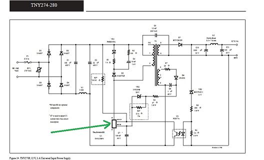
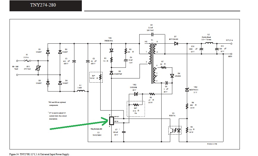
TNY274-280 F1 2.15 A DS 1N4007 D1 1N4007 D2 1N4007 C1 68 uF 400 V C2 2.2 uF 250 VAC C3 1000 uF 25 V C4 100 uF 16 V C5 1 uF 50 V C6 100 uF 25 V C7 100 uF 50 V C8 100 uF 50 V C9 1 uF 50 V C10 1000 uF 25 V C11 100 uF 16 V D3 1N4007 D4 1N4007 D5 1N4007GP D6 1N4002 D7 ZVYB2-300 L1 1 mH L2 Power Ind 2.5 x 7.5 mm Q1 PSKE150A Q2 INFS56 Q3 TNY278P R1 1 k R2 100 Ω R3 1 k R4 22 k R5 2.63 Ω R6 200 Ω R7 22 Ω RTN Figure 14. TNY278P,
in „ungeglättetes Schaltnetzteil“ · Analoge Elektronik und Schaltungstechnik · · Schaltpläne
-
Artikel
CAN
Anstiegszeit des TX-Signals zu schlecht ist. Freescale MC9S08. D Serie Freescale MC9S12. B, C, D, G und H Serie NXP LPC11CXX. 32-bit ARM Cortex-M0 LPC11C12 16KB flash, 8KB SRAM, 1x C_CAN LPC11C14 32KB flash, 8KB SRAM, 1x C_CAN LPC11C22 16KB flash, 8KB SRAM, 1x C_CAN, on-chip CAN transceiver LPC11C24 32KB
MCUs STM32F042 : 1 CAN Schnittstelle STM32F072 : 1 CAN Schnittstelle Cortex M3 Core - STM32 F1 series of mainstream MCUs STM32F103 : 1 CAN Schnittstelle STM32F105 : 2 CAN Schnittstellen STM32F107 : 2 CAN Schnittstellen
Artikel ·
-
Bild
Schaltplan einer elektronischen Schaltung
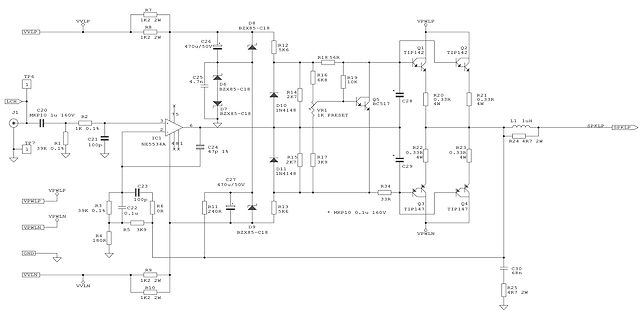
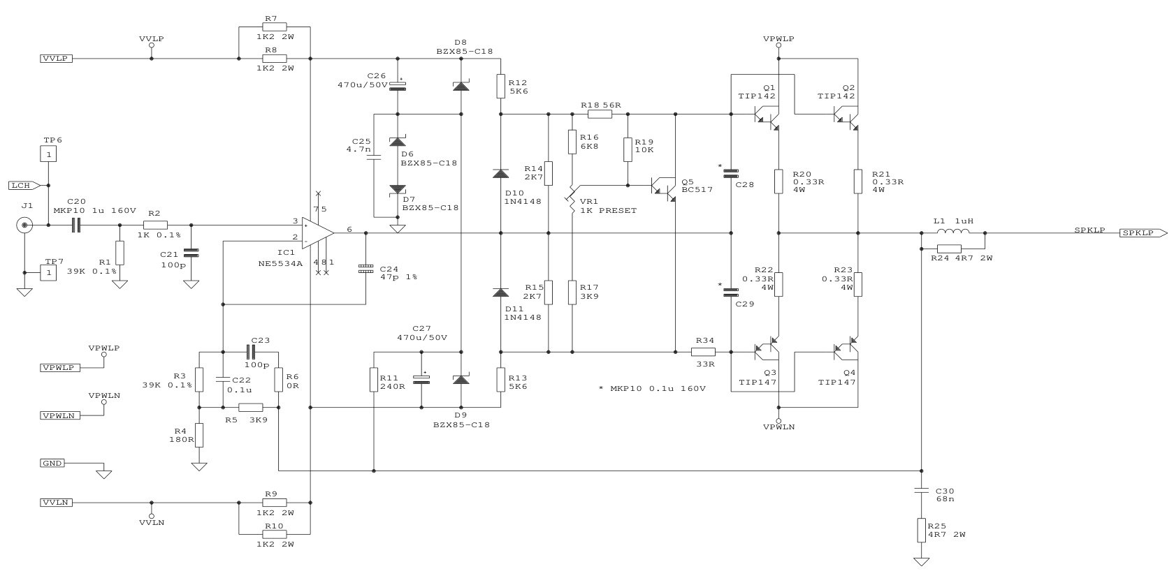
VVLP, R7, 1K2, 2W, C26, 470u/50V, D8, BZX85-C18, VPWLP, Q1, TIP142, Q2, TIP142, R20, 0.33R, 4W, R21, 0.33R, 4W, C28, L1, 1uH, SPKLP, R24, 4R7, 2W, R19, 10K, R16, 6K8, R18, 56R, R12, 5K6, D6, BZX85-C18, C25, 4.7n, R14, 2K7, D7, BZX85-C18, Q5, BC517, R17, 3K9, R15, 2K7, D10, 1N4148, R22, 0.33R, 4W, R23, 0.33R, 4W, C29, IC1, NE5534A, C21, 100p, R1, 39K, 0.1%, TP6, 1, LCH, J1, C20, MKP10, 1u 160V, R2, 1K, 0.1%, TP7, 1, 39K, 0.1%, C24, 47p, 1%, C27, 470u/50V, D11, 1N4148, R6,
in „Bootstrap OpAmp Schaltung für High Voltage Swing“ · Analoge Elektronik und Schaltungstechnik · · Schaltpläne
-
PDF
LDO_ME6211C33M5G.PDF
Battery powered equipment Package ● 3-pin SOT89-3,SOT23-3 ● 5-pin SOT23-5,SOT353 ● 6-pin DFN2*2-6L V14 www.microne.com.cn Page 1 of 20 ME6211 Typical Application Circuit Fig1. ME6211A series Fig2. ME6211C series Fig3. ME6211H series V14 www.microne.com.cn Page 2 of 20 ME6211 Selection Guide product
in „ESP32-H2 will nicht schlafen“ · Mikrocontroller und Digitale Elektronik ·
-
PDF
RS-50-spec.pdf
*36mm (L*W*H) PACKING 0.41Kg; 45pcs/19.5Kg/0.9CUFT NOTE 1. All parameters NOT specially mentioned are measured at 230VAC input, rated load and 25℃ of ambient temperature. 2. Ripple & noise are measured at 20MHz
in „Willtek Schlumberger Stabilock 4031 4032“ · HF, Funk und Felder ·
-
Bild
Bauteilliste einer Elektronikkomponente
17V, 4.0A, 1MHz, Buck Converter IC1 VQFN-11(2x3) C2865220 Texas Instruments TPS62136RGXR PCB terminal block, 400V, 24A, 2.5mm2, 2 pins, pitch 5mm J1,J2 Plugin,P=5mm C5438430 Phoenix Contact 1711026 1.5uH, 21.45mΩ, 7.1A, 20%, Power Inductor L1 SMD, 4x4mm C18547833 Coilcraft XAL402021M47FKED 1.47mΩ, 62.5mW, 75V, ±1%, Thick Film Resistor R1 0402 C2085460 Vishay CRCW04021M47FKED 100kΩ, 50V, 63mW, ±1%, Thick Film Resistor
in „Bewertung und Feedback zu meinem 14.5V-to-11.0V DC-DC Buck Converter Design und PCB Layout (TPS6213)“ · Analoge Elektronik und Schaltungstechnik · · Screenshots
-
PDF
Datenblatt_NTE2349__NTE2350.pdf
▯▯▯▯ ▯▯ ▯▯▯▯ ▯▯!▯▯ ▯▯▯!▯ " #%’()+&’./12’()3&..&568:&:;%;10>?51:1016:61&A* >%<9B@&%@12:&6&6:=D2E961@1%0<5:%0;7%0<70:6F G▯▯▯" H 7$?JJ51&K1L (NO4&P1Q&JN3S $ N+4P7&QRN3S ( J H 72&5=9:&:T%2J H P17$&:159:&VD=RW0%(;=5YD1T66:5 H D9:&%;%0D%:[44J ]▯▯▯▯_‘a▯ab▯ ▯" J89:X;7%c:0%cJAFF O4c J89:X06c:0%&JW&F O4c (;%XW6&:0@&c &F 3c (W J89:JD%1&J J17DD6F 4S .0B & O4S J11DD&0%JD%1RFF )S W #0&:U&?6<=1-JN[3Jd.?F 44e ?5=&fE%3J&Q#J[O4J F Oge\J A%01@D171#;<5=%T0@d# F X3\:[4\J Z Y:0%#;<0D%T0@d6@FF X3\:[4\J #%;0T6609dD171=XJ6dTZJ&F Fh\J i0&%;%0D%?D1&
in „Darlington Transistoren mit internen Widerständen“ · Analoge Elektronik und Schaltungstechnik ·
-
PDF
TOFC100-xx.pdf
Digital output L Analog output There is an analog output pin in addition to the digital output from the receiving C : 0.1 µFC2 C1 : 0.1 µF InputCCGND VCC GND L : 47 µH µF module. Using this pin as an optical flux monitor
in „TosLink als einfacher Datenlink“ · Mikrocontroller und Digitale Elektronik ·
-
PDF
ME2108_Series.pdf
). A low ripple, high efficiency l Low start voltage≤0.9V(at Iout=1mA)ÿ▯ l Maximum oscillator frequencyÿ180KHz(Typ.) step-up DC/DC converter can be constructed of l High Efficiencyÿ85%(Type) ME2108Xxx wi th only three external components
in „Alle Jahre wieder: Fundstück in Weihnachtsbeleuchtung“ · Analoge Elektronik und Schaltungstechnik ·
-
PDF
RxxPxx.pdf
Audio/Video, information and communication technology equipment - EN62368-1: 2014 + A11:2017 Part1: Safety requirements ATTCB106076 Audio/Video, information and communication technology equipment - IEC62368-1:2014, 2nd Edition Part1: Safety requirements (CB Scheme) Medical electrical
in „Isolierte Spannungsversorgung“ · Analoge Elektronik und Schaltungstechnik ·
-
Bild
Runde Leiterplatte mit elektronischen Bauteilen
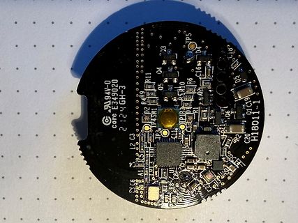
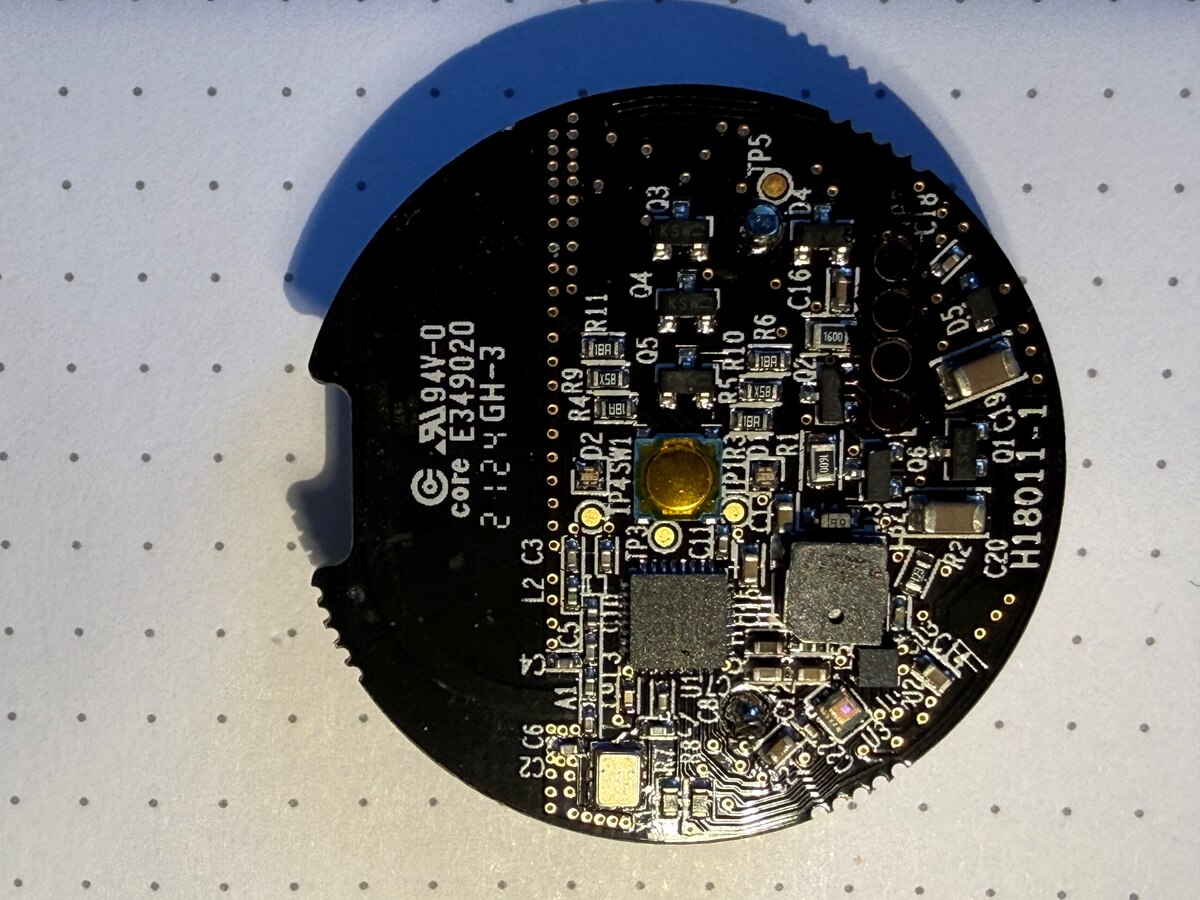
94V-0 core E349020 2124GH-3 TP5 Q3 TP4 SW1 R4 R9 R11 Q5 R5 R10 R6 R1 C16 1600 D5 D4 C19 Q1 C20 H18011-1 R2 C3 C6 L2 C1 C11 C14 C15 C18 C21 C22 C23 C24 C25 C26 C27 C28 C29 C30 C31 C32 C33 C34 C35 C36 C37 C38 C39 C40 C41 C42 C43 C44 C45 C46 C47
in „Wozu dient dieser Sensor?“ · Mikrocontroller und Digitale Elektronik · · Platinenfotos
-
PDF
01_ArchitectureExplorationofHigh-PerformanceFloating-PointFusedMultiply-Add.pdf
the other hand, the widths of the multiplication and addition stages grows significantly: a 5b and an 11b adder is so small (1.650ns vs. 1.742ns) The multiplier now has a (52+1)b wide multiplicand B that we can choose the more area efficient 11b distribution M without a significant performance penalty. In
in „Pipeline MAC-Unit: Problem mit Latency“ · FPGA, VHDL & Co. ·