-
Thread
Ich möchte aus einer Spannung einen binärcode erzeugen
Hardware habe ich einen Ardiuno UNO R3 verwendet. Falls es irritieren sollte: das Programm ist trotz .ino-Endung in C geschieben, < 1kB groß und kann einfach auf einen ATtiny44 gebracht werden.
Analoge Elektronik und Schaltungstechnik ·Thorsten P. · ·248 Antworten
-
 Bild
Bild
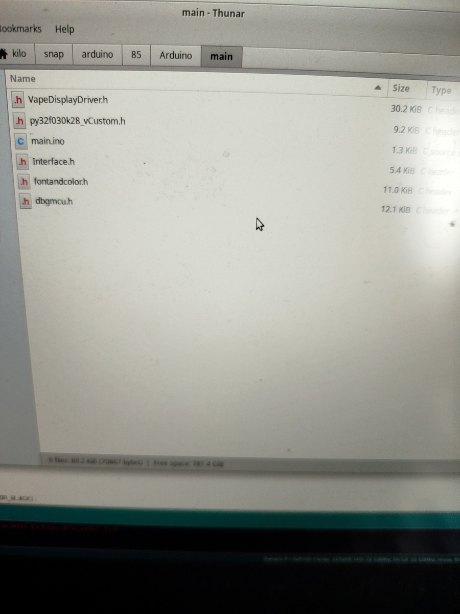
Dateiliste in einer Arduino-Entwicklungsumgebung
Size Type h VapeDisplayDriver.h 30.2 KiB C header h py32f030k28_vCustom.h 9.2 KiB C header c main.ino 1.3 KiB source c h Interface.h 5.4 KiB C header h fontandcolor.h 11.0 KiB C header h dbgmcu.h 12.1 KiB C header
in „Arduino und struct gefallen sich nicht !“ · Mikrocontroller und Digitale Elektronik · · Fotos
-
 Bild
Bild
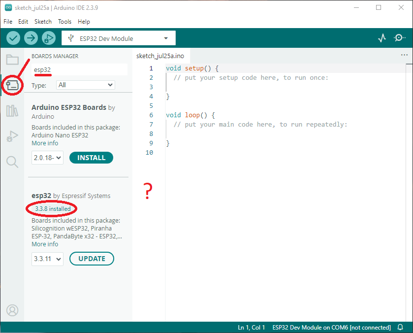
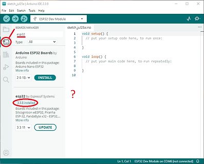
Arduino IDE Boards Manager mit ESP32 Installation
sketch_jul25a.ino void setup() { // put your setup code here, to run once; } void loop() { // put your main code here, repeatedly: } BOARDS MANAGER esp32 Type: All Arduino ESP32 Boards by Arduino Boards included in this
in „Keine änderung des BLE Namens des esp32c3“ · Offtopic · · Screenshots
-
 Bild
Bild
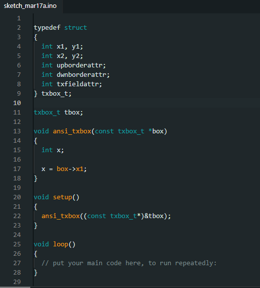
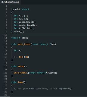
C++ Quellcode für eine Struktur und Funktion
sketch_mar17a.ino 1 2 typedef struct 3 { 4 int x1, y1; 5 int x2, y2; 6 int upborderattr; 7 int dwnborderattr; 8 int txfieldattr; 9 } txbox_t; 10 11 txbox_t tbox; 12 13 void ansi_txbox(const txbox_t *box) 14 { 15 int
in „Arduino und struct gefallen sich nicht !“ · Mikrocontroller und Digitale Elektronik · · Screenshots
-
 Bild
Bild
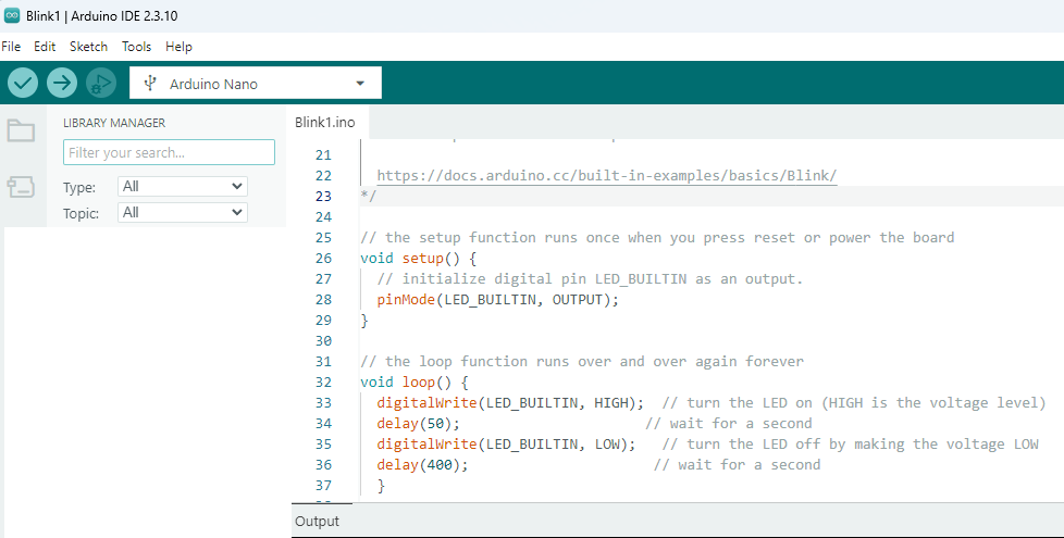
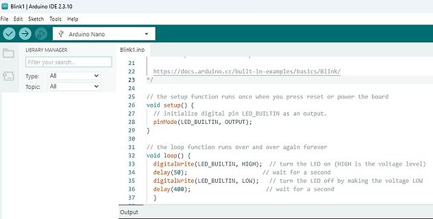
Arduino IDE Code für Blink-Beispiel
2.3.10 File Edit Sketch Tools Help LIBRARY MANAGER Filter your search... Type: All Topic: All Blink1.ino 21 22 https://docs.arduino.cc/built-in-examples/basics/Blink/ 23 /* 24 // the setup function runs once when you press reset or power the board 25 void setup() { 26 // initialize digital pin LED_BUILTIN
in „anfänger-Problem mit arduino“ · Mikrocontroller und Digitale Elektronik · · Screenshots
-
Datei
uart_tests2.ino
/* -------------------------------------------------------- uart_tests2.ino Demoprogramm fuer sehr rudimentaere UART (serial) Funktionen MCU : ch32v003 30.11.2025 R. Seelig -------------------------------------------------------- */ #include "v003_uart.h" V003uart uart; void
in „Arduino und CH32V003“ · Mikrocontroller und Digitale Elektronik ·
-
Datei
uart_tests2.ino
/* -------------------------------------------------------- uart_tests2.ino Demoprogramm fuer sehr rudimentaere UART (serial) Funktionen MCU : ch32v003 30.11.2025 R. Seelig -------------------------------------------------------- */ #include "v003_uart.h" V003uart uart; void
in „Arduino und CH32V003“ · Mikrocontroller und Digitale Elektronik ·
-
 Bild
Bild
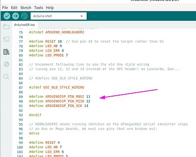
Programmcode eines ArduinoISP Sketches
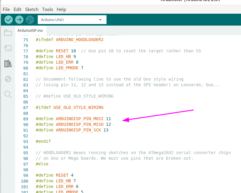
File Edit Sketch Tools Help Arduino UNO ArduinoISP.ino 75 #ifndef ARDUINO_HOODLOADER2 76 77 #define RESET 10 // Use pin 10 to reset the target rather than SS 78 #define LED_HB 9 79 #define LED_ERR 8 80 #define LED_PMODE 7 81 82 // Uncomment following line
in „Suche Arduino kompatiblen Bootloader für ATmega8 mit 8Mhz intern“ · Mikrocontroller und Digitale Elektronik · · Screenshots
-
Datei
stxuartlcd_demo0.ino
/* -------------------------------------------------------- stxuartlcd_demo0.ino Demosketch:Ansteuerung eines HD44780 kompatiblen Displays, welches über "stxlcdrecv_uart" angesteuert wird. Zeigt Verwendung der originalen Arduino-Methoden print / println in Verbindung mit Einlesen
in „Arduino: serielles Ansprechen eines HD44780 Displays über SoftSerial“ · Projekte & Code ·
-
 Bild
Bild
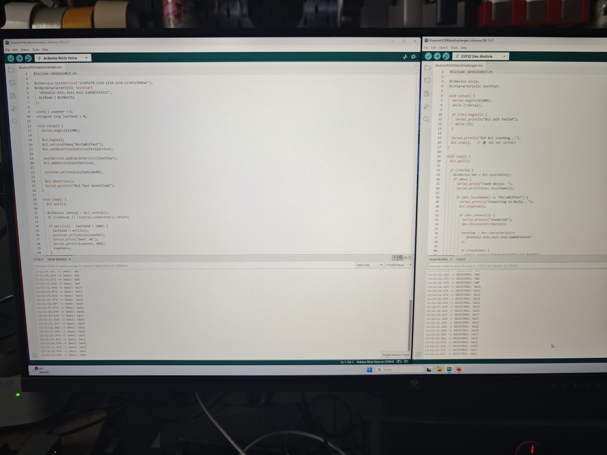
Foto eines Computerbildschirms mit Arduino-Code und Seriellem Monitor
Arduino Nilda Voice BluetoothBLEModule.ino #include <ArduinoBLE.h> void setup() { Serial.begin(115200); if (!BLE.begin()) { while (1); } BLE.setLocalName("BLE Test"); BLE.setAdvertisedService(service); BLE.addService(service); BLE.advertise(
in „Nicla Voice am ESP32“ · Projekte & Code · · Fotos
-
Datei
blink_int_v003.ino
/* ----------------------------------------------------- blink_int_v003.ino Blinkprogramm fuer CH32V003 mittels Interrupt Timer2 ----------------------------------------------------- */ #define LED PD5 /* -------------------------------------------------------- TIM2_IRQHandler
in „CH23V003 und Arduino: Verwendung Timer2 Interrupt“ · Projekte & Code ·
-
Datei
stxuartlcd_demo1.ino
/* -------------------------------------------------------- stxuartlcd_demo1.ino Demosketch:Ansteuerung eines HD44780 kompatiblen Displays, welches über "stxlcdrecv_uart" angesteuert wird. Zeigt Verwendung der originalen Arduino-Methoden print / println in Verbindung mit Einlesen
in „Arduino: serielles Ansprechen eines HD44780 Displays über SoftSerial“ · Projekte & Code ·
-
Datei
adc_demo.ino
/* -------------------------------------------------------- adc_demo.ino Demoprogramm zum Einlesen analoger Werte, hier 2 analoge Inputs 28.02.2026 R. Seelig -------------------------------------------------------- */ #include <Arduino.h> #include "v003_adc.h" // Objekte
in „CH32V003 und Arduino“ · Mikrocontroller und Digitale Elektronik ·
-
Datei
sr595_lauflicht_3.ino
/* Sketchname: sr595_lauflicht.ino Name: Max Mustermann Klasse: ITA-12B Ausbildungsberuf: Informationstechnischer Assistent Schularbeit: Lauflichtprojekt 1b Framework: Arduino */ #include <sn74hc595.h> // Pins für das Schieberegister
in „Schulnotenbewertung eines Arduino-Programms“ · Mikrocontroller und Digitale Elektronik ·
-
Datei
adc_ntc.ino
/* -------------------------------------------------------- adc_ntc.ino Demoprogramm zum Auslesen eines NTC-Widerstandes ueber einen analogen Eingang. 28.02.2026 R. Seelig -------------------------------------------------------- */ #include <Arduino.h> #include "v003_adc.h
in „CH32V003 und Arduino“ · Mikrocontroller und Digitale Elektronik ·
-
Datei
colpos_demo.ino
/* -------------------------------------------------------- colpos_demo.ino Demoprogramm fuer farbige Ausgabe auf einem seriellen Terminal MCU : ch32v003 12.11.2025 R. Seelig -------------------------------------------------------- */ #include "v003_colpos.h" #define cnt_speed
in „CH32V003 und Arduino“ · Mikrocontroller und Digitale Elektronik ·
-
Datei
sr595_lauflicht_1.ino
/* Sketchname "sr595_lauflicht.ino" [Ihr Name] [Ihre Schulklassenbezeichnung] [Ihr Ausbildungsberuf] Schularbeit: Lauflichtprojekt 1b Framework: Arduino */ // Include der Library #include "sn74hc595.h" // Pins definieren (anpassen an
in „Schulnotenbewertung eines Arduino-Programms“ · Mikrocontroller und Digitale Elektronik ·
-
Datei
adc_devel.ino
// adc_devel.ino #include <Arduino.h> #include "my_printf.h" #define printf my_printf // "Umleiten" des originalen printf auf eigenes my_printf // sodass innerhalb dieses Programms dieses abgespeckte printf verwendet
in „CH32V003 und Arduino“ · Mikrocontroller und Digitale Elektronik ·
-
Datei
stxuartlcd_demo_all.ino
/* -------------------------------------------------------- stxuartlcd_demo_all.ino Demosketch:Ansteuerung eines HD44780 kompatiblen Displays, welches über "stxlcdrecv_uart" angesteuert wird. Verbindung wird ueber SoftwareSerial mit einer Baudrate von 4800 bd hergestellt 30.05.2026
in „Arduino: serielles Ansprechen eines HD44780 Displays über SoftSerial“ · Projekte & Code ·
-
Datei
sr_ledlauflicht.ino
/* -------------------------------------------------------- sr_ledlauflicht.ino Kommentare aus datenschutzrechtlichen Gruenden hier entfernt -------------------------------------------------------- */ #include "sn74hc595.h" // ---------------------------------------------------
in „Schulnotenbewertung eines Arduino-Programms“ · Mikrocontroller und Digitale Elektronik ·
-
Datei
rtc_demo.ino
/* -------------------------------------------------------- demo.ino Demoprogramm fuer DS3231 Echtzeituhr 29.11.2025 R. Seelig -------------------------------------------------------- */ #include "v003_rtc.h" #include "my_printf.h" #include "v003_i2c_hw.h" I2C i2c(400000
in „Arduino und CH32V003“ · Mikrocontroller und Digitale Elektronik ·
-
PDF
ch9121_doc2.pdf
computer, you can run the project in Serial_Port_Parameter_Configuration and double-click to open the .ino file. Choose your development board and the corresponding port. (/wiki/File:CH9121-Arduino-2.jpg) Change the corresponding parameters according to your needs, and then compile and download (you don't
in „Serieller Tunnel durch IP-Netz?“ · Mikrocontroller und Digitale Elektronik ·
-
Datei
sr595_lauflicht_2.ino
/* * Sketchname: sr595_lauflicht.ino * Name: [Ihr Name] * Schulklasse: [Ihre Schulklassenbezeichnung] * Ausbildungsberuf: [Ihr Ausbildungsberuf] * Schularbeit: Lauflichtprojekt 1b * Framework: Arduino * * Beschreibung: * Lauflicht mit
in „Schulnotenbewertung eines Arduino-Programms“ · Mikrocontroller und Digitale Elektronik ·
-
Datei
GPIO.ino
// debounce GPIO input void getPin(gpio_num_t pin, bool* state, const unsigned long dur) { unsigned long cur = millis(); static unsigned long lastRead = 0; static unsigned long lastHigh = 0; static unsigned long lastLow = 0; static bool high = false; static bool low = false; if (cur == lastRead) { return; } else { lastRead = cur; } // if (digitalRead(pin) == HIGH) { if (analogReadMilliVolts(pin) > 700) { if (!high) { lastHigh = cur; high = true; } if ((cur - lastHigh) > dur) { *state = true; low = false; } } else { if (!low) { lastLow = cur; low = true; } if ((cur - lastLow) > dur) { *state = false
in „Debounce von Tasten mit dem Candidate-Pattern (Platformunabhängig, Theorie)“ · Mikrocontroller und Digitale Elektronik ·
-
Datei
Digitalanzeige.ino
const byte input_pin = 3; // Pin 2 am ATtiny45 (PB3) const byte output_pin = 4; // Pin 7 am ATtiny45 (PB2) bool last_state = HIGH; unsigned long last_trigger_time = 0; const unsigned long min_interval = 50; // Mikrosekunden // Für Impulssteuerung bool pulse_pending = false; bool pulse_active = false; unsigned long pulse_start_delay_time = 0; unsigned long pulse_start_time = 0; const unsigned long pulse_delay = 20; // Mikrosekunden Verzögerung vor Impuls const unsigned long pulse_duration = 20; // Mikrosekunden Impulsdauer void setup() { pinMode(input_pin, INPUT); pinMode(output_pin, OUTPUT); digitalWrite
in „Impulsverdoppler für alte Heidenhain Anzeige“ · Projekte & Code ·
-
Datei
Analogwandler_.ino
/* OLED Ansteuerung Test 13032026 This example code is in the public domain. */ #include <Wire.h> #include <Adafruit_GFX.h> #include <Adafruit_SSD1306.h> #define SCREEN_WIDTH 128 // Breite in Pixel #define SCREEN_HEIGHT 64 // Höhe in Pixel // OLED Display Instanz erstellen (I2C) // Reset Pin wird hier nicht benötigt, daher -1 Adafruit_SSD1306 display(SCREEN_WIDTH, SCREEN_HEIGHT, &Wire, -1); int zaehler = 0; void setup() { // Initialisierung mit I2C Adresse 0x3C (die meisten Displays) if(!display.begin(SSD1306_SWITCHCAPVCC, 0x3C)) { for(;;); // Bei Fehler unendlich warten } display.clearDisplay()
in „I2C Display einfache Frage“ · Mikrocontroller und Digitale Elektronik ·
-
Datei
Doppelpuls.ino
/* * Doppelpulsgenerator für Anzeige in CNC Maschine * PB0 ud PB1 als Open Drain Signale für Pulsgeber */ #include "util/delay.h" #include "avr/sleep.h" void setup() { GIMSK = (1<<INT0) | (1<<PCIE); PCMSK = (1<<PCINT0); PORTB = 0b11110; } void loop() { set_sleep_mode(SLEEP_MODE_IDLE); sleep_mode(); } ISR(PCINT0_vect) { _delay_us(20); DDRB = (1<<PB0); // ouptput, LOW _delay_us(20); DDRB = 0; // input _delay_us(50); GIFR = (1<<PCIF); } ISR(INT0_vect) { _delay_us(20); DDRB = (1<<PB1); // ouptput, LOW _delay_us(20); DDRB = 0; // input _delay_us(50); GIFR = (1<<INTF0); }
in „Impulsverdoppler für alte Heidenhain Anzeige“ · Projekte & Code ·
-
Datei
Doppelpuls.ino
/* * Doppelpulsgenerator für Anzeige in CNC Maschine * PB0 und PB1 als Open Drain Signale für Pulsgeber * * ATtiny25/45/85 @ 8MHz * */ #include "util/delay.h" #include "avr/sleep.h" void setup() { GIMSK = (1<<INT0) | (1<<PCIE); MCUCR = (1<<ISC01); // INT0 bei fallender Flanke PCMSK = (1<<PCINT0); PORTB = 0b11100; } void loop() { set_sleep_mode(SLEEP_MODE_IDLE); sleep_mode(); } ISR(PCINT0_vect) { _delay_us(20); DDRB = (1<<PB0); // ouptput, LOW _delay_us(20); DDRB = 0; // input _delay_us(50); GIFR = (1<<PCIF); } ISR(INT0_vect) { _delay_us(20); DDRB = (1<<PB1); // ouptput, LOW _delay_us(20); DDRB =
in „Impulsverdoppler für alte Heidenhain Anzeige“ · Projekte & Code ·
-
Datei
Doppelpuls.ino
/* * Doppelpulsgenerator für Anzeige in CNC Maschine * PB0 und PB2 als Open Drain Signale für Pulsgeber * * ATtiny25/45/85 @ 8MHz * */ #include "util/delay.h" #include "avr/sleep.h" void setup() { GIMSK = (1<<INT0) | (1<<PCIE); MCUCR = (1<<ISC01); // INT0 bei fallender Flanke PCMSK = (1<<PCINT0); DDRB = 0; PORTB = 0b11010; } void loop() { set_sleep_mode(SLEEP_MODE_IDLE); sleep_mode(); } ISR(PCINT0_vect) { _delay_us(20); DDRB = (1<<PB0); // ouptput, LOW _delay_us(20); DDRB = 0; // input _delay_us(50); GIFR = (1<<PCIF); } ISR(INT0_vect) { _delay_us(20); DDRB = (1<<PB2); // ouptput, LOW _delay_us(20
in „Impulsverdoppler für alte Heidenhain Anzeige“ · Projekte & Code ·
-
Datei
Sketch.ino
/* Devil-Elec - µC.net IDE 1.8.19 avr-gcc: 7.5.0 & C++17 Arduino Mega 2560 18.05.2026 */ template<typename Callback> class SimpleTimer { private: unsigned long lastMillis {0xEFFFFFFF}; // provoziert eine sofortige Auslösung nach uC Reset unsigned long duration {0}; Callback callback; public: SimpleTimer (unsigned long d, Callback cb): duration(d), callback(cb) {} void update() { if (millis() - lastMillis >= duration) { lastMillis = millis(); callback(); // direkt, ohne std::function } } void set (const unsigned long d) { duration = (0<d) ? d : 1; // lastMillis = millis(); sofort ändern } }; template
in „Schulnotenbewertung eines Arduino-Programms“ · Mikrocontroller und Digitale Elektronik ·
-
Datei
Sketch.ino
/* Devil Elec - µC.net IDE 1.8.19 avr-gcc: 7.5.0 & C++17 Arduino Mega 2560 22.05.2026 */ #include <Streaming.h> template<typename T, size_t N> constexpr size_t arrayCount(const T (&)[N]) { return N; } template<typename Callback> class SimpleTimer { private: unsigned long lastMillis {0xEFFFFFFF}; // provoziert eine sofortige Auslösung nach uC Reset unsigned long duration {0}; Callback callback; public: SimpleTimer (unsigned long d, Callback cb): duration(d), callback(cb) {} void update() { const unsigned long ms {millis()}; if (ms - lastMillis >= duration) { lastMillis = ms; callback(); // direkt
in „Schulnotenbewertung eines Arduino-Programms“ · Mikrocontroller und Digitale Elektronik ·
-
Datei
einspeisesensor.ino
#include "WiFi.h" #include "esp_now.h" uint8_t broadcastAddress1[] = {0xC8, 0xC9, 0xA3, 0xCE, 0xAC, 0xA4}; //klimaanlage unten //uint8_t broadcastAddress2[] = {0xC8, 0xC9, 0xA3, 0xC9, 0x04, 0xF8}; //klimaanlage oben uint8_t broadcastAddress2[] = {0x08, 0xB6, 0x1F, 0x37, 0xD5, 0xE8}; //boilerheizung //uint8_t broadcastAddress3[] = {0x08, 0xB6, 0x1F, 0x37, 0xC8, 0x6C}; //zusatzverbraucher typedef struct struct_message{ int id; int einspeise_leistung; int mittelwert_oben_links; int mittelwert_unten_links; int mittelwert_oben_rechts; int mittelwert_unten_rechts; } struct_message; struct_message myData
in „Klimaanlage steuern in Abhängigkeit von PV-Leistung“ · Haus & Smart Home ·
-
Datei
Test.ino
const int GPS_PPS_PIN = 2; // PPS-Signal vom GPS für Sekundentakt const int LICHTSCHRANKE_PIN = 3; // Signal von der Lichtschranke // Volatile Variablen für die Interrupts volatile unsigned long ppsMicrosRef = 0; // Systemzeit der letzten GPS-Sekunde volatile unsigned long eventMicros = 0; // Systemzeit des 1800. Impulses volatile unsigned long eventPpsRef = 0; // PPS-Referenzwert beim 1800. Impuls volatile bool eventTriggered = false; unsigned long gesamtImpulsZaehler = 0; // Interrupt-Service-Routine für den präzisen GPS-Sekundentakt (Pulse Per Second) void ppsISR() { ppsMicrosRef = micros(); }
in „Datenlogger Pendeluhr“ · Mikrocontroller und Digitale Elektronik ·
-
PDF
Anleitung-Wort-Uhr.pdf
der Sketch kompiliert und im angegebenen Verzeichnis unter anderem eine .bin-Datei angelegt (Uhr_Neu.ino.bin). Diese kann nun über die Adresse http://<IP-Adresse der Uhr>:81/update auf die Uhr übertragen werden. 16/02/2019 S e i t e | 3 Quelle: https://github.com/Eisbaeeer/Ulrich-Radig_Wort_Uhr_Version
in „Wortuhr Dioden Multiplex entstören“ · Analoge Elektronik und Schaltungstechnik ·
-
PDF
displayinterface_arduino.pdf
ausschließlich dem Zweck dient, dieses Interface bereitzustellen. Die Firmwaredatei ist: stxlcdrecv_uart.ino Innerhalb dieser Datei ist eine Anpassung bezüglich der Anschlussbelegung Mikrocontroller und Display zu machen, damit ein fehlerfreier Betrieb möglich ist. // Anschluesse Textdisplay an Arduino static
in „Arduino: serielles Ansprechen eines HD44780 Displays über SoftSerial“ · Projekte & Code ·
-
Datei
MonoflopRetrigger.ino
/* Arduino IDE 1.8.19 ATmega2560 01.02.2026 */ const byte pinLed {28}; // Pinnummer byte countTrigger; constexpr byte countMax {6}; // Limit wann Zwangs-Aus constexpr unsigned long timeStep {1000}; unsigned long timeout; unsigned long lastMillis; enum class Funktion : uint8_t {Taster, Schalter}; template <uint8_t pin, uint16_t debounce, Funktion mode> class Kontakt { private: bool pushed {false}; bool oldPress {true}; unsigned long lastDebounce {0}; bool timer (void) { const unsigned long ms {millis()}; bool state {false}; if (ms - lastDebounce >= debounce) { lastDebounce = ms; state = true; } return
in „Monostufe mit Retrigger für Arduino“ · Mikrocontroller und Digitale Elektronik ·
-
Datei
NiclaVoice.ino
#include "NDP.h" #include <Wire.h> // UART TX-Pin auf LP101EXT/P0.20 #define NICLA_TX Serial1 void sendit(char* label) { // LED blau bei Match nicla::leds.begin(); nicla::leds.setColor(blue); delay(200); nicla::leds.setColor(off); nicla::leds.end(); // Senden der Bytes an ESP32 if (strcmp(label, "NN0:Helmet") == 0) { NICLA_TX.write(0x01); } else if (strcmp(label, "NN0:Iron Man") == 0) { NICLA_TX.write(0x02); } else if (strcmp(label, "NN0:Shutdown") == 0) { NICLA_TX.write(0x03); } else if (strcmp(label, "NN0:Startup") == 0) { NICLA_TX.write(0x04); } else if (strcmp(label, "NN0:Repulsor") == 0) {
-
Datei
BluetoothNicla.ino
#include "NDP.h" #include <ArduinoBLE.h> // BLE Service & Characteristic UUIDs BLEService matchService("12345678-1234-1234-1234-1234567890AB"); BLEByteCharacteristic matchChar("87654321-4321-4321-4321-BA0987654321", BLERead | BLENotify); volatile uint8_t matchID = 0; // ID für Match // Callback bei Match void sendMatch(char* label) { // LED blau bei Match nicla::leds.begin(); nicla::leds.setColor(blue); delay(200); nicla::leds.setColor(off); nicla::leds.end(); // Byte setzen if (strcmp(label, "NN0:Helmet") == 0) matchID = 0x01; else if (strcmp(label, "NN0:Iron Man") == 0) matchID = 0x02; else
-
Datei
BluetoothESP.ino
#include <BLEDevice.h> #include <BLEUtils.h> #include <BLEScan.h> #include <BLEAdvertisedDevice.h> #define LED_PIN 2 // LED blinkt bei Match BLEScan* pBLEScan; BLEAdvertisedDevice* myDevice = nullptr; bool deviceFound = false; // UUIDs müssen mit Nicla Peripheral übereinstimmen const char* SERVICE_UUID = "12345678-1234-1234-1234-1234567890AB"; const char* CHAR_UUID = "87654321-4321-4321-4321-BA0987654321"; class MyAdvertisedDeviceCallbacks: public BLEAdvertisedDeviceCallbacks { void onResult(BLEAdvertisedDevice advertisedDevice) { if (advertisedDevice.getName() == "NiclaVoiceBLE") { myDevice = new
-
Datei
Kuehlkoffer006.ino
/* Kuehlkoffer006 Ganz was neues: Die Steuer-Ausgänge mit Handy steuern */ // Load Wi-Fi library #include <WiFi.h> // Replace with your network credentials const char* ssid = "Augustiner"; const char* password = "13281328"; // Set web server port number to 80 WiFiServer server(80); // Variable to store the HTTP request String header; // Auxiliar variables to store the current output state String LuefterState = "aus"; String InnenluefterState = "aus"; String KompressorState = "aus"; String TurboState = "aus"; // Assign output variables to GPIO pins const int Luefter = 20; const int Innenluefter =
in „ESP32-C3 als Accesspoint - wie fehlersicher machen?“ · Mikrocontroller und Digitale Elektronik ·
-
Datei
Schaltsequenz001.ino
/** * Ablaufdiagramm - Zeitdiagramm * * schalter _----------_____ Schalterstellung * absaugung _-------------__ Verzoegertes abschalten * kreissaege ____-------_____ Verzoegertes einschalten * Der Schalter arbeitet invers und ist entprellt * Alle Zeiten in ms * */ #include <CombieTimer.h> #include <CombiePin.h> #include <CombieTypeMangling.h> using namespace Combie::Millis; Combie::Pin::InvInputPin<2> schalter; // schalter zwischen Pin und GND(invertierend) Combie::Pin::OutputPin<3> absaugung; // Combie::Pin::OutputPin<4> kreissaege; // Combie::Timer::EntprellTimer entprell { 20_ms}; // Schalter
in „Debounce von Tasten mit dem Candidate-Pattern (Platformunabhängig, Theorie)“ · Mikrocontroller und Digitale Elektronik ·
-
Datei
Kuehlkoffer006.ino
/* Kuehlkoffer006 Ganz was neues: Die Steuer-Ausgänge mit Handy steuern */ // Load Wi-Fi library #include <WiFi.h> // Replace with your network credentials const char* ssid = "Augustiner"; const char* password = "13281328"; // Set web server port number to 80 WiFiServer server(80); // Variable to store the HTTP request String header; // Auxiliar variables to store the current output state String LuefterState = "aus"; String InnenluefterState = "aus"; String KompressorState = "aus"; String TurboState = "aus"; // Assign output variables to GPIO pins const int Luefter = 20; const int Innenluefter =
in „ESP32-C3 als Accesspoint - wie fehlersicher machen?“ · Mikrocontroller und Digitale Elektronik ·
-
Datei
Giga_009.ino
// Programm für Arduino Giga mit Bildschirm // Giga_009_Poti_Scala // LED_PR1 = D51/PE5, LED_PR2 = D40/PE6, PR1 = A11/PA0_C, PR2 = A10/PA1_C #include <Arduino_GigaDisplay_GFX.h> #include <Arduino_GigaDisplay.h> #include "Fonts/FreeMonoBold18pt7b.h" GigaDisplay_GFX display; // create the object #include <farbe16.h> #define PR1 A11 #define PR2 A10 #define LED_PR1 51 #define LED_PR2 40 #define DRE_A 35 #define DRE_B 36 #define DRE_KN 34 #define GIGA_RED 86 #define GIGA_GREEN 87 #define GIGA_BLUE 88 // Einstellungen für Scala und Rahmen #define SCALAEIN 0 // 1 = Scala eingeschaltet (Scala selbst, ohne
in „Arduino GIGA + GigaDisplay Scala Problem“ · Mikrocontroller und Digitale Elektronik ·
-
Datei
OLED_Analogwert.ino
/* OLED Ansteuerung Test 13032026 This example code is in the public domain. */ #include <Wire.h> #include <Adafruit_GFX.h> #include <Adafruit_SSD1306.h> #define SCREEN_WIDTH 128 // Breite in Pixel #define SCREEN_HEIGHT 64 // Höhe in Pixel // OLED Display Instanz erstellen (I2C) // Reset Pin wird hier nicht benötigt, daher -1 Adafruit_SSD1306 display(SCREEN_WIDTH, SCREEN_HEIGHT, &Wire, -1); int zaehler = 0; void setup() { // Initialisierung mit I2C Adresse 0x3C (die meisten Displays) if(!display.begin(SSD1306_SWITCHCAPVCC, 0x3C)) { for(;;); // Bei Fehler unendlich warten } display.clearDisplay()
in „I2C Display einfache Frage“ · Mikrocontroller und Digitale Elektronik ·
-
Datei
WiznetTester.ino
/* Web Server A simple web server that shows the value of the analog input pins. using an Arduino Wiznet Ethernet shield. Circuit: * Ethernet shield attached to pins 10, 11, 12, 13 * Analog inputs attached to pins A0 through A5 (optional) created 18 Dec 2009 by David A. Mellis modified 9 Apr 2012 by Tom Igoe modified 02 Sept 2015 by Arturo Guadalupi */ #include <SPI.h> #include <Ethernet.h> // Enter a MAC address and IP address for your controller below. // The IP address will be dependent on your local network: byte mac[] = { 0xDE, 0xAD, 0xBE, 0xEF, 0xFE, 0xED }; IPAddress ip(192, 168, 0, 46)
in „Arduino und halbfunktionaler Wiznet W5500“ · Mikrocontroller und Digitale Elektronik ·
-
Datei
OLED_Analogwert.ino
#include "U8glib.h" // Konstruktor anpassen! (Beispiel für SSD1306 I2C) U8GLIB_SSD1306_128X64 u8g(U8G_I2C_OPT_NONE); void draw() { int sensorValue = analogRead(A0); // 1024.0 ist Korrektur für 0-5V Umrechnung float voltage = sensorValue * (5.0 / 1024.0); u8g.setFont(u8g_font_unifont); // Position für Legende setzen u8g.drawStr(2, 10, "Analogwert:"); // Position für Spannung U1 setzen u8g.setPrintPos(2, 30); u8g.print("U1: "); u8g.print(voltage); int sensorValue1 = analogRead(A1); // 1024.0 ist Korrektur für 0-5V Umrechnung float voltage1 = sensorValue1 * (5.0 / 1024.0); // Position für Spannung
in „I2C Display einfache Frage“ · Mikrocontroller und Digitale Elektronik ·
-
Datei
bis6.ino
#include <CombiePin.h> #include <CombieTimer.h> #include <CombieTools.h> #include <CombieTypeMangling.h> using namespace Combie::Millis; using Taster = Combie::Pin::TasterGND<2>; // Taster zwischen Pin und GND(invertierend) using OutPin = Combie::Pin::OutputPin<13>; // Ausgang (nicht invertierend) using Counter = Combie::Tools::Counter<unsigned>; Counter counter; Taster taster; OutPin outPin; Combie::Timer::EntprellTimer entprell {20_MilliSekunden}; Combie::Tools::FlankenErkennung flankenerkennung; Combie::Timer::FallingEdgeTimer toff {1.5_Sekunden}; // abfallende Flanke wird verzoegert //Combie::
in „Monostufe mit Retrigger für Arduino“ · Mikrocontroller und Digitale Elektronik ·
-
Datei
blink_forum.ino
#define LEDPIN PB1 void setup() { // put your setup code here, to run once: pinMode(LEDPIN, OUTPUT); } void loop() { // put your main code here, to run repeatedly: digitalWrite(LEDPIN,LOW); delay(1000); digitalWrite(LEDPIN,HIGH); delay(1000); }
in „py32v002A: Blink-Binary "gesucht"“ · Mikrocontroller und Digitale Elektronik ·
-
Datei
event_ctrl.ino
/* -------------------------------------------------------- event_ctrl.ino Eventbasierendes System, hier ganz bewusst ohne Interrupts 03.05.2026 R. Seelig -------------------------------------------------------- */ #include "sn74hc595.h" /* --------------------------------
in „Schulnotenbewertung eines Arduino-Programms“ · Mikrocontroller und Digitale Elektronik ·
-
Datei
event_ctrl.ino
/* -------------------------------------------------------- event_ctrl.ino Eventbasierendes System, hier ganz bewusst ohne Interrupts 03.05.2026 R. Seelig -------------------------------------------------------- */ #include "sn74hc595.h" /* --------------------------------
in „Schulnotenbewertung eines Arduino-Programms“ · Mikrocontroller und Digitale Elektronik ·