PART NUMBER RESISTANCE AT 25 °C (R25) TOLERANCE ON R25 VALUE MAX. STEADY-STATE CURRENT UP TO 65 °C MAX. RECOMMENDED ENERGY RATING MAX. VOLTAGE MAX. CAPACITANCE AT 120 V AC RESISTANCE AT 100 % MAX. CURRENT RESISTANCE AT 50 % MAX. CURRENT BODY TEMP. AT 100 % MAX. CURRENT
vor der eigenen Türe! An den TO hier mit WIN7, versuch es mal mit Google Chrom, da geht wohl die max 109er Version, der FF ist eh zu systemlastig und hat auch so seine Eigenheiten. Oder einen alten Browser wie MyPal-68, nicht den 74er, mit etwas Probieren kommt man damit auch weiter. Aber Onlinebanking
Beispiel: Fujitsu ThinClient FUTRO S9010 Mini-PC - Intel Pentium Silver J5040 @ 2,0 GHz - 16 GB DDR4 - 128 GB SSD - Windows 11 Professional für 139,00 € inkl MwSt. Die Herausforderung, dass Dir jemand beim Einrichten helfen müßte, die wird damit natürlich nicht gelöst.
mA Fast mode 128 ms Response Time TRE Low power mode (Only 1st 194 ms touch ) (NOTE) VDD=3.0V,operating temperature is 25℃,output without load(unless otherwise specified). NOTE:In low power mode, when a valid touch
VSCode den Github-Copilot Premium mit Claude.. Da gibt es im Moment aber nur Free 0$, Pro 17$ und Max 100$ https://claude.com/pricing Ist Preminium=Pro?
gegründet und listet über 800 Mitglieder, darunter etwa den Fields-Medaillen-Träger und Co-Direktor am Max-Planck-Institut für Mathematik, Peter Scholze. ```
controller for organic/polymer light emitting diode dot-matrix graphic display system. It consists of 128 segments and 64 commons. This IC is designed for Common Cathode type OLED/PLED panel. SSD1315 displays data directly from its internal 128 x 64 bits Graphic Display Data RAM (GDDRAM). Data/Commands
controller for organic/polymer light emitting diode dot-matrix graphic display system. It consists of 128 segments and 64 commons. This IC is designed for Common Cathode type OLED/PLED panel. SSD1315 displays data directly from its internal 128 x 64 bits Graphic Display Data RAM (GDDRAM). Data/Commands
, F is the Acknowledge. The master then sends the higher data byte to be IN,MAX SW written into the desired register. The ISL88731 will respond with switching frequency and I L,MAX is the max DC current in the an Acknowledge. The master then issues a Stop condition, inductor. indicating to the ISL88731 that the current transaction is For VIN,MAX = 20V, VBAT = 12.6V, IBAT,MAX = 4.5A, and complete. Once this transaction completes the ISL88731 will fs= 400kHz, the calculated inductance is 9.3µH. Choosing the begin operating at the new current
. The oscillation frequency does not change with the font selection. ▯Display duty : 1 / 16 to 1 / 128 ▯A 128−word character generator ROM (code 0101) T6963C−0101 is built in as standard. ▯External display memory : 64 KB Max The addresses in display memory of the text area, graphic area and external
and usage level of the flash drive. The given values are for orientation only. 4 Sequential write 128kB simulates a continuous stream recording on a drive which has been preconditioned with a sequential write of the complete drive, Random Write 128KB or 4KB represent data logging applications with large
Hier muss man zu einem Trick greifen. Man benutzt die Output Compare Funktion, um mit Timer 2 einen 128 Hz Takt zu erzeugen. Dieser ist fest mit dem Uhrentakt verbunden und kann anstellte dessen gemessen werden, ohne den Quarz zu verstimmen. Die Messung ergibt in diesem Fall eine Frequenz von 128,00165
Frequenzfehler von +/- 32,768 Hz korrigiert werden, das sind 1000ppm! Normale Quarze haben Abweichungen von max. 100ppm, meist viel weniger. Jede Sekunde wird der Frequenzfehler neu berechnet und in den darauffolgenden 128 Interrupts ggf. mehrfach korrigiert. Wichtig ist dabei, dass die Korrektur wirklich ganz
ein Kanal) Speicher: (FLASH,EEPROM,RAM) AT90CAN32 -> 32KB 1KB 2KB AT90CAN64 -> 64KB 2KB 4KB AT90CAN128 -> 128KB 4KB 4KB 15 CAN "Message Objects", jedes individuell konfigurierbar Bis auf den CAN controller weitestgehend identisch mit den nicht CAN Versionen (siehe AVR096) Beispielcode inkl. CAN für den
externe Taktquelle über die AVR-Fusebits. Für die ISP-Programmierung schliesst man Ihn wie den ATmega128 an. MOSI-2 ; MISO-3 ; SCK-11 ; /Reset-20 ; GND-22,53,63 ; Vcc-21,52,(62),(64). Auf die übliche "ATmega64/128-Problematik" achten: MISO/MOSI der Programmierschnittstelle sind nicht identisch mit der
runs off the 32.768 kHz ULP oscillator (20 MHz osc stays off). * PWM: TCA0 with PER = 127 -> 256 Hz, 128 levels. While the LED is off the CPU * sits in POWER-DOWN (~0.1 uA, wake on PA1 edge), while on in IDLE so the PWM * keeps running. The PIT (7.8 ms tick, CYC256 of 32.768 kHz) only runs while a * press
pages and configuration screens • Interactive web pages through the use of Java applets • E-mail • 128-, 192-, or 256-bit AES Rijndael encryption (Optional) • EMI tested and compliant • Extended operating temperature: -40 to +85˚ C normal mode -40 to +75˚ C high-performance mode • High-performance processor
pages and configuration screens • Interactive web pages through the use of Java applets • E-mail • 128-, 192-, or 256-bit AES Rijndael encryption (Optional) • EMI tested and compliant • Extended operating temperature: -40 to +85˚ C normal mode -40 to +75˚ C high-performance mode • High-performance processor
BS170 waren schnell gegen 2N7002k ersetzt, was anderes hatte ich nicht da. Deshalb das TX-Bias von 128 auf 90 reduziert, außerdem TX-Drive von 4 auf 2. Das ergab die sauberste AM-Modulation. Sauber ist aber relativ. CW ist wirklich sauber, keinerlei Nebengeräusch. Ein einzelner Ton ist in AM und auch
verfälscht, kann ich nicht zweifelfrei sagen. Aber das HF-Spektrum sagt eigentlich schon viel aus. Max. 20dB Seitenbandunterdrückung und ein sehr deutliches Außerband-Geräusch, keine 20dB unter Sendepegel. Könnte sein, dass die nicht originalen TX-Transistoren das Ergebnis verschlechtert haben. Wer
aus der nachstehenden For details please refer to the following checklist: Bandbreite: min. 10 mm max. 400 mm Strip width: min. 10 mm max. 400 mm Checkliste: Streifenlänge: min. 20 mm max. 3000 mm Strip length: min. 20 mm max. 3000 mm Lochdurchmesser min. 4,5 max. 28 mm Hole diameter: min. 4.5 mm max. 28 mm Bandbreite: min. 10 mm max. 400 mm Strip width: min. 10 mm max. 400 mm AnzahStreifenlänge: enen Lmin. 20 mm ser: max. 3000 mmmax. 3 NumbStrip length: t diamemin. 20 mm max. 3000 mm max. 3 Materialstärke 0,27 / 0,30 / 0,35 / 0,50
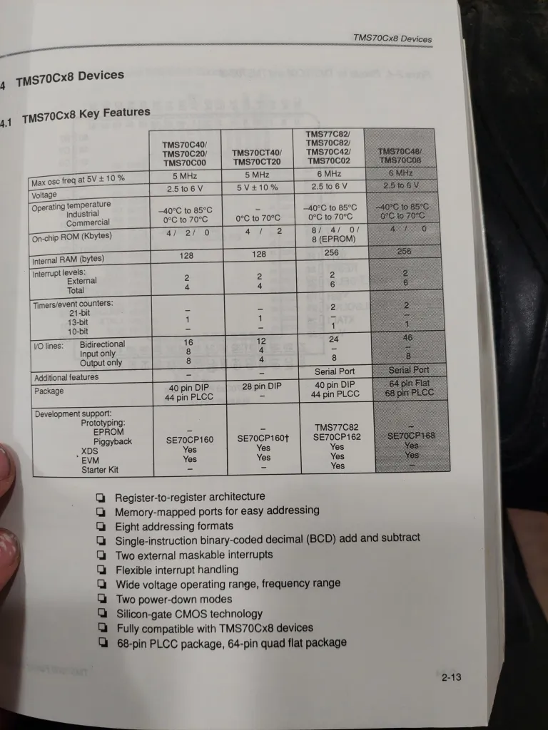
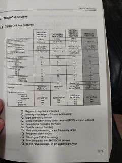
TMS70Cx8 Devices
4.1 TMS70Cx8 Key Features
TMS70C40/TMS70C20/TMS70C00
Max osc freq at 5V ± 10%
5 MHz
Voltage
2.5 to 6 V
Operating temperature
Industrial
Commercial
-40°C to 85°C
0°C to 70°C
TMS70CT40/TMS70CT20
5 MHz
5V ± 10%
128
Internal RAM (bytes)
128
256
256
TMS70C82/TMS70C82
=017b4h ( 6068) load I (137) esp_image: segment 5: paddr=0003ab44 vaddr=50000000 size=00080h ( 128) load I (142) boot: Loaded app from partition at offset 0x10000 I (143) boot: Disabling RNG early entropy source... I (160) cpu_start: Unicore app D (160) cpu_start: Pro cpu up D (168) clk: RTC_SLOW_CLK
/efuse/src/esp_efuse_startup.c:47 I (217) efuse_init: Min chip rev: v0.0 I (220) efuse_init: Max chip rev: v1.99 I (224) efuse_init: Chip rev: v0.1 D (228) cpu_start: calling init function: 0x42003422 on core: 0 --- 0x42003422: __esp_system_init_fn_init_heap at C:/Users/localuser
H2 I H 1 L 0 - 40 0 55 85 125 150 P d Tamb(°C) Note • Zero power is considered as measuring power max. 1 % of max. power. PHYSICAL DIMENSIONS FOR RELEVANT TYPE (all dimensions in millimeters) H1 R25VALUE BMAX. d H2 MAX. L P T MAX. MIN. MAX. 3.3 to 220 5.0 0.6 ± 0.06 1.0 4.0 6.0 24 ± 1.5 2.54 4.0
H2 I H 1 L 0 - 40 0 55 85 125 150 P d Tamb(°C) Note • Zero power is considered as measuring power max. 1 % of max. power. PHYSICAL DIMENSIONS FOR RELEVANT TYPE (all dimensions in millimeters) H1 R25VALUE BMAX. d H2 MAX. L P T MAX. MIN. MAX. 3.3 to 220 5.0 0.6 ± 0.06 1.0 4.0 6.0 24 ± 1.5 2.54 4.0
215˚C 0 8 4 A Electrical Characteristics D The following specifications apply fCC 5 VDC , MIN≤TA≤T MAX and fCLK=640 kHz unless otherwise specified. C 0 Parameter Conditions Min Typ Max Units 0 ADC0801: Total Adjusted Error (Note 8) With Full-Scale Adj. ± 14 LSB 5 (See Section 2.5.2) 1 ADC0802: Total
4bias, 1/8duty, frame frequency is 64Hz ⚫ Max.32×8 patterns, 8 commons, 32 segments ⚫ Built-in internal resistor type bias generator ⚫ 3-wire serial interface ⚫ 8 kinds of time base/WDT selection ⚫ Time base or WDT over flow output ⚫ Built-in LCD
Legende der Display-Symbole Legende der Display-Symbole Wirdangezeigt, wennderMAX- oderMINWert abgerufen wird Zeigt denEmpfangdesRFFunksignalsdesAußensensorsan Wirdangezeigt, wenneinRFFunksignal vomAußensensor gesendet wird Zeigt einenniedrigenBatterieladezustanddesAußensensorsan
Data Memory The internal data memory is divided into four physically distinct blocks: – the lower 128 bytes of RAM including four banks containing eight registers each – the upper 128 byte of RAM – the 128 byte special function register area. – a 2 K 8 area which is accessed like external RAM (MOVX-instructions
Lead–free assembly p P -Temperature Min (T s(min) 150°C Ramp-up Critical Zone TLtoPT Pre Heat -Temperature Max (T s(max) 200°C L tL T -Time (min to max) (s ) 60 – 180 secs es(max) t Average ramp up rate (LiquidusTemp (T )A e Ramp-down 3°C/second max ps(min) to peak e Preheat T T S(max)T A Ramp-up Rate 3°C/second max -Temperature (T ) (Liquidus) 217°C 25˚C Reflow A t 25˚C to Peak -Time (min to max) (t ) 60 – 150 seconds Time (t) s PeakTemperature (T ) 260 +0/°C P Time within 5°C of actual peak 20 – 40 seconds Flow
Drucktasten-Umschaltung S.113/119* Doppelsuper für 10/80 m S. 120/127* Spitzensuper für 10/80 m (Bausatz) S. 128/139* RPB 45/ 46 UKW-Sender- und Empfänger-Baubuch für Amateure, 7. Auflage 70-cm-Empfänger mit Topfkreis S. 95/99 RPB 108 Amateurfunk-Superhets, 2. Auflage 6-Röhren-Kurzwellen-Superhet, 11Bereiche,
Default 1 AT+BAUD Baud rate 9600 2 AT+RFID Wireless ID 8899 3 AT+DVID Device ID 1122 4 AT+RFC Channel(128 Channels) 001 5 AT+POWE Transmit power +10db 6 AT+CLSS Type A0 AT instruction instructions In particular, the JDY-40 module sends the AT instruction need to end the symbol \r\n Setting / query - baud
RC28F128J3A ADP-28F128K3-EBG No Need WA28F V6.15 INTEL EEPROM/FLASH/NVRAM RC28F128J3C ADP-28F128K3-EBG No Need WA28F V6.15 INTEL EEPROM/FLASH/NVRAM RC28F128K3C ADP-28F128K3-EBG No Need WA28F V6.15 INTEL EEPROM
2.26 15043 Support -mrmw option for LAC, LAT, LAS and XCH. 2.25 14058 Internal overflow error on > 128kB flash 2.23 13899 Wrong relaxation of R_AVR_16_PM with gs() 2.23 13697 Wrong symbol values with --gc-sections and empty .data 2.23 13503 Support RELOCs to represent a byte 2.23 13410 Relocation truncated
18037 fixed-point support 4.8.0 53344 Assemble 3-byte symbols 4.8.0 55974 Wrong suffix for __INT24_MAX__, __UINT24_MAX__ with -mint8 4.7.3 55897 Allocate __memx data to .progmemx.data 4.7.3 55243 [ada] STAMP variable is not defined in t-avr 4.7.3 50293 -flto fails if GCC is installed in directory with
assembly T p P -Temperature Min (Ts(min) 150°C Ramp-up Critical Zone TLtoPT Pre Heat -Temperature Max (T s(max) 200°C ) TL L -Time (min to max) (t) 60 – 180 secs ( s rs(max) Average ramp up rate (LiquidusTemp (T ) a A 3°C/second max eT Ramp-down to peak ms(min) t T Preheat T S(max)T A Ramp-up Rate 3°C/second max Reflow -Temperature (TA) (Liquidus) 217°C 25˚C -Time (min to max) (t) 60 – 150 seconds t 25˚C to Peak s Time (t) PeakTemperature (T P) 260+0/-°C Time within 5°C of actual peak 20 – 40 seconds Temperature

 Bild
 Bild
 Bild
 Bild