-
PDF
TJA1020.pdf
note 4 r(slope)(norm)(rec)ormal slope rise time normal slope mode; − 12 22.5 s LIN (0% to 100%) C L 6.8 nF;R L 660 ; V = 12 V; transition BAT from dominant to recessive; note 5 tslope(norm) normal slope symmetry normal slope mode; −4 0 +4 s C L 6.8 nF;R L 660 ; V BAT= 12 V; t − t f(slope)(domr(slope
in „[S] MCP2004 LIN Tranceiver oder andere gesucht“ · Markt ·
-
Bild
Sicherungskasten mit Leitungsschutzschaltern
EATON TEST 230/400V 10000A 0,03A PXL B10/L 5 PXL B16/L 6 PXL B16/L 7 PXL B16/L 8 PXL B16/L 9 PXL B16/L 10 PXL B16/L 11 236776 236029 236033 236033 236033
in „LS löst aus wegen schlechter N-Klemmstelle?“ · Haus & Smart Home · · Fotos
-
Bild
Schaltplan für Anschluss von Ersatzsystemen mit Sunny Island
mit Sunny Island 4.1.1 Umschalteinrichtung für 1-phasiges ES-System Netztrennung Q3 Q2 F2 *1 (40A/0,03A Typ A) F1 *3 X1 L1 L2 L3 N PE SUNNY HOME MANAGER 2.0 *1 optional Phasenkopplung für 1-phasigen Betrieb F3 F4 (C32A) (C32A) Q6 Erdungseinrichtung Q3 Q3 Q4 Q4 Q3 Q3 Q4 Q4 X2 L2 L3 N PE F6 (C32A) F5 *3 Q2 X5 L1 N 1 2 3 4 X3 L1 N PE
in „SMA Sunny Island für "Nulleinspeisung" geeignet?“ · Haus & Smart Home · · Schaltpläne
-
Bild
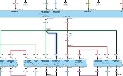
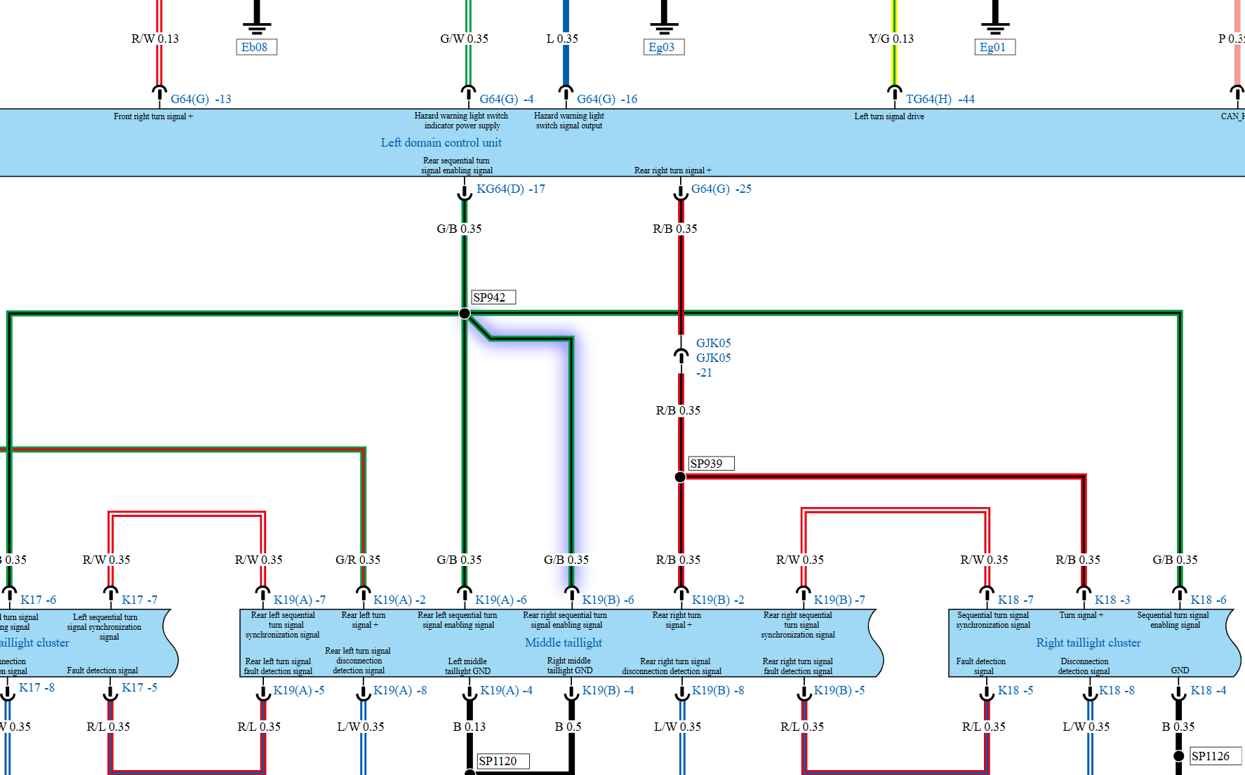
Ausschnitt eines farbigen Schaltplans
R/W 0.13 Eb08 G/W 0.35 L 0.35 Eg03 Y/G 0.13 Eg01 P 0.35 G64(G) -13 Front right turn signal = Hazard warning light switch indicator power supply Left domain control unit Rear right turn signal enabling signal KG64(D) -17 R/B
in „"Defekte Blinker" bei Neufahrzeugen umcodieren?“ · Fahrzeugelektronik · · Schaltpläne
-
PDF
QingKeV2_Processor_Manual.PDF
needs. The following instruction set extensions are supported by QingKe V2 series microprocessors. l RV32: 32-bit architecture, general-purpose register bit width of 32 bits l E: RV32I subset, only 16 general-purpose registers supported l C: Supports 16-bit compression instruction l XW: 16-bit compression
in „CH32V006 und CH32V007 von WCH“ · Mikrocontroller und Digitale Elektronik ·
-
Bild
Dokumente zu Elektronik-Bausatz und Schaltplan
6V, M2 64V, R3 47K, R5 15K, AP8, R2 12K, C9, C10, C13, R10, R15, Tr1, M1, AP7, 90V, DC, R01, R02, R03, C8, C12, C6, 33uF, 33uF, 45V, AP6, L0, L3, L6, L1, L4, L5, R1, R7, R12, R13, R14, R16, C11, C15, AP5, AP4, 25VDC, AP3, KW2, KW1, MW, AP2, AP1, AP0.
in „[V] MW/KW Empfänger Bausätze mit Röhren“ · Markt · · Fotos
-
PDF
Schaltplan__1_.pdf
TX- 1 48 0 O GND TXN AGND +3V3 R3 5.1k▯' USB1 Q1 5 _K1 W5500_TX+ 2 TXP NC 47 A1B12 13 AO3400A W TIM03GR C21 3 46 1k▯' GND R2 GND A4B9 GND EH 8 7 6 5 E +3V3A2 4 AGND NC 45 GND +3V3 L2 +3V3A2 VBUS AVDD PMODE0 5.1k▯' B8 SBU2 W5500_RX- 5 RXN PMODE1 44 +3V3 CBG201209U601T LED1 A5 100nF W5500_RX+ 6 43 GND
in „Platinen Prüfung“ · Platinen ·
-
PDF
Grille_prix_Tarif_Bleu.pdf
Grille de prix de l’offre de fourniture d’électricité « Tarif Bleu » er Applicable au 1 février 2026 OFFRE POUR LES CLIENTS PARTICULIERS L’offre « Tarif Bleu » porte sur la fourniture d’électricité et sur l’accès et l’utilisation
-
PDF
t1610.pdf
Relative variation of gate trigger current sinusoidal I , I , I [Tj] / I , I , I [T = 25 °C] GT H L GT H L j 2.5 I (A),I t (A s) holding current and latching current versus junction TSM temperature (typical values) 3000 Tjinitial=25°C 2.0 dI/50A/µsitation: GT 1.5 1000 TSM IH& L 1.0 0.5 T(j°C) 0.0 pulse
-
PDF
Elektronusches_Uhren_Relay-V4.pdf
~ ~ 11 W ~ B /~lL 1I R3 11 700 11 FZHZ!,I rc s ~~~ 71FZH21,1 IOD I, 6 I. ~Qf ulf 18 8 69l.~ 614l~ t R25 11.l5)1F c 47072 .D _ ~lf TlJ 9 ~ ~ 4 ZIRI3 7 ~ Tll I R5 _V I 8 -./:'".l R6 F ~ 67 ~[4: +1)1F 330,1.2k ,"-' 3JO.lZh
in „Polwechselnden Impuls mit Transistoren verstärken“ · Analoge Elektronik und Schaltungstechnik ·
-
Datei
Disassemblyjbt3.a51
Address_F25 ;BD02CD -- '' ljmp Address_DD02 ;02DD02 -- '' mov a,r5 ;ED -- '' Address_F5C: ljmp Address_FD03 ;02FD03 -- '' rrc a ;13 -- '' rr a ;03 -- '' rl a ;23 -- '#' rr a ;03 -- '' addc a,r3 ;3B -- ';' rr a ;03 -- '' orl a,r4 ;4C -- 'L' rr a ;03 -- '' anl a,r6 ;5E -- '^' rr a ;03 -- '' DB 0x71 ;71 -- 'q' Address_F6A: DB 0x03 ;03 -- '' anl c,Bit_03 ;8203 -- '' movc a,@a+dptr ;93 -- '' rr a ;03 -- '' mov @r0,Register_03 ;A603 -- '' cjne r2,#0x03,Address_F3E ;BA03CA -- '' rr a ;03 -- '' djnz r3,Address_F7A ;DB03 -- '' Address_F77
in „Eprom von Denon DJ Laufwerk defekt Winbond 78e52“ · Mikrocontroller und Digitale Elektronik ·
-
PDF
asus-p701-unlocked.pdf
1 5 4 3 2 1 CIRCUIT UPDATED HISTORY Rev Date Description Rev Date Description 1.0G 2007/02/26 S701L Schematic 1.0G Beginning 1.2G 2007/06/30 P701 Schematic 1.2G Beginning ~ ~ ~ ~ 1. Add R174 to short DASP pins of Master IDE device and SLave IDE device D 2007/03/16 S701L 1.0G Gerber Out 2. Use SB GPIO27
-
Bild
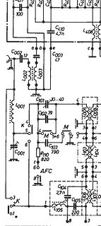
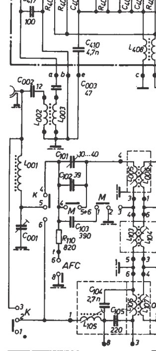
Ausschnitt eines Schaltplans
R4, C4, R4, C4, C410, 4,7n, L408, c, a, b, e, C003, 47, L2002, L003, C101, 10...40, 4, C102, 39, M, 5+6, M, 1, 2, 3, 4, 6, C103, 390, R110, 820, 5, 6, AFC, 1, 60, 8, C104, 2,7n, C105, 220, L105, 1, 3, 8, 03, 02, K, 01
in „Interpretation veränderlicher Widerstand im Antenneneingangskreis“ · HF, Funk und Felder · · Schaltpläne
-
PDF
MWE_RSD-30-SERIE_DB-EN.pdf
RSD-30L-3.3 RSD-30L-5 RSD-30L-12 RSD-30L-24 DCVOLTAGE 3.3V 5V 12V 24V 3.3V 5V 12V 24V RATEDCURRENT 6A 6A 2.5A 1.25A 6A 6A 2.5A 1.25A CURRENTRANGE 0~6A 0~6A 0~2.5A 0~1.25A 0~6A 0~6A 0~2.5A 0~1.25A RATEDPOWER
in „Kindereisenbahn hohe Stromspitzen begrenzen“ · Fahrzeugelektronik ·
-
Bild
GE Kondensator mit Anschlüssen
GE CAPACITOR DANGER HIGH VOLTAGE 23L6562R 1. 14uf 2100 VAC +03 -03% b 50/60Hz T85C 7463M002 DIELEKTROL III 97300 983 101N100 No PCB's Assembled in Mexico
in „Mikrowelle reparieren?“ · Analoge Elektronik und Schaltungstechnik · · Fotos
-
Thread
ESP32-E22 offiziell, neuer Mikrocontroller von WCH, Raspberry Pi-Tethering uvam
and deep sleep that bring them closer to first-class status. New hardware support includes the RD-03D mmWave radar and BTHome v2 parsing for Xiaomi sensors, while Zigbee on nRF52 expands with sensor, binary sensor, and switch support. [/c] ### NXP UCODE X – RFID-Tag mit hoher Reichweite NXP lanciert
Zitat Udo L.: >> Wenn Krieg so geil ist wie im Kino, lass doch endlich starten <<
Mikrocontroller und Digitale Elektronik ·Tam H. · ·23 Antworten
-
PDF
DOC004015493.pdf
for RPT(G)-160-C )60 D 38 ( A A50 L O 20 L40 -20 0 10 20 30 40 50 60 70 (HORIZONTAL) 90 95 100 115 120 140 160 180 200 220 240 264 AMBIENT TEMPERATURE (℃) INPUT VOLTAGE (VAC) 60Hz File Name:RPT-160-SPEC 2018-01-12 145W Reliable Triple
in „Willtek Schlumberger Stabilock 4031 4032“ · HF, Funk und Felder ·
-
PDF
DOC004015493.pdf
for RPT(G)-160-C )60 D 38 ( A A50 L O 20 L40 -20 0 10 20 30 40 50 60 70 (HORIZONTAL) 90 95 100 115 120 140 160 180 200 220 240 264 AMBIENT TEMPERATURE (℃) INPUT VOLTAGE (VAC) 60Hz File Name:RPT-160-SPEC 2018-01-12 145W Reliable Triple
in „Willtek Schlumberger Stabilock 4031 4032“ · HF, Funk und Felder ·
-
Datei
CoolTerm_Capture__FritzAVM_1V8.CoolTermSettings__2026-06-27_08-52-21-633.txt
À°r"ÀU@ ÿÿ ýÿ `ðm" ²X ÿÀÅÎ P ððy" ²X ÿÀ±Î P ²X ÿÀ¥Î P ²X ÿÀ Î P À[° P `pm" p2$p ýÀ õýÀËð 02$/¿ þÀ; 03$ 0p"è þÀ 03$ýÀññ ¿þ P /à °°P °P °P °P ã à À²!@P O ¿þ P ?s ã ? ¿ ð ] _ è| x$œX@ ° P ¿ú P YýÀÏõW¿û Q] _!L U L1aÃU a š a ° QC Yâ 0 ð ¿ ÁPI YRY ÀŸ)ä ÄU ¿û L U L a aBU š aÒð@U/±ò "]"_ aÐð p3$ € ` ï. ¢ ` ï
in „FRITZ!Box 7490 Bootloop“ · Mikrocontroller und Digitale Elektronik ·
-
PDF
grip1.pdf
X) W EI 15-, O 7 a: Q) D C/} 'M o iH o O N O XI k 1 •P EH r f \ s x: (1) CO l-l ^ •H W o (H C •H E IM üG Ncu 01 rn> ,_, O •sT E (U C •o |T 1-1 N p •i -0) C ,—1 0 In •a cd ^S -p i-i OH 03 C/} •r-l t" •a (H E) e c cD 0 cu _ ^, Mu g CONIT J. H Christian LotterDatensysteme r - i £
in „Conitec PROF-80 Informationsseite“ · Mikrocontroller und Digitale Elektronik ·
-
Bild
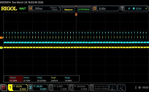
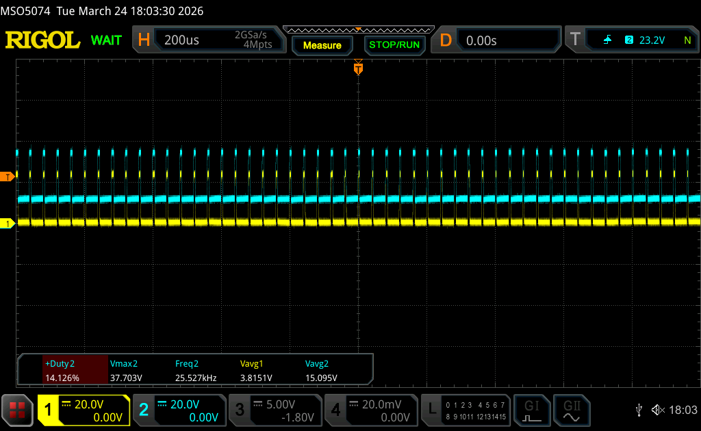
Oszilloskop-Messung zweier periodischer Signale
MSO5074 Tue March 24 18:03:30 2026 RIGOL WAIT H 200us 2GSa/s 4Mpts Measure STOP/RUN D 0.00s T 2 23.2V N +Duty 2 Vmax2 Freq2 Vavg1 Vavg2 14.126% 37.703V 25.527kHz 3.8151V 15.095V 1 20.0V 2 20.0V 3 5.00V 4 20.0mV 0.00V 0.00V -1.80V 0.00V L GI GII 8 9 10 11 12 13 14 15 18:03
in „DRV8162 mit Trickle Charge Pump“ · Analoge Elektronik und Schaltungstechnik · · Oszi-Bilder
-
Bild
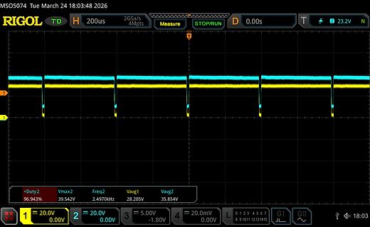
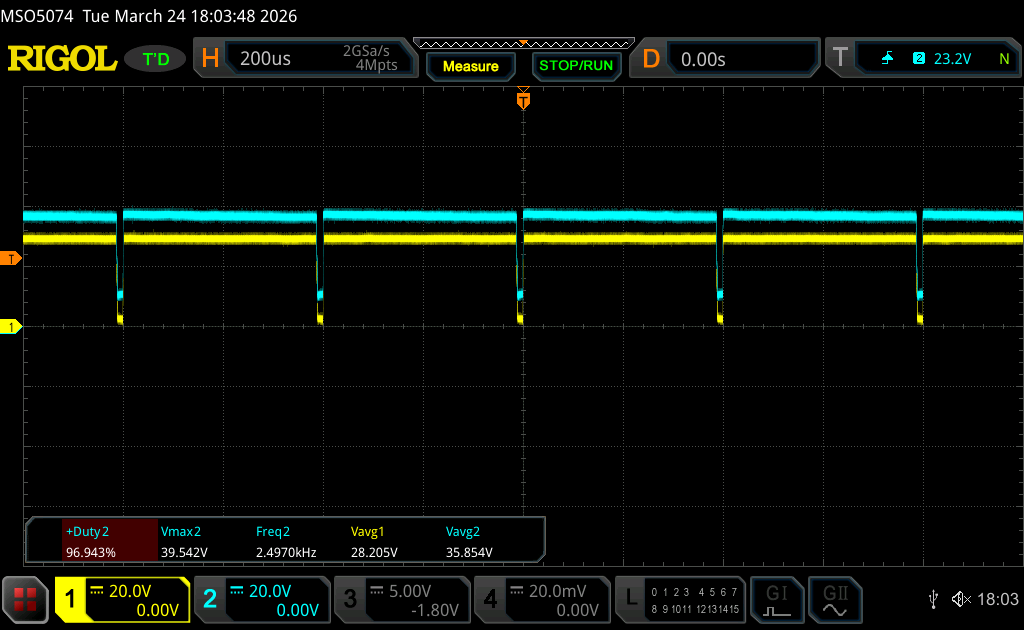
Oszilloskop-Messung eines Rechtecksignals
MSO5074 Tue March 24 18:03:48 2026 RIGOL T'D H 200us 2GSa/s 4Mpts Measure STOP/RUN D 0.00s T 2 23.2V N +Duty 2 96.943% Vmax2 39.542V Freq2 2.4970kHz Vavg1 28.205V Vavg2 35.854V 1 20.0V 0.00V 2 20.0V 0.00V 3 5.00V -1.80V 4 20.0mV 0.00V L GI GII 8 9 10 11 12 13 14 15 18:03
in „DRV8162 mit Trickle Charge Pump“ · Analoge Elektronik und Schaltungstechnik · · Oszi-Bilder
-
PDF
SHUTTLE_SPCEL02_DB-DE.pdf
Eingänge und Mount & Netzteil ist Demnächst 2x 2.5G LAN 4x Ausgänge DIN-Rail nicht enthalten SPCEL03 Intel Atom x6413E 887993007229 — -20 … 60 °C 2) (4-Kerne, 1,5-3,0 GHz, 9 W) SPCEL12 Intel Celeron J6412 2x HDMI 2.0, 1xDP 2.5G LAN, 2x Audio VESA 12-20 V DC 887993007243 — 0 … 40 °C (4-Kerne, 2,0-2,6
in „[V] Shuttle SPCEL02“ · Markt ·
-
Datei
oled_demo.c
// Ascii 90 = 'Z' { 0x00, 0x00, 0x7f, 0x7f, 0x41, 0x41, 0x00, 0x00 }, // Ascii 91 = '[' { 0x01, 0x03, 0x06, 0x0c, 0x18, 0x30, 0x60, 0x00 }, // Ascii 92 = '\' { 0x00, 0x00, 0x41, 0x41, 0x7f, 0x7f, 0x00, 0x00 }, // Ascii 93 = ']' { 0x00, 0x08, 0x0c, 0x06, 0x03, 0x06, 0x0c, 0x08 }, // Ascii 94 = '^' { 0x80, 0x80, 0x80, 0x80, 0x80, 0x80, 0x80, 0x80 }, // Ascii 95 = '_' { 0x00, 0x00, 0x01, 0x03, 0x06, 0x04, 0x00, 0x00 }, // Ascii 96 = '`' { 0x20, 0x74, 0x54, 0x54, 0x54, 0x7c, 0x78, 0x00 }, // Ascii 97 = 'a' { 0x7f, 0x7f, 0x44, 0x44, 0x44, 0x7c, 0x38, 0x00 }, // Ascii 98 = 'b' { 0x38, 0x7c,
in „I2C Display einfache Frage“ · Mikrocontroller und Digitale Elektronik ·
-
Datei
oled_2313demo.c
// Ascii 90 = 'Z' { 0x00, 0x00, 0x7f, 0x7f, 0x41, 0x41, 0x00, 0x00 }, // Ascii 91 = '[' { 0x01, 0x03, 0x06, 0x0c, 0x18, 0x30, 0x60, 0x00 }, // Ascii 92 = '\' { 0x00, 0x00, 0x41, 0x41, 0x7f, 0x7f, 0x00, 0x00 }, // Ascii 93 = ']' { 0x00, 0x08, 0x0c, 0x06, 0x03, 0x06, 0x0c, 0x08 }, // Ascii 94 = '^' { 0x80, 0x80, 0x80, 0x80, 0x80, 0x80, 0x80, 0x80 }, // Ascii 95 = '_' { 0x00, 0x00, 0x01, 0x03, 0x06, 0x04, 0x00, 0x00 }, // Ascii 96 = '`' { 0x20, 0x74, 0x54, 0x54, 0x54, 0x7c, 0x78, 0x00 }, // Ascii 97 = 'a' { 0x7f, 0x7f, 0x44, 0x44, 0x44, 0x7c, 0x38, 0x00 }, // Ascii 98 = 'b' { 0x38, 0x7c,
in „I2C Display einfache Frage“ · Mikrocontroller und Digitale Elektronik ·
-
Bild
Software zur Auslegung eines Inverting Buck-Boost Wandlers
Cycle: 8.68 % On-Time: 0.17 µs Off-Time: 1.83 µs Zero-Time: 0.00 µs RHPZ: 222.54 kHz Load Current: -0.03 A Input Power: 0.05 W Output Power: 0.03 W Diode Losses: 0.02 W Input Current: 0.00 A Current Ripple: 0.01 A 38.42 % Q1, D1, Ci, L1, Co
in „Wie im Bereich von 1,2Vdc - 117Vdc einstellbare Konstantspannung aus 20Vdc erzeugen?“ · Mikrocontroller und Digitale Elektronik · · Screenshots
-
PDF
Schematic_ESP32-MES-WiFi_2026-03-31.pdf
Sheet: 1/1 Date: 2019-05-15 Drawn By: g3gg0.de 1 2 3 4 5 1 2 3 4 5 T VCC ESP32 _ WS2812 P 2 1 U4 M L L ESP32-WROOM/WROVER T R R I E O D D R 1 2 A R7 N N N 2 1 A 1k O O O S 2 23 16 L L L W S 24O15 I153 W 25O2 G14 VCC5 IO0 26O0 I132 LED5 WDT_WDI 27O4 I124 STATUS 28C I117 DI GND 29C I106 30O5 I925 WS2812
in „LON Bus Windhager mitlesen/steuern“ · Haus & Smart Home ·
-
Bild
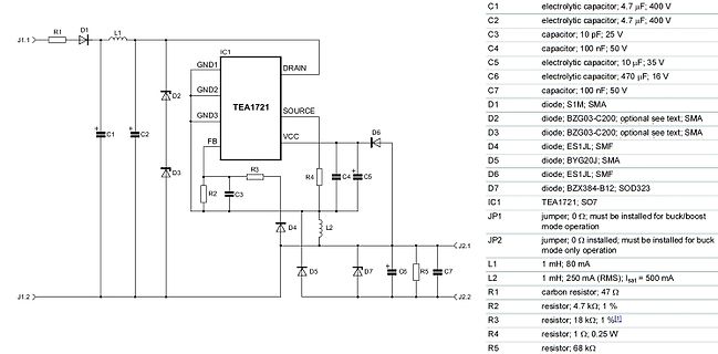
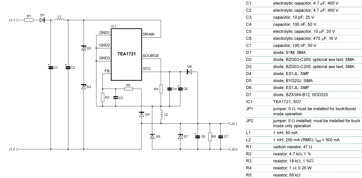
Schaltplan eines TEA1721-basierten Netzteils
J1.1 R1 D1 L1 C1 C2 GND1 GND2 GND3 IC1 TEA1721 D2 FB SOURCE VCC D6 D3 R3 R2 C3 R4 D4 L2 SO7 JP2 JP1 D5 D7 C4 C5 C6 R5 C7 J1.2 J2.2 C1 electrolytic capacitor; 4.7 uF; 400V C2 electrolytic capacitor; 4.7 uF; 400V C3
in „Ersatz SMD Diode ON VP30“ · Analoge Elektronik und Schaltungstechnik · · Schaltpläne
-
Bild
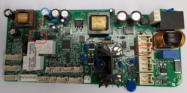
Bestückte Leiterplatte eines Netzteils
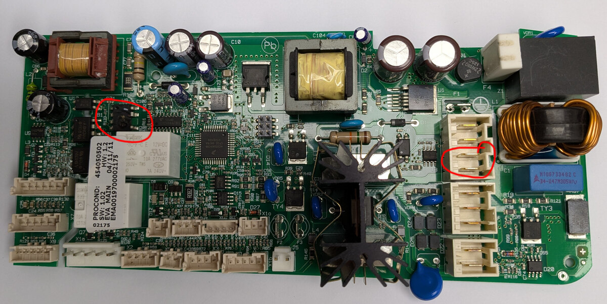
C10, C104, VDR1, US, 48405050, 04/11, EVA MAIN, 18A 274AC, 7A 242V, SW: 1.02, EVA MAIN, 03/07/2007, 02175, X15, X16, X17, X18, L1, L2, TY3, D20, N1097324 02, X4-L47H305V
in „Brauche Unterstützung bei der Reparatur eines Gaggenau Vollautomaten CM250100/06“ · Analoge Elektronik und Schaltungstechnik · · Platinenfotos
-
PDF
LM317.PDF
Pulse testing required. Adjust *▯1% Duty Cycle R1 240 + *▯is suggested. C 0.1 F IAdj 1% C 1.0 F R in O L R2 1% Figure 1. Line Regulation and I Adj/Line Test Circuit http://onsemi.com 3 LM317 VI Vin Vout LM317 IL VO(min Load) RL V (max Load) (max Load) O Adjust 240 R R1 1% * L + (min Load) C in 0.1 F Adj
in „Spannungsregler für Kleinverbraucher bei 1,2V gesucht“ · Analoge Elektronik und Schaltungstechnik ·
-
Bild
Schaltplan mit Rotary Encoder und DMX-Schnittstellen
_01x03, TERM_12V_OUT, R_TERM_TOP1 47k, R_TERM_BOT1 15k, TERM_ACTIVE, +3V3_LOGIC, D_TERM_CLAMP1, D_Schottky, TestPoint, R_TERM_IN1 390R, LED_DMX_IN1, LED, C_TERM_LVL1 100nF, TP_TERM_ACTIVE1, DMX_IN_5V_ISO, U_TERM_IN1, ACPL-M61L, 1, 2, 3, 4, C_TERM_IN1, DMX_IN_GND_ISO, J_DLED1, Conn_01x04, A, NC, 2, 5, GND, VDD, GND, VO, R_PU_TERM_IN1 10kΩ, GND
in „Artnet-DMX-Node mit 2× DMX Out + 1× DMX In, komplett galvanisch getrennt - gibt es ähnliche Projekte“ · Mikrocontroller und Digitale Elektronik · · Schaltpläne
-
Bild
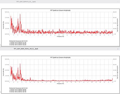
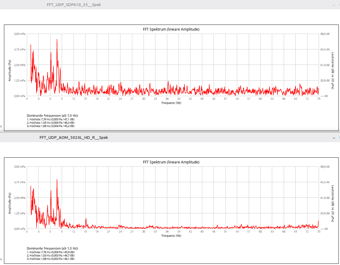
Zwei FFT-Spektrum-Diagramme der Amplituden
66 69 72 75 Dominante frequenzen (ab 1,0 Hz): 1. Höchste 7,76 Hz (0,005 Pa / 47,1 dB) 2. Höchste 1,03 Hz (0,004 Pa / 46,3 dB) 3. Höchste 1,68 Hz (0,004 Pa / 45,2 dB) FFT_UDP_AOM_5024L_HD_R_Spek FFT Spektrum (lineare Amplitude) Amplitude (Pa) Leistung (dB in 20 µPa) 0,00 mPa 1,25 mPa 2,50 mPa 3,75 mPa
in „Dumpfer Lärm Logger bauen“ · Digitale Signalverarbeitung / DSP / Machine Learning · · Screenshots
-
Bild
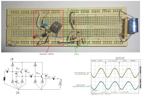
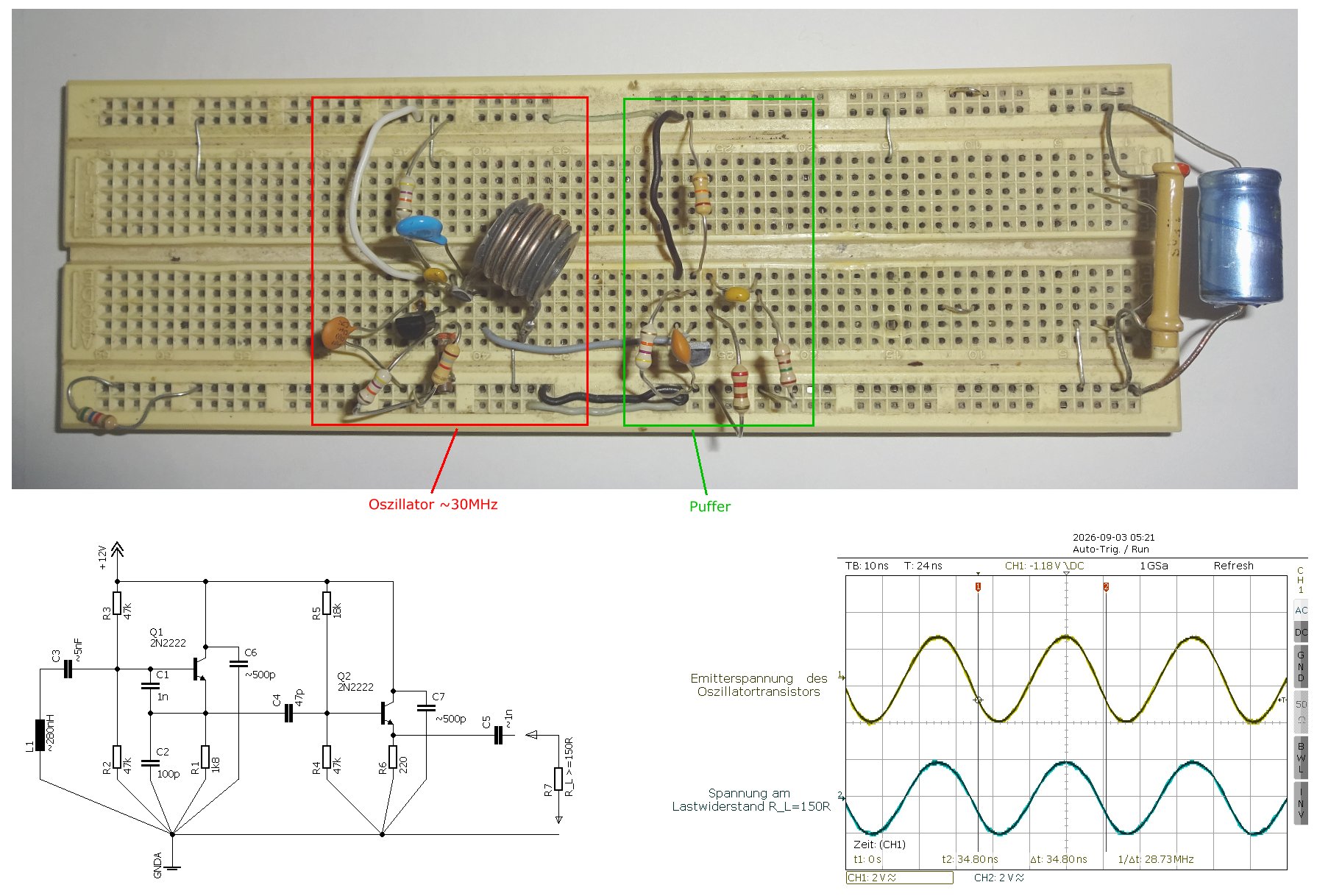
Breadboard-Aufbau, Schaltplan und Oszilloskop-Messung eines Oszillators
C3, 5nF, C1, 1n, Q1, 2N2, C5, ~50p, Q2, 2N2, C4, 47p, R5, 10k, C7, ~50p, R4, 47k, C6, 220, R2, 10p, L1, ~280HM, R1, 150R, R_L, 150R, 2026-09-03 09:21, Auto Trig./Run, TB: 10 ns T: 24 ns, CH1: -1.18V DC, 1GSa, Refresh, CH1, AC, 50 mV, Spannung am Lastwiderstand R_L=150R, CH1: 2 V/s, Zeit: 1 0s, 12: 34.80
in „Colpitts-Oszillator in Kollektorschaltung“ · HF, Funk und Felder · · Fotos
-
Bild
Schaltplan eines ESP32-H2 Mikrocontrollers
to be 24 nH. GND, C1, C4, Y1, XIN, XOUT, TBD, VDD33, C2, 10nF, 50 ohm Impedance Control, ANT1, C3, L1, C11, L2, C12, LNA IN, R4, C10, 0.1uF, C5, 1uF, GPIO27, GPIO26, GND, ANT, VDD3P3, GPIO22, U0RXD, U0TXD, GPIO25, R3, 499, VDD3P3, GPIO00, GPIO01, GPIO02, GPIO03, MTDO, MTCK, MTDI, XTAL_P, XTAL_N, CHIP_EN
in „Womit Stromverbrauch (µA..mA) in Graphen darstellen?“ · Mikrocontroller und Digitale Elektronik · · Schaltpläne
-
Datei
event_ctrl.ino
------------------------ event_ctrl.ino Eventbasierendes System, hier ganz bewusst ohne Interrupts 03.05.2026 R. Seelig -------------------------------------------------------- */ #include "sn74hc595.h" /* ---------------------------------------------------------------------- Objektinstanz von shiftreg595
in „Schulnotenbewertung eines Arduino-Programms“ · Mikrocontroller und Digitale Elektronik ·
-
Datei
event_ctrl.ino
------------------------ event_ctrl.ino Eventbasierendes System, hier ganz bewusst ohne Interrupts 03.05.2026 R. Seelig -------------------------------------------------------- */ #include "sn74hc595.h" /* ---------------------------------------------------------------------- Objektinstanz von shiftreg595
in „Schulnotenbewertung eines Arduino-Programms“ · Mikrocontroller und Digitale Elektronik ·
-
PDF
ESP32-H2-Zero-Schematic.pdf
PIC602 PI1601 USB_P GPIO_P PIP101 GPIO8 PIP201 2 0 4 GND Testpoint Testpoint GND Y1Y10P32MHz P3P P4P 3 L1L 24nH GND USB_N GPIO_N GPIO9 J2J C7CC7P14pF1PIL102 GNDL101 P I Testpoint P I PTestpoint 贴片天线 CA-C03 PIJ20COR 82O8 I2 C9C 21 PIR40PIR401_2G4 02 81uF I1100nF P0 C11 0 C1C2 10nF P2 7.5nH 0 1.5pF 0 GPIO_N 2 V V P NV N T P P A AP GND G A E E X X E C 0 P U301239P8I7U605 COU C GND ESP32-H2FH4S N N 3 3 L L3 O O G A D D T TD P P 32 I2 52 V V X XV G G C131 O14 O15 300uF I0uF 5000nFESP_3V3 PIU20VDD3P3 GPIO25PIU2024GPIO25 3V3 3V3 ESP_3V3 PIU20VDD3P3 U0TXD PIU2023 49PIR50PIR502RT_TXD VCC_5V GPIO1 PI420GPIO0
in „ESP32-C6 an 18650 Akku betreiben“ · Mikrocontroller und Digitale Elektronik ·
-
Bild
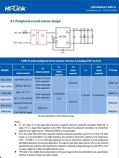
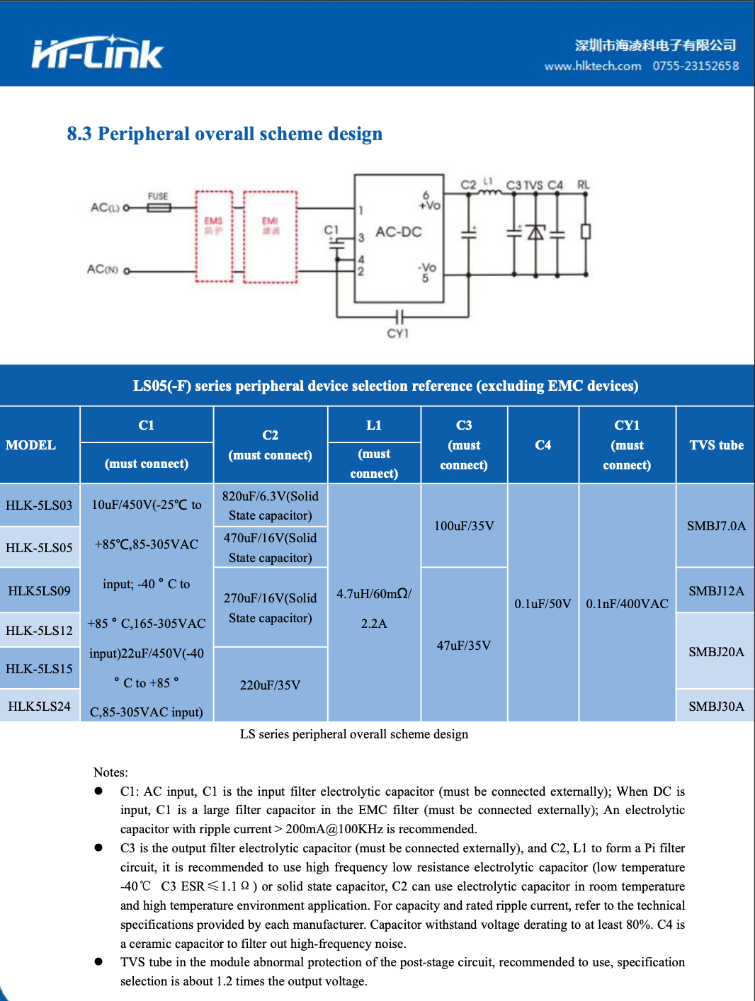
Schaltplan und Bauteiltabelle eines AC-DC-Wandlers
Hi-Link 深深圳市海派电子有限公司 www.hlktech.com 0755-23152658 8.3 Peripheral overall scheme design AC(L) FUSE EMS C1 C2 L1 C3 C4 RL AC-DC +Vo -Vo LS05(-F) series peripheral device selection reference (excluding EMC devices) MODEL C1 C2 L1 C3 C4 CY1 TVS tube HLK-5LS03 10uF/450V(-25°C to +85°C,35-305VAC)
in „28,5 V 4W aus 230V AC - HLK5LS24“ · Analoge Elektronik und Schaltungstechnik · · Screenshots
-
Bild
Nahaufnahme einer roten Leiterplatte mit elektronischen Bauteilen
R354, V300, L304, L305, U303, TP219, TP218, C248, TP221, R503, R501, R502, C504, L502, 1R5, 4P03.04, R505, C505, R504, R502, R503, C506, Q501, R507, Q506, Q507, R505, TP218, C503, C502, C501, R501, R500, R501, R502
in „Hilfe bei Bauteilidentifikation- Teufel Rockster Air“ · Analoge Elektronik und Schaltungstechnik · · Platinenfotos
-
PDF
6ff78f.pdf
R R R R 0 m m R C 1 3 1 3 2 2 7 7 7 7 2 K b e U V V 1 3 1 3 4 3 2 1 R R R C C r r T O P A 0 3 R A 03 R V V V V V V 2 2 2 R 1 D , O U W 7 3 U K0 2 0 R R RR 1 R R R V 9 8 7 2 , A T W X 6 X W 9 U W 8 7 62 U K 5 4 3 3 6 1 3 0 G D E A B X 5 X W 2 2 A R R R V 0 R . R E E A B N 1 0 9 3 3 M W E E E E 5 8 L
in „Mischpult "Alesis Multimix 8" (Knallen auf allen Ausgängen)“ · Analoge Elektronik und Schaltungstechnik ·
-
Thread
Thinkpad T 220 und 420: ultrarobust - gesucht: würdiger & ähnl. unverwüstlicher Nachfolger
Selbst auf der Arbeit hat der L15 ewig gehalten und wir waren regelmäßig im Feld damit unterwegs. Etwas schwacher auf der Brust aber es hat immer gereicht.
sogar mit einer kleineren SSD > aus. Danke schön Wolf17 - leuchtet ein! von Ein T. (ein_typ)03.08 >> Was meint ihr also, sollte ich hier tun!? > > Da kann ich nur wiederholen, was ich oben bereits geschrieben hatte: bau > mehr Arbeitsspeicher ein, idealerweise bis zu den für die CPU möglichen
PC Hard- und Software ·To G. · ·53 Antworten
-
PDF
191142-03.pdf
www.elektormagazine.deJanuar/Februar 202063 Walter Valentin - 15513 B4 B1 KBPC3510 DB107 F1 6A Tr1 MGND K4 K2 S1 C1 1 L 12V 470µ S 2 (N) L P 50V P 3 N O (N) S2 RE1 12 V B2 2 1 DB107 D1 C2 T1 470µ 1N4007 BC547 50V MGND R1 VR1 C4 B3 3W IC1 V25S275P 220n DB107 4 1 PC817X4J000F R6 630V R2 4 5W 1 3 5 k 560 1 K1 2 3 2 4 6 +
in „Einstellbarer 1-kW-AC-Motortreiber“ · Mikrocontroller und Digitale Elektronik ·
-
PDF
T-3.pdf
D307,D319,D320,DSWITCHING DIODE(1SS132/1SS133,300mw,55V,T-77) 414-3113-005 12 21,D322,D323,D324,D 325 L307,L302,L303,L30BEAD CORE(86-019-A TAPING) 415-HV3500K-090 6 L305,L306 L301 INDUCTOR(10uH TAPING 52mm) 415-MPG100-047 1 IC303 IC ASS'Y(CHECK SUM:B03A/1) 704-3000-4857 1 IC(W78E52C-40,DIP-40) 417-HV3288K
in „Eprom von Denon DJ Laufwerk defekt Winbond 78e52“ · Mikrocontroller und Digitale Elektronik ·
-
Datei
t13-charlieplexing.asm
Fotodiode A o--|PB4 PB1|--o 470R -- LEDKette-Pin2 ; Fotodiode K o--|GND PB0|--o 470R -- LEDKette-Pin3 ; L_________/ ; ; ; ********************************** ; P O R T S A N D P I N S ; ********************************** ; ; (Add symbols for all ports and port pins with ".equ" here) ; (e.g. .equ pDirD = DDRB
in „Attiny13a stürzt ab“ · Mikrocontroller und Digitale Elektronik ·
-
Datei
t13-charlieplexing.asm
Fotodiode A o--|PB4 PB1|--o 470R -- LEDKette-Pin2 ; Fotodiode K o--|GND PB0|--o 470R -- LEDKette-Pin3 ; L_________/ ; ; ; ********************************** ; P O R T S A N D P I N S ; ********************************** ; ; (Add symbols for all ports and port pins with ".equ" here) ; (e.g. .equ pDirD = DDRB
in „Attiny13a stürzt ab“ · Mikrocontroller und Digitale Elektronik ·
-
Bild
Nahaufnahme einer beschädigten Leiterplatte mit Elektrolytkondensatoren
Teufel QC PASS QC 03 220 2C23 2C28 2L06 2C20 2R14 2C19 2R13 2C18 2L05 E257130 94V-0 BC-2 10 8521 40 2) 2C33 2C29
in „Teufel US 2110/1 SW - Kondensator Kapazität gesucht“ · Analoge Elektronik und Schaltungstechnik · · Platinenfotos
-
Bild
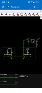
Schaltplan in Falstad Simulator
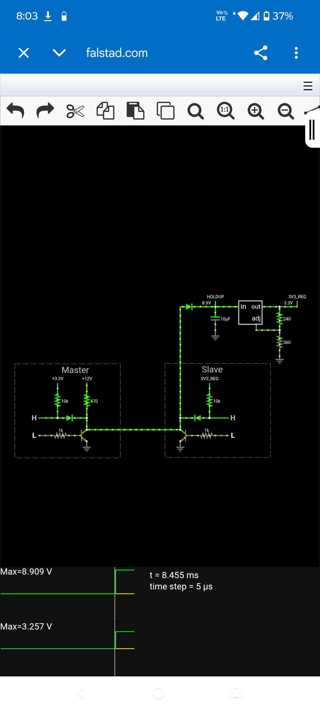
falstad.com 8:03 37% HOLDUP 8.9V 3V3_REG 3.3V in out adj 240 360 Master +3.3V +12V 10k 470 H L Slave 3V3_REG 10k H L Max=8.909 V t = 8.455 ms time step = 5 µs Max=3.257 V
in „Can two Arduino Unos talk over a 2-wire M-Bus style bus (9V/7V + current reply) across 50 Meters“ · Mikrocontroller und Digitale Elektronik · · Screenshots
-
Bild
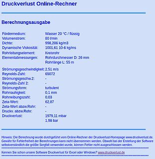
Ergebnis einer Druckverlust-Berechnung
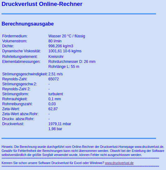
Druckverlust Online-Rechner Berechnungsausgabe Fördermedium: Wasser 20 °C / flüssig Volumenstrom: 80 l/min Dichte: 998,206 kg/m3 Dynamische Viskosität: 1001,61 10-6 kg/ms Rohrleitungselement: Kreisrohr Elementabmessungen: Rohrdurchmesser D: 26 mm Rohrlänge L: 55 m Strömungsgeschwindigkeit: 2,51 m/s Reynolds-Zahl: 65072 Strömungsform: turbulent Rohrrauigkeit: 0,1 mm Rohrreibungszahl: 0,03 Zeta-Wert: 62,87 Druck. abzw.Rohr: Druckverlust: 1,98 bar
in „Leistungsaufnahme bei Brunnenpumpe“ · Haus & Smart Home · · Screenshots
-
Bild
Foto eines Windows Task-Managers auf einem Bildschirm
1,81 GHz Basisgeschwindigkeit 1,44 GHz Prozesse 155 Threads 1772 Handles 60516 Logische Prozessoren 4 L1-Cache 224 KB L2-Cache 2,0 MB 13.03.2026
in „[V] W10 4GB/64GB Minirechner _LATTE_PANDA(Onboard .ATmeg32) 88*70mm 5V LAN,HDMI,USB (30€)“ · Markt · · Fotos
-
PDF
RS-25-SPEC.pdf
Switching Power Supply RS-25 series Mechanical Specification Case No.931A Unit:mm 1 . 7 2 3 1 5 6 4 2-M3 L=3 . 5 2 LED +VADJ. 55 10.5 78 14 max. Terminal Pin No. Assignment 2 Pin No. Assignment Pin No. Assignment 1 AC/L 4 DC OUTPUT -V 2-M3 4 2 AC/N 5 DC OUTPUT +V 1 3 FG 66.5 2.75 Block Diagram fosc : 60KHz EMI RECTIFIERS POWER RECTIFIERS +V I/P & & FILTER FILTER SWITCHING FILTER -V FG PWM DETECTION O.L.P. CONTROL CIRCUIT Derating Curve Output Derating VS Input Voltage 100 Others 100 90 80 80 3.3V only 60 70 % ) 60 ( 40 ( A D O O 50 L 20 L 40 -20 0 10 20 30 40 50 60 70 (HORIZONTAL) 88 95 100 115 120
in „Willtek Schlumberger Stabilock 4031 4032“ · HF, Funk und Felder ·