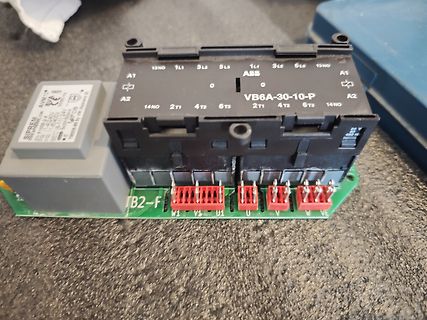
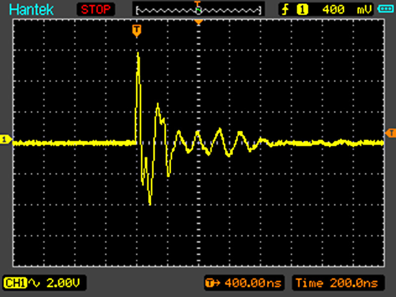
Moin, Ich habe hier ein älteres Oszilloskop Phillips P400, baugleich Metrix OX803, wurde wohl auch mal unter Voltcraft vertrieben. Als ich es nach Längerem wieder in Betrieb genommen habe, war kurz ein Punkt auf dem Schirm, dann schnell verschwunden. Kein
Andrew T. schrieb im Beitrag #8057904: > Tipp der Dir die Arbeit erleichtert: cut¬paste (Kopiere Textteile und > setz es in deepl.com, führt zu einer recht brauchbaren übersetzung ins > Deutsche) Der übersetzt
noted) Parameter Symbol Limit Unit Collector-Base Voltage VCBO 700V V Collector-Emitter Voltage VCEO 400V V Emitter-Base Voltage VEBO 9 V DC 1.5 Collector Current IC A Pulse 3 o TO-92 1.5 Total Power Dissipation @ Tc= 25 C Ptot W TO-126 30 Operating Junction Temperature T +150 oC J Operating Junction and
0.4 A R .4 O E W E F R 0.2 R P S E 0.1 F M .2 U P 0.06 E A O A 0.04 G E 0.02 A 0 N R 0 50 100 150175 T 0.00.6 01.0 1.1.4 1.62.08 E N A A T AMBIENTTEMPERATURE, N INSTANTANEOUSFORWARDVOLTAGE,VOLTS I FIG.4--PEAKFORWARDSURGECURRENT FIG.5---TYPICALJUNCTIONCAPACITANCE T N 25 E F 10 R , R 20 E 16 U C 14 C N E 15 T 12 G T =125 I U S 8.3ms Single Half A 10 S R Sine-Wave P D E 10 A R P C 4 TJ=25 A M N f=1MHz W A 5 I 2 R T O C 1 F 0 N .1.2 .4 1.0 24 10 2040 100 K 1 2 4 1 0 2 0 40 100 J E P NUMBEROFCYCLESAT60Hz REVERSEVOLTAGE
-7 6.3 V 1% R4 68 Ω 600 V 2.2 nF 1/16 W 1.8 MΩ 5 50 V 1% 4 NC Q1 AO6420 F1 C2 C3 3 1 A 10 µF 10 µF T1 R13 400 V 400 V EE1621 331% kΩ RT1 tO 47 Ω 1/16 W 10 Ω 1/10 W C12 225 VF C7 90 - 265 DFLR1200-7 2.2 µF C8 VAC VR1 25 V 330 pF L N MMSZ5231B-7-F 50 V D S N D3 D V F S V B G BAV21WS-7-F CONTROL R12 R26
in housing Electrical specifications and ordering codes Type V max Vlink,maxR RR T ref C th τth Circuit Ordering code (typ.) (typical) (typical) diagram V AC V DC % °C J/K s PBT plastic case, preferred types for new designs J213 280 400 33 25 130 1.1 140 2 B59213J0130A020 J215 280
mm Bandbreite: min. 10 mm max. 400 mm Strip width: min. 10 mm max. 400 mm AnzahStreifenlänge: enen Lmin. 20 mm ser: max. 3000 mmmax. 3 NumbStrip length: t diamemin. 20 mm max. 3000 mm max. 3 Materialstärke 0,27 / 0,30 / 0,35 / 0,50 mm
69/23 steht eben nicht drauf, nur die o.g. BV Ich **vermute**, dass ST für STandard (oder StandarT :-)) ) steht, BV für BauVorschrift. Ist aber überhaupt nicht belegbar durch mich.
Kabel und Klemmen für bis zu 1000V AC verwenden. Da helfen Dir die üblichen Produkte für 230 oder 400V AC zugelassen, nicht wirklich.
( ( c c i 85 i 85 f f E 80 VIN=3V E 80 VIN=5V VIN=3.7V VIN=12V 75 75 VIN=4.2V VIN=16V 70 70 0 200 400 600 800 1000 0 100 200 300 400 500 Load Current(mA) Load Current(mA) Line/Load Regulation Line/Load Regulation VOUT=5V VOUT=18V 5.5 19 V V e e l l V 5 V18 u u u u O VIN=3V O VIN=5V VIN=3.7V VIN=12V VIN=4.2V VIN=16V 4.5 17 0 200 400 600 800 1000 0 100 200 300 400 500 Load Current(mA) Load Current(mA) Operation Frequency vs. Input Voltage Operation Frequency vs. Input Voltage VOUT=5V VOUT=18V 1.3 1.3 1.2 1.2 z z H H y y n 1.1 n1.1
Operating Conditions fRES Resonance frequency 121 129 kHz BW Bandwidth 2.3 kHz B Magnetic flux density, 35 400 μT THR PP Read direction B Magnetic flux density, Note 1 m = 0,95, T = 8 T 35 400 PRG WRP O μTPP For EEPROM programming BAUT Magnetic flux density, Note 1 m = 0,95, WRP = 8 TO 35 400 μTPP For device
JD9203ES06 www.jdsemi.cn ShenZhenJingdao Electronic Co.,Ltd. 高压单通道 LED 恒流控制集成电路 4.应用 4.1 应用范围 LED日光灯管 T5/T8/T10… LED 球泡灯/玉米灯/蜡烛灯… 其它小功率的 LED 照明 4.2 典型应用 F1 LED AC 7(1) IN OUT REXT JD9203ES06 C1 2(3) (JD 203C)06 GND R2 1(2) 图2. 贴片电容应用方案 F1 LED AC C1 7(1) IN OUT REXT JD9203ES06 2(3)(JD9203C)S06 GND R2
Metallisierte Polypropylen (PP) - Kondensatoren für Zwischenkreisanwendungen. Kapazitätswerte von 1,0 F bis 400 F. Nennspannungen von 400 V- bis 1700 V-. Spezielle Eigenschaften Elektrische Daten O Kapazitätswerte bis 400 F Kapazitätsspektrum: 1 F bis 400 F Dielektrische Absorption: O Hohe Volumenkapazität
maximalen Wandlerrate eines ADCs zur Messung von LTE-Frequenzen >8Gbps annehmen können. Das erforderte 2x 400 Mhz x 1024 Bit. Im vorherigen System waren 4 FPGAs verbaut, im neu entwickelten 2 Ultrascale. Der dazu passende DAC wurde von mir aus einem Ultrascale mit HBM mit 500MHz x 1024 bit gefüttert. Für den
Eine andere Einschränkung als Mindestabstand Compare von 0 ≈ 17,6 ns (3 × tHRTIM) habe ich im Datenblatt nicht gefunden. Offensichtlich kommt der Match durch die Gatterlaufzeit dann mit Verzögerung, aber wahrscheinlich dann bei jeder Messung etwa gleichmässig zu spät.
JD9203ES06 www.jdsemi.cn Lampe L ED à LED ShenZhenJingdao E lectronic Co.,Ltd. 4. 4.1 Mise à jour Lampe LED T 5/T8/T10… Lampe LED / L ampe / Lampe / Lampe… L ampe L ED 4.2 L ampe L ED 4 .2 F1 DIRIGÉ AC 7(1) DANS DEHORS SUIVANT JD9203ES06 C1 2(3) (JD 203C)06 GND R2 1(2) 2. F1 DIRIGÉ 7(1) AC C1 DEHORS DANS SUIVANT
Bolschewismus kämpft sieht man das anders ...... Oder trauerst du immer noch dem totem Rind mit X.400 hinterher?
hatten Netzwerkkarten ein AUI interface. Dort konnte man per vampiretrap (und ich glaube auch über N T-stücke?) rg8, entsprechende Adapter rg58 oder TP dran machen. Damals war da wirklich vieles egal. Heute wird es mehr und mehr point-to-point mit packet routing.
mode and one very low power mode. Figure 3 shows the state diagram. handbook, full pagewidth STANDBY t(NSLP = 1; after 0−>1)> gotonorm NORMAL while TXD = 1 SLOPE MODE INH = HIGH INH = HIGH TERM. = 30 k TERM. = 30 k RXD = LOW RXD = LINDATA (t(NWAKE = 0; after 1−>0) > NWAKE trx OFF or trx ON t > t ) (LIN = 0; after 1−>0) BUS t (NSL> t 0; after 1−>0) t(NSLP = 1; after 0−>1)> tgotonorm gotosleep t(NSLP = 1; after 0−>1)> gotonorm while TXD = 0 while TXD = 1 while TXD = 1 t(NSLP = 0; after 1−>0)> gotosleep SLEEP LOW while TXD
0.2% of full scale 200 ps Vernier Accuracy 0.05% Horizontal resolution 100 ps 1,2 Cursor accuracy ( t and 1/ t) ± 0.01% 0.2% of full scale 200 ps Delay jitter 10 ppm Pretrigger delay (negative time) ≥10 divisions Posttrigger delay (from trigger point to start of sweep) at least 2560 divisions or 50 ms
will be migrated Your existing account and community data will move to the new platform. You don’t need to take any action unless we contact you directly. Content created during the transition won’t be part of the initial migration. New posts, especially new topics, will be transferred as soon as possible after go-live. ► What won’t be migrated • Bookmarks saved on the community platform • Private messages • If you use HTML formatting in your signature, only the plain text will be migrated. If you want to keep anything
Danach: keine Spannung mehr – nur 7.5 V bleibt bestehen Bildschirm bleibt dauerhaft schwarz (auch bei T-CON abgesteckt) 🔎 Spannungsmessungen (PSU): Standby: 12 V liegt nur bei 7.5 V Beim Einschalten: 12 V steigt kurz auf ca. 12 V Auch 20 V / 24 V / 5.5 V erscheinen Nach 19 s: alle Spannungen fallen
nach 19 Sekunden → Relais schaltet ab ✅ Vermutete Reparatur: 3× WIMA MKP1G036806B00KSSD 0.68 µF, 400 V DC, X2-geeignet Ersatz für originale 470nF / 275 VAC Produktlink: Conrad 1× Finder Relais 40.62.7.012.0000 12 V DC, 2× Wechsel, 10 A Produktlink: Conrad ❓ Frage: Hat jemand mit diesem Netzteil
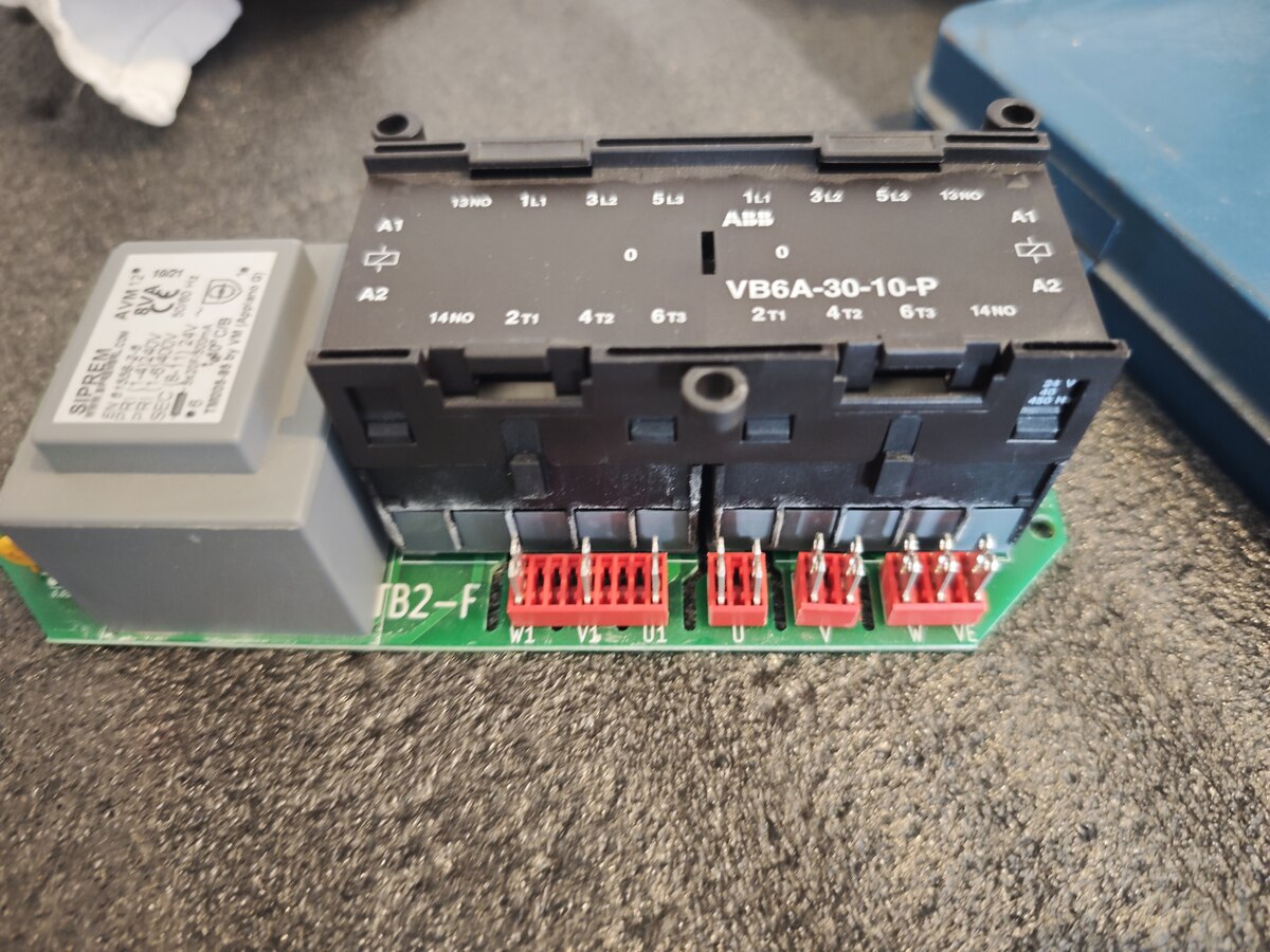
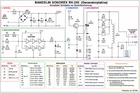
Der Schaltplan liegt mir vor bzw. ist im Viessmann Forum zu finden: https://community.viessmann.de/t5/Sonstige-Produkte/Rostreinigung-F9-GetriebemotorVitoligno-300-P-VL3B-Fast/td-p/39910 Die Schaltung besteht aus wenigen günstigen Standardbauteilen: - Brückengleichrichter W04G (B400V/1A) - R1:
. VDD LOAD REGULATION FIGURE 4. VREF LOAD REGULATION 15 13.0 3.5 10 12.5 3.0 ) 2.5 ( 5 E A Y G12.0 T A T VCHG (V) 2.0 E R L R C 0 V 11.5 C C Y 1.5 U A R R M -5 T 11.0 E I A 1.0 N B T -10 10.5 0.5 ICHG (A) -15 10.0 0.0 1 2 3 4 5 6 7 8 0 20 40 60 80 100 120 140 160 AC-ADAPTER CURRENT (A) TIME (MINUTES
CLDO = 10µF, unless otherwise noted. Oscillator Frequency vs Supply Voltage Oscillator Frequency vs R T Shutdown Current vs Temperature 600 600 25 V = V IN_P IN_N z500 z 500 k RT= GND k A20 Y Y ( N400 N 400 N U U R15 E E U F300 F 300 N O O W10 10V A 200 A 200 D I R T 200kΩ I U 16V S S S 5 O100 O 100 4.5V
Elektromaschinebauer auch einen Ersatzmotor auf Lager. Neupreis von der Kiste war meine ich irgendwas an die 200-400 € so grob und 300 € Reparaturkosten stecke ich da bestimmt nicht rein. So ganz grob würde ich sagen sind 40 € genug, deswegen auch Teile von irgendwo gebraucht. So, muss los....
überlastet und wird dann nicht im Leerlauf eine Weile gekühlt, kommt die Stauwärme im Stillstand zur T-Sicherung... Durch "Bastler" dann zu wechseln, für den Normalbürger aus Kostengründen nicht. Gewerblich würde da auch niemand einen höheren Wert einbauen.
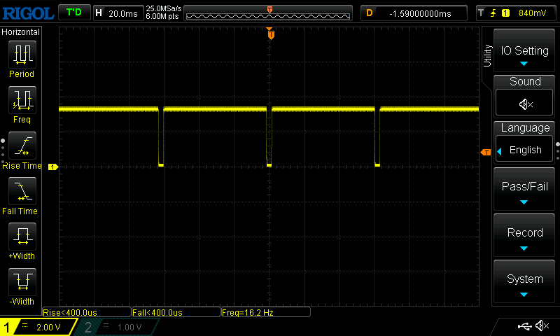
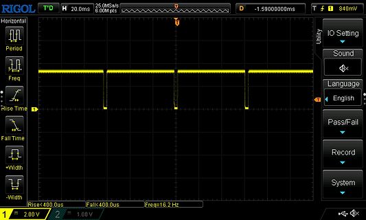
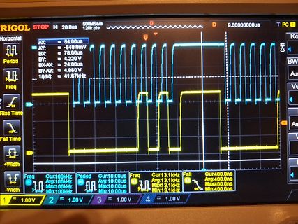
RIGOL T'D H 20.0ms 25.0MSa/s -1.5900000ms T 1 840mV Horizontal Period Freq Rise Time Fall Time +Width -Width IO Setting Sound Language English Pass/Fail Record System Rise<400.us Fall<400.us Freq=16.2 Hz 1 2.00
3.0V -25°C to +85°C 100 µV proprietary multipoint laser compensation VRE117M +3.0V -55°C to +125°C 400 µV technique developed by Thaler Corporation. VRE117MA +3.0V -55°C to +125°C 200 µV Significant improvements have been made in VRE118C -3.0V -25°C to +85°C 200 µV other performance parameters as well
S. schrieb im Beitrag #7998621: > solarbetriebenen Fernbedienung Kein Problem: Wenn Du nun ein 400W-Modul anschließt, kannst Du jetzt im Winter 3 Watt ernten. Dann rechne die kurzen Sonnenstunden aus. 3W*3h=9 Wh Die Ernte reicht dann völlig aus, um Deinen ESP bei *Sonne* zu betreiben. 8-)
Anwendungen wirtschaftlich, bei denen man im Feld gar nicht mehr dran kommt für Batteriewechsel, z.B. IoT-Sensorknoten die irgendwo in der Landschaft sitzen. Und natürlich für Spaßprojekte 🙃
time, EN/PWM fallingLED I ILED= 175 mA 400 ns I = 80 mA 300 LED T LED rise time I = 175 mA 700 ns R LED ILED= 80 mA 440 TF LED fall time ILED= 175 mA 360 ns ILED= 80 mA 320 TLO EN/PWM low time 1 ms T HI EN/PWM high time 5 ms T PWRDWN EN/PWM
is used as a legal measuring instrument, all units except g/kg are blocked. No stability parameter t l t Taiwanese taels o * * Grams (o) GN Grains * * * g * * Grams d w t Pennyweights k g * Kilograms / l b Parts per Pound c t * Carats t l c Chinese taels l b * Pounds m o m Mommes o z * Ounces K * * Austrian carats o z t Troy ounces t o l Tola t l h Hong Kong taels b a t Baht t l s Singapore taels MS * Mesghal * = space, U = Unit 4–4 Special Codes Special codes are output only if the scale operating menu code 611,614
and —15,5V. ® Connect the PM2521/22 to the mains and check the charging current isbetween 5mA and 400mA. : 5. P A R T S LIS T 5.1, R E S I S T O R S : Ordering number Value (92) Tol. (%) [tem 5322 116 55615 20 5% R101 : 5322 116 55614 6,49 0,5% R102 : 5322 116 55614 6,49 0,5% R103 ‘ 5322 116 54502 216
100 µA CC Shutdown Mode (RPROGNot 45 100 Connected,VCC < BAT, orCC < V UV Regulated Output (Float)0℃≤T ≤A5℃,I BAT=40mA 4.15 4.2 4.242 V VFLOAL Voltage 8 BAT Pin Current R PROG = 10k, Current Mode ● 90 100 110 mA R = 1.66k, Current Mode PROG ● 250 400 450 mA Standby Mode, VBAT= 4.2V ● 0 -2.5 -6 µA BAT
ShenZhenJingdao Electronic Co.,Ltd. 4. Application 4.1 Scope of Application LED fluorescent tubes (T5/T8/T10…) LED bulbs/corn lamps/candle lamps… Other low- power LED lighting 4.2 Typical Applications F1 LED AC 7(1) IN OUT REXT JD9203ES06 C1 (JD 203C)S06 2(3) GND R2 1(2) Figure 2. Application scheme
1500W > 1.5KE series Soldering Parameters Reflow Condition Lead–free assembly p P -Temperature Min (T s(min) 150°C Ramp-up Critical Zone TLtoPT Pre Heat -Temperature Max (T s(max) 200°C L tL T -Time (min to max) (s ) 60 – 180 secs es(max) t Average ramp up rate (LiquidusTemp (T )A e Ramp-down 3°C/second max ps(min) to peak e Preheat T T S(max)T A Ramp-up Rate 3°C/second max -Temperature (T ) (Liquidus) 217°C 25˚C Reflow A t 25˚C to Peak -Time (min to max) (t ) 60 – 150 seconds Time (t) s PeakTemperature (T ) 260 +0/°C P Time within
through the installation openihg (connection area for 230 V / 400 V i ) into the housing lower pa1t and connect according to the circuit diagram (Fig. 7) to the terminkl (as described in subsections in 3). 5.4. Connecting the fan (optional) ●● Guide the fan lines
(Vcc = 2.7 ~ 4.2 V,AT = -25 ~ 85 C, unless otherwise noticed. Typical values are at Vcc = 3.3VAand T = 25 C). SYMBOL PARAMETER CONDITIONS MIN TYP MAX UNIT 2 fSCL I C clock frequency 400 kHz t Clock Low time 1.3 LOW s t Clock High time 0.8 s HI SCL input to SDA ST falling edge start,3 0.6 s SDA falling
übrig weil ich die zugehörigen Netzteile/Akku versehentlich entsorgt habe. 1. ein Dymo Labelwriter 400 (Software bis W11 auf Webseite vorhanden) Preis =25€ VB 2. ein blauer Bosch Akkuschrauber GSR 9.6 VES-2 Preis =20€ VB Der Drucker braucht ein 24V Netzteil mit Hohlstecker und funktionierte bis
T. K. schrieb im Beitrag #8079281: > Versand wählbar mit Hermes/DHL zu jeweils ca. 7€. Manchmal ist die Hermes-Annahmestelle näher als der Abfallhof.
CMOSoutput active“H” S-8264AAG-I8T1U 4.300 ±0.025 V −0.390 ±0.160 V 2.0 ±0.4 s CMOSoutput active“H” S-8264AAH-I8T1U 4.400 ±0.025 V −0.390 ±0.160 V 4.0 ±0.8 s CMOSoutput active“H” S-8264AAI-I8T1U 4.400 ±0.025 V −0.390 ±0.160 V 2.0 ±0.4 s CMOSoutput active“H” S-8264AAJ-I8T1U 4.450 ±0.025 V −0.390 ±0.160 V 5.65 ±1.15 s CMOSoutput active“H” S-8264AAK-I8T1U 4.350 ±0.025 V −0.390 ±0.160 V 5.65 ±1.15 s CMOSoutput active“H” S-8264AAO-I8T1U 4.400 ±0.025 V −0.390 ±0.160 V 5.65
FORTH AT www.vishay.com/doc?91000 SQJQ160E www.vishay.com Vishay Siliconix TYPICAL CHARACTERISTICS (T = 25 °C, unless otherwise noted) A Axis Title Axis Title 500 10000 500 10000 VGS= 10 V thru 6 V 400 400 ) ) ( 1000 ( 1000 n 300 n 300 e r e n e r e n l u l l l u T = 25 °C l l d C s n d C C s n 2 a 200
parameters to their previous values. • To ensure that the desired parameter is kept constant, we suggest tENTER- 1∫1 set all other parameters to maximum. END METHOD: YES • A blinking unit of the controlling parameter appears when the regulation is • The timer will always count down. RUN 1∫1 99:59h 400V 500mA

 Bild
 Bild
 Bild
 Bild
 Bild