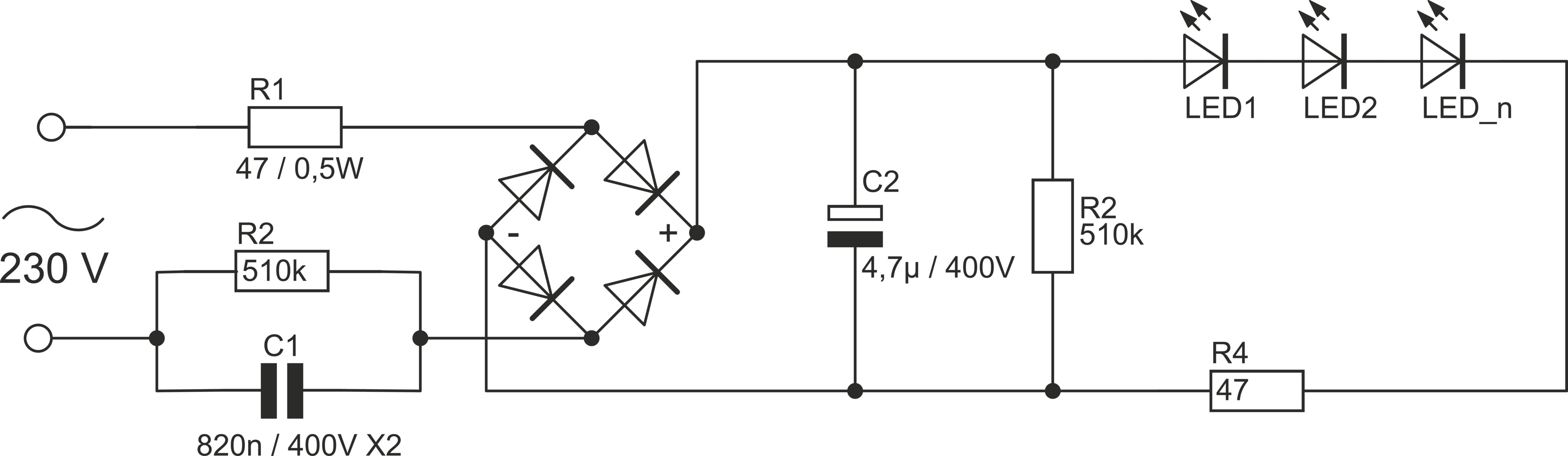
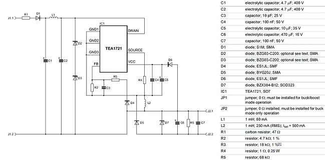
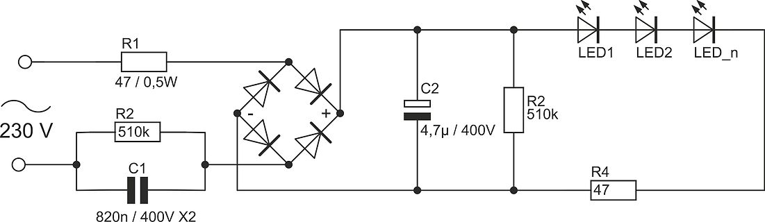
P (V 1.414)V V 1.414 IN AC f AC 其中 V AC是 AC 输入电压, Vf是单个 LED 工作时的电压降, f 是 LED 的工作电流。 线路中串联的 LED 数量 N 越大,系统工作效率越高。 设计过程中,可以根据实际应用条件合理调节 V1,优化效率。 6.3 恒流控制,输出电流设置 JD9203ES06 可以通过外部电阻精确的设定工作电流。工作电流计算公式: VREXT I R2 注:布 PCB 线路时芯片要有良好的散热环境。 电解电容 C1 值越大,电压 Vin 纹波越小,供给 JD9203ES06 工作的电压纹波 也越小。C1 值根据 LED 灯管总工作电流而定:电流越大,C1 容量越大,一 般取值 4.7uF/400V~22uF/400V。 6.4 过温调节功能 为了提高芯片工作可靠性,JD9203ES06 采用过温调节设计,当驱动电源过热 时,逐渐减小输出电流,从而控制输出电流及温升,使电源温度保持在设定值,以 调高系统可靠性
and Cannon Fodder. Here are some rough numbers against ao486: [/c] ### RISC/V-Kern für GoWin GW1N-9 FPGA Softcore Nummero zwei ist ein an der Universität zu Turin entwickelter RISC/V-Chip, der auf dem Kongress-Abzeichen des in Italien stattfindenden RISC/V Summit zum Einsatz kommen soll. Weitere
7463209307203928064-RpLg/?utm_source=share&utm_medium=member_desktop&rcm=ACoAAAExd_4B88eg3uiygKywlAVeiUfK1nTPfSk ### Reichweitenerhöhung für Drohnen durch Heliumballons Während die Nutzung von Glasfaser die Störproblematik im Drohnen-Bereich löst, gibt es für die geringe zur Verfügung stehende Energiemenge
(PDN=VSS) i.e. at the falling edge of PDN signal. 6) Receiver inputs RFIP and RFIM have both 1.4 MΩ biasing resistors towards VDD 8 (12) DA6180C.001 17 September, 2014 PACKAGE (TSSOP-16) OUTLINES C E D Seating Plane B F G H A O Pin 1 B Detail A B L I I1 K P Section B-B J1 M Detail A J N Dimension
T E C H N I S C H E D AT E N AGF A MUL TICONTRAST - 1 CLASSIC 40 0 500 AGFA MULTICONTRAST CLASSIC ist ein gradations- variables Schwarzweiß-Fotopapier auf Baryt-Unterlage. Eigenschaften: ● Universelles Schwarzweiß-Vergrößerungspapier
commercial environments Safety related data safe state Load circuit open function test interval maximum 1 a diagnostics test interval by internal test function maximum 600 s stop category according to IEC 60204-1 0 B10d value 2 500 000 failure rate [FIT] at rate of recognizable hazardous failures 1 400 FIT
Pin Configuration ISL88731 Applications (28 LD TQFN) TOP VIEW • Notebook Computers • Tablet PCs P N T T S N S S C O G H C • Portable Equipment with Rechargeable Batteries C C V B U P D 28 27 26 25 24 23 22 Ordering Information NC VDDP 1 21 PART ACIN 2 20 LGATE NUMBER PART TEMP PACKAGE PKG. (Notes 1
Das eigentliche Problem / die philosophische Frage: Ich habe ein Board entworfen mit ISZ0702NLSATMA1 als (High- und Low-Side-)MOSFET. Der ISZ0702NLSATMA1 ist ziemlich klein, soll aber bis zu 86 A können (bei entsprechender thermischer Anbindung). Ich wundere mich etwas, da bei den MOSFETS das Drain-Pad
Jetzt wäre meine erste Idee, einfach einen größeren MOSFET mit einem größeren Pad zu verwenden. Der RJ1L04BBGTL1 sieht vielversprechend aus. Aber deshalb die philosophische/grundsätzliche Fragen: Die MOSFETs mit dem großen thermischen Pad und insgesamt kleinen Bauform (3mm x 3mm) scheinen "state-of-the-art
Clock-Takte für den RX-Tayloe verwendet und ein Clock für den TX. Diese werden durch die Konstanten TX1RX0, TX0RX1, TX0RX0 und TX1RX1 entsprechend aktiviert bzw. deaktiviert, wobei mir die letzte Konstante etwas unklar ist. Ab Code-Pos. 518 ... [c] #ifdef TX_CLK0_CLK1 #ifdef F_CLK2 #define TX1RX0 0b11111000 // 248 (10) F8 (hex) #define TX1RX1 0b11111000 #define TX0RX1 0b11111000 #define TX0RX0 0b11111011 // 251 (10) FB (hex) #else //!F_CLK2 #define TX1RX0 0b11111100 // 252 (10) FC (hex) #define TX1RX1 0b11111100 #define TX0RX1
. Danke Peter, aber Hitzetod sehe ich nur bedingt: in 3 der Geräte waren beide MosFets (zB FHA20N50) ordentlich auf Kühlkörper, mit Glimmerscheibe und Paste verbaut.
aber nicht reinstecke. Vorhin habe ich das hier gefunden https://de.ifixit.com/Document/iWm6Aba1UKxgnoQ3/EMMI-12HC.pdf?referrer=wiki%3A632829 Interessant ist: mein 12HC hat definiv eine andere Platine bzw Bestückung.
. Aber immerhin... https://ve6aqo.com/Semco-top.htm https://ve6aqo.com/funkschau1.htm
Aber du hast natürlich recht, mein allererstes Gerät wurde noch mit einer Aluplatte der Stärke von 1,5 mm gefertigt. Bei 1,5 mm Stärke verformt sich die Aluplatte dann doch zusehenst.
by the following formula: ÿ 1.414 ÿ 1 In N ÿ AC VV f Where V1 is the voltage drop across the IC during operation (i.e., VOUT), which can be adjusted according to the heat dissipation conditions in the actual application. When adjusting
Updates. Stand: Firmware-Updates sowohl von DSP, als auch RF-Modul kann ich sowohl bei meinem HM-400, als auch HMS-600 over-the-air machen. Dafür gibts eine fancy webapp, die aber noch ein custom board mit STM32+nRF24 braucht mit dem sie dann via websock über ttyACM spricht. Also geht erstmal nicht
Im Prinzip ist Firmwareupdate ein "gefährliches" Feature, weil: 1) Keine A/B Firmware. Wenn Update fehlschlägt ist der Inverter unbrauchbar bis wieder eine gute Firmware drauf ist 2) Missbrauchspotential (gibt nur CRCs, keine digitalen Signaturen) Das ganze ist
1.8 VGS = 10V ( s t 100 e 1.6 e n r O C T = 175°C e ) 1.4 e J u e r 10 o l1.2 o - a - - o - i (1.0 i r r TJ= 25°C , , 1 n 0.8 ID ( VDS = 15V S 0.6 RD ≤60µs PULSE WIDTH 0.1 0.4 1 2 3 4 5 6 7 8 -60 -40 -
TYP. MAX. UNIT VBAT supply voltage on pin BAT 5 12 27 V BAT supply current on pin BAT in sleep mode 1 3 8 A supply current on pin BAT in standby mode; bus recessive 100 400 1000 A supply current on pin BAT in normal slope mode; bus recessi100 400 1000 A supply current on pin BAT in normal slope mode;
0.02% + 3 mA Stability, constant load & temperature ± (% of output + offset), 8 hrs Voltage 0.03% + 1 mV 0.02% + 2 mV 0.02% + 1 mV Current 0.1% + 3 mA 0.05% + 1 mA 0.1% + 1 mA Remote Sense (max. voltage in each load lead) N/A 1 V 0.7 V Voltage Programming Speed, to within 1% of total excursion Up Full
. D MX- e est uer terB etrieb Übe rhre n D X-Con tr ler önnen Sie die einzenen G eräte nd idue l n tu r n. Dabeih t jder DM X- Kanal eine nd e eel egung m it er chiedenen Ege nschafe n. 13/55 00020552.DOC, Version 1.5 DMX-Protokoll Steuerkanal
die Funktion InitEndpoints(void) in die pragmas packe, also so: [code] #pragma GCC optimize ("O1") InitEndpoints(void) { trace("InitEndpoints\n"); USB_CNTR = 1; // disable reset and int CMD.Configuration = 0; // nothing before CONFIGURED CMD.TransferLen = 0; // nothing
the adjacent `uint16_t` fields into word / doubleword stores: ```asm 8000480: strd r2, r4, [r1, #400] @ 0x40006190 TxOffset|TxCount as one 32-bit word @ 0x40006194 RxOffset|RxCount as one 32-bit word 8000486: strd r0, r4, [r1, #408] @ entry 1, again 2 x
(T = 25 °C, unless otherwise noted) A Axis Title Axis Title 500 10000 500 10000 VGS= 10 V thru 6 V 400 400 ) ) ( 1000 ( 1000 n 300 n 300 e r e n e r e n l u l l l u T = 25 °C l l d C s n d C C s n 2 a 200 V = 5 V 1 2 2 a 200 1 2 D GS D - 100 - 100 I I 100 100 TC= 125 °C VGS= 4 V TC= -55 °C 0 10 0 10
MF, AMB = 25°C UNLESS OTHERWISE SPECIFIED.) 1.2 8 A No Load A ( ( T 1.0 T 6 N N R R R R C 0.8 C 4 T T N N C C S S I 0.6 I 2 U U Q Q 0.4 0 3.0 3.5 4.0 4.5 5.0 5.5 0 0.5 1.0 1.5 2.0 INPUT VOLTAGE (V) RSET CURRENT (mA) Figure 3. Quiescent Current vs
in the container + 17.2gcs Press the u/w key, begin counting + 20pcs Data output nRef + 20 pcs wRef + 0.8700 g Press the S/a key + 20pcs nRef + 20 pcs to store value in the wRef + 0.8700 g totalizing memory. n 1 Transaction counter: 1 N + 17.7 g 1st partial value Qnt + 20 pcs * = factory
ausfallen, da übliche Relaisanwendungen nur mit geringen Frequenzen schalten (einige Hertz). Eine kleine 1N4148 (Nachfolger der 1N914) kann für bis zu 1 A eingesetzt werden. Allerdings lohnen sicht derartige Tricksereien kaum noch, da Dioden sehr billig sind. Wer auf Nummer sicher gehen will nimmt eine Diode, deren Nennstrom größer oder gleich dem Relaisstrom ist. Einfache Gleichrichterdioden wie z. B. 1N400x sind hier entgegen der oft gehörten Meinung ausreichend, es müssen keine schnellen Schaltdioden verwendet werden. Denn entscheidend für die Freilaufdiode ist die Einschaltzeit (forward recovery

 Bild
Bild
 Bild
Bild
 Bild
Bild
 Bild
Bild
 Bild
Bild
 Bild
Bild
 Bild
Bild
 Bild
Bild
 Bild
Bild
 Bild
Bild
 Bild
Bild
 Bild
Bild
 Bild
Bild