
-
Datei
meindef.h
typedef uint16_t u16; typedef int16_t s16; typedef uint32_t u32; typedef int32_t s32; typedef uint64_t u64; typedef int64_t s64; typedef __uint24 u24; typedef __int24 s24; // unions, die Arbeit mit Bytes und Bits innerhalb des Wortes erleichtern typedef struct{ u8 bit0:1; u8 bit1:1; u8 bit2:1; u8 bit3
in „I2C Display einfache Frage“ · Mikrocontroller und Digitale Elektronik ·
-
Datei
disassebled_original_working.asm
.107+0x46> 28a6: 9b 01 movw r18, r22 28a8: 61 34 cpi r22, 0x41 ; 65 28aa: 71 05 cpc r23, r1 28ac: 10 f0 brcs .+4 ; 0x28b2 <_ZN7TwoWire11requestFromEhjb.constprop.107+0x2a> 28ae: 20 e4 ldi r18, 0x40 ; 64 28b0: 30 e0
in „Bizarrer Firmware crash - ATmega4808. Wie Debuggen?“ · Mikrocontroller und Digitale Elektronik ·
-
Datei
disassebled_minimal_change_crash.asm
.107+0x46> 28a6: 9b 01 movw r18, r22 28a8: 61 34 cpi r22, 0x41 ; 65 28aa: 71 05 cpc r23, r1 28ac: 10 f0 brcs .+4 ; 0x28b2 <_ZN7TwoWire11requestFromEhjb.constprop.107+0x2a> 28ae: 20 e4 ldi r18, 0x40 ; 64 28b0: 30 e0
in „Bizarrer Firmware crash - ATmega4808. Wie Debuggen?“ · Mikrocontroller und Digitale Elektronik ·
-
Datei
Lambdacontroller_ai_claude_2.ino
#include <Arduino.h> #include <SPI.h> #include <avr/io.h> #include <util/delay.h> #include <avr/pgmspace.h> // ----------------------------- // Pin-Zuordnung MegaCore AT90CAN64 // ----------------------------- #define CJ125_CS_PIN 8 // PB0 #define HEATER_OUTPUT_PIN
in „Bosch CJ125 mit AVR AT90CAN64“ · Mikrocontroller und Digitale Elektronik ·
-
Datei
Lambdacontroller_ai_claude.txt
#include <Arduino.h> #include <SPI.h> #include <avr/io.h> #include <util/delay.h> #include <avr/pgmspace.h> // ----------------------------- // Pin-Zuordnung MegaCore AT90CAN64 // ----------------------------- #define CJ125_CS_PIN 8 // PB0 #define HEATER_OUTPUT_PIN
in „Bosch CJ125 mit AVR AT90CAN64“ · Mikrocontroller und Digitale Elektronik ·
-
Datei
oled_demo.c
-- Controllerspezifisches ------------------------------------------------------------ */ #ifdef __AVR__ /* ------------------------------------------------------------ AVR-Mikrocontroller ------------------------------------------------------------ */ #include <avr/io.h> #include <avr/pgmspace.h> #include
in „I2C Display einfache Frage“ · Mikrocontroller und Digitale Elektronik ·
-
 Bild
Bild
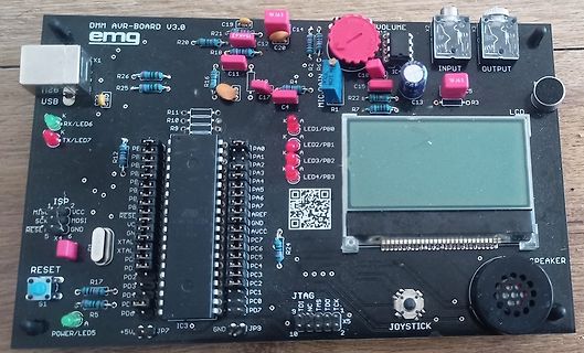
DMM AVR-BOARD V3.0 Leiterplatte mit LCD und Joystick
DMM AVR-BOARD V3.0 emg X1 USB LED6 RX/ LED7 TX R11 C19 R16 C12 C20 C15 R21 R18 C11 R25 R26 R12 R10 R9 R1 R2 R3 R24 R17 R5 R4 R13 R14 R15 R19 R20 R22 R23 R27 R28 R29 R30 R31 R32 R33 R34 R35 R36 R37 R38 R39 R40 R41 R42 R43 R44 R45 R46 R47 R48 R49 R50 R51 R52 R53 R54 R55 R56 R57 R58 R59 R60 R61 R62 R63 R64 R65 R66 R67 R68 R69 R70 R71 R72 R73 R74 R75 R76 R77 R78 R79 R80 R81 R82 R83 R84 R85 R86 R87 R88 R89 R90 R91 R92 R93 R94 R95 R96 R97 R98 R99 R100 R101 R102 R103 R104 R105 R106 R107 R108 R109 R110 R111
in „Suche Unterlagen zum DMM AVR-BOARD V3.0 der TU Braunschweig“ · Mikrocontroller und Digitale Elektronik · · Platinenfotos
-
Datei
oled_2313demo.c
12 | PB0 - AIN0 - PCINT0 GND | 10 11 | PD6 - ICP +-------------+ */ #include <stdint.h> #include <avr/io.h> #include <avr/pgmspace.h> #include <util/delay.h> /* ------------------------------------------------------------ Konfiguration ------------------------------------------------------------ */
in „I2C Display einfache Frage“ · Mikrocontroller und Digitale Elektronik ·
-
Datei
Schrittmotor.asm
Test- ;Zurueck: .ORG 0x0100 ; Adresse 0x200 MTab: .db 0,2,3,5,6,8,9,11,13,14,16,17,19,20,22,24,25,27,28,30,31,33,34,36,38,39,41,42,44,45,47,48 .db 50,51,53,55,56,58,59,61,62,64,65,67,68,70,71,73,74,76,77,79,80,82,83,85,86,88,89,91,92,94,95,96 .db 98,99,101,102,104,105,107,108,109,111,112,114,115,116,118,119,121,122,123,125,126,128,129,130,132,133,134,136,137,138,140,141
in „Spielerei mit einem 2- und 5-Phasen-Schrittmotor“ · Projekte & Code ·
-
Datei
Schrittmotor.asm
Test- ;Zurueck: .ORG 0x0100 ; Adresse 0x200 MTab: .db 0,2,3,5,6,8,9,11,13,14,16,17,19,20,22,24,25,27,28,30,31,33,34,36,38,39,41,42,44,45,47,48 .db 50,51,53,55,56,58,59,61,62,64,65,67,68,70,71,73,74,76,77,79,80,82,83,85,86,88,89,91,92,94,95,96 .db 98,99,101,102,104,105,107,108,109,111,112,114,115,116,118,119,121,122,123,125,126,128,129,130,132,133,134,136,137,138,140,141
in „Spielerei mit einem 2- und 5-Phasen-Schrittmotor“ · Projekte & Code ·
-
PDF
Micrel.pdf
like is provided only for your convenience The Microchip name and logo, the Microchip logo,AnyRate,AVR, and may be superseded by updates. It is your responsibility to AVR logo, AVR Freaks, BitCloud, chipKIT, chipKIT logo, ensure that your application meets with your specifications. CryptoMemory, CryptoRF
-
Datei
t13-charlieplexing.asm
; ; *********************************** ; * (Add program task here) * ; * (Add AVR type and version here) * ; * (C)2021 by Gerhard Schmidt * ; *********************************** ; .nolist .include "tn13adef.inc" ; Define device ATtiny13A .list ; ; ********************************
in „Attiny13a stürzt ab“ · Mikrocontroller und Digitale Elektronik ·
-
Datei
t13-charlieplexing.asm
; ; *********************************** ; * (Add program task here) * ; * (Add AVR type and version here) * ; * (C)2021 by Gerhard Schmidt * ; *********************************** ; .nolist .include "tn13adef.inc" ; Define device ATtiny13A .list ; ; ********************************
in „Attiny13a stürzt ab“ · Mikrocontroller und Digitale Elektronik ·
-
PDF
Sinuswechselrichter.pdf
verbaut. MOSFETs besitzen ein Kennlinien- feld, das sich in drei Bereiche aufteilt, siehe Abbildung 28. 36 3 Hardwareanalyse 3 Hardwareanalyse Abbi ldungg 28: Kennlinie des MOSFET IRFZ44N [14] mit qualitativer Einteilung der Ken linienber iche nach J. Specovius [16] Kennlinienbereiche nach J. Specovius
in „Wechselrichter Spannung und Frequenz steuerbar für Teichpumpe“ · Haus & Smart Home ·
-
PDF
hitag2_hacken.pdf
deployed in the late nineties, such as Kee- 1http://www.nxp.com/products/automotive/ loq [ 8, 13, 27, 28], MIFARE Classic [12, 19, 22, 35], car access immobilizers/immobilizer/ CryptoMemory [4, 5, 23] or iClass [20, 21]. Originally, 2 information on Hitag2 transponders was limited to data ure vulnerable
-
Datei
font_graph.c
, // 33 = 0x21 <!> 0x00,0x14,0x14,0x14,0x00,0x00,0x00,0x00,0x00,0x00,0x00, // 34 = 0x22 <"> 0x00,0x28,0x28,0x7C,0x28,0x14,0x3E,0x14,0x14,0x00,0x00, // 35 = 0x23 <#> 0x08,0x1C,0x0A,0x0A,0x0C,0x18,0x28,0x28,0x1E,0x08,0x00, // 36 = 0x24 <$> 0x00,0x47,0x25,0x15,0x0F,0x3C,0x2A,0x29,0x38,0x00,0x00, // 37 =
in „Lib für Arduino Giga machen“ · Mikrocontroller und Digitale Elektronik ·
