ΔV /ΔT −40°C ≤T ≤ +85°C OS A C = 100 µA,VCB 0V 0.4 2 µV/°C BreakdownVoltage BV CEO C = 10 µA 40 V −40°C ≤T A +85°C 40 V Gain-Bandwidth Product fT C = 1 mA,V CE10V 300 MHz Collector Leakage Current Base ICBO VCB 40V 5 pA −40°C ≤T ≤ +85°C 0.5 nA A Substrate ICS VCS 40V 0.5 nA −40°C ≤T A +85°C 0.7 nA Emitter ICES VCE 40V 3 nA −40°C ≤T A +85°C 5 nA Input Current Bias IB C = 100 µA, 0V ≤V CB30V 165 330 nA −40°C ≤T ≤ +85°C 200 500 nA A
IEEE 802.3 for 10BaseT IEEE 802.3u for 100BaseT(X) and 100BaseFX IEEE 802.3x for flow control Optical Fiber 100BaseFX Multi-Mode Fiber Cable Type OM1 OM2 OM3 OM4 Typical Distance 4 km 4 km 4 km 4 km TX Range 1260 to 1360
Simplified Chinese 1 x quick installation guide 1 x warranty card Dimensions Ordering Information 100BaseFX 100BaseFX 100BaseFX Total No. of 10/100BaseT(X) Ports Ports Ports Model Name Layer Ports Operating Temp. Ports RJ45 Connector Multi-Mode SC Multi-Mode ST Single-Mode SC Connector Connector Connector
2 km Standards IEEE 802.3 for 10BaseT IEEE 802.3u for 100BaseT(X) and 100BaseFX IEEE 802.1X for authentication IEEE 802.1D-2004 for Spanning Tree Protocol IEEE 802.1w for Rapid Spanning Tree Protocol IEEE 802.1s for Multiple Spanning Tree
electronic Smaller than your thumb, it includes all essential networking features, including a 10Base- device T/100Base-TX Ethernet connection, proven operating system, an embedded web server, e-mail • Remote command and control of edge alerts, a full TCP/IP protocol stack and 256-bit AES encryption
Hallo zusammen, ich habe einen Tiny85 mit der Library von mchr3k/arduino-libs-manchester geflasht, um Daten an einen Raspberry Pi Model 1B zu senden. Die GPIOs des Raspberry Pi werden über die Schnittstelle pigpio angesprochen. Daher hatte
Manchester kann man schon mit den nur 35 Befehlen der Base-PICs sehr einfach dekodieren. Oder mit einem Z80 mit einem 1 MHz Takt. Versuchs noch einmal etwas hardwarenäher. Dabei lernst du dann auch, wie man auf die GPIOs z.B. in C zugreifen kann. Für
, ARP, ICMP, Auto-IP, DNS • SNMP v1/v2 • IPv6 Ethernet Specifications • IEEE 802.3 MAC and PHY, 10BaseT and 100BaseT with Auto-MDIX • Auto Negotiation; Full duplex and half duplex support • Link Activity LED Indicators Serial Interface Specifications • 1x UART (Serial) Ports • CMOS (Asynchronous) 3.3V
, ARP, ICMP, Auto-IP, DNS • SNMP v1/v2 • IPv6 Ethernet Specifications • IEEE 802.3 MAC and PHY, 10BaseT and 100BaseT with Auto-MDIX • Auto Negotiation; Full duplex and half duplex support • Link Activity LED Indicators Serial Interface Specifications • 1x UART (Serial) Ports • CMOS (Asynchronous) 3.3V
designed by ON Semiconductor, includes a PFC circuit which drives the converter with a Global Efficiency: 85% 2 5 μs 10 mV 1 I = 500 mA/DIV C 1 5 μs 10 mV 2 B = 100 mA/DIV 5 μs 1 10 mV 50 Ω 200 MS/s 2 10 mV 50 Ω 1 DC 9 mV j STOPPED LINE = 230 V LOAD = 58 W Figure 26. Collector and Base Currents in Steady State
20k-Poti verwenden - gibt es, ist aber eher unüblich. Die 4 Spannungsquellen in Reihe zu den Basen sind nur zu testzwecken (flat(2m) bedeutet, dass bei jedem Simulationslauf die Spannung zufällig gleichverteilt zwischen -2mV und +2mV festgelegt wird) um nachzuvollziehen, wie groß die Abweichungen
100ns Auflösung und einen 12-Bit ADC für das Poti. Der TCXO KT2016 liefert 10MHz mit 0.5ppm @ -30...+85°C. Die Daten scheinen mir ausreichend zu sein ;) Knapp wird es evt. mit einem 10-Gang Poti, dann ist die Auflösung nur ca. 1/400 Umdrehung. Wenn ±1% Drift @ 0...85°C ausreicht, kann man den KT2016
oscillator frequencyÿ180KHz(Typ.) step-up DC/DC converter can be constructed of l High Efficiencyÿ85%(Type) ME2108Xxx wi th only three external components. l PACKAGEÿ▯ SOT-23ÿ▯ SOT-23-3ÿ▯ SOT-89-3ÿ▯ Also available is a CE(chip enable) function that SOT-89-5 reduce power dissipation During shut-down
Support 1b 1 = 100BASE-TX full duplex is supported by the local device 0 = 100BASE-TX full duplex is not supported 7 TX_HDX RW 100BASE-TX Support 1b 1 = 100BASE-TX half duplex is supported by the local device 0 = 100BASE-TX
30 30 30 Temperature: Operating °C –30 to +70 –30 to +70 –30 to +70 –30 to +70 Storage °C –30 to +85 –30 to +85 –30 to +85 –30 to +85 Agency Approvals UL, CE, CSA, UL, CE, CSA, UL, CE, CSA, UL, CE, CSA, RoHS; UKCA UKCA UKCA UKCA * Compatible with Raspberry Pi G4IDC5-SWandG4IDC5-SWNCmodules See page
II 26) RV4005: Sawtooth start position 27) RV9004: X-Magnification x1 28) CV4001: 0.5 μs/div time base adjustment 29) RV4004: 50 μs/div time base adjustment 30) RV4003: 50 ms/div time base adjustment 31) RV9003: X-Magnification x10 33) RV9002: X-Gain Adjustment in XY-Mode CR Board 1 Before removing the
00000028 T HAL_SYSTICK_Config 08000387 00000008 T HAL_SYSTICK_IRQHandler 08001b35 00000060 T HAL_TIM_Base_Init 08003225 0000004e T HAL_TIM_Base_MspInit 08001b99 00000002 W HAL_TIMEx_Break2Callback 08001b97 00000002 W HAL_TIMEx_BreakCallback 08001b95 00000002 W HAL_TIMEx_CommutCallback 08001e83 00000004
laufen der mir die Statistiken ausliest / speichert. Als Code-Completion habe ich qwen2.5-coder:1.5b-base - sehr schnell und macht was es soll: [code] name: Local Config version: 1.0.0 schema: v1 models: - name: qwen3.5:9b provider: ollama model: qwen3.5:9b apiBase: http://192.168.231.21
option modules - Standalone Applications contain a high-performance microprocessor that allows the base drive to be dedicated to motion control as well as • Motion Control Functionality machine control. - Velocity, Torque Mode - Position-Indexing - Synchronization, Electronic Gearing SM-EZMOTION - CAMS
Empty "No data " // 48 Empty }; const /*PROGMEM*/ int tempis[] = { // Tempi for songs 120,140,108,140,85,80,70,140,140,140, // Values Song 1 - 10 Asa Branca, Take on me, Starwars,Cantina Band, Game of thrones, Fuer Elise, Greensleeves Silent night, Happy birthday, Nokia Ringtone 105,200,144,120,114,88,120,76,160,114
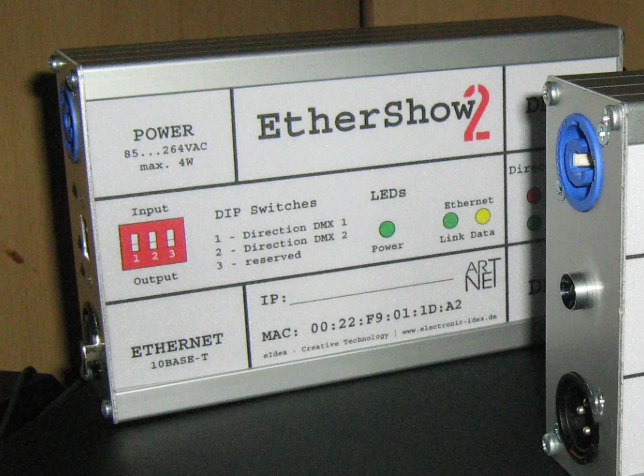
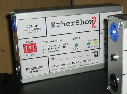
EtherShow2
POWER 85...264VAC max. 4W
Input DIP Switches Output
1 - Direction DMX 1
2 - Direction DMX 2
3 - reserved
LEDs Power Link Data
ETHERNET 10BASE-T
IP:
MAC: 00:22:F9:01:1D:A2
ART NET
eIdea - Creative Technology |
V IL Notes: 1. RFO output at FCC level. Table 5: AC Characteristics (Vcc = 2.7 ~ 4.2 V,AT = -25 ~ 85 C, unless otherwise noticed. Typical values are at Vcc = A.3V and T = 25 C). SYMBOL PARAMETERS CONDITIONS MIN TYP MAX UNIT Fxtal Crystal or Clock 12 or 24 MHz frequency Fxtal_err Crystal frequency Over
Voltage (for ULN2002A/D - 2003A/D - 2004A/D) 30 V Ic Continuous Collector Current 500 mA Ib Continuous Base Current 25 mA Tamb Operating Ambient Temperature Range – 20 to 85 ⋅C T stg Storage Temperature Range – 55 to 150 ⋅C Tj Junction Temperature 150 ⋅C THERMAL DATA Symbol Parameter DIP16 SO16 Unit Rth j-amb
Value Unit VTM (2) TM = 8.5 A p = 380 µs Tj= 25°C MAX. 1.55 V Vt02) Threshold voltage Tj= 125°C MAX. 0.85 V R d(2) Dynamic resistance Tj= 125°C MAX. 60 mΩ DRM Tj= 25°C 5 µA I VDRM = VRRM T = 125°C MAX. RRM j 1 mA Note 1: miniGTis guaranted aGT5max. I Note 2: for both polarities of A2 referenced to A1. 2/
ATMEGA Chips" oder "AVR USB ISP Programmer ATMEL ATMEGA STK500". Die Adapter funktionieren auch mit BasCom (aber auch mit AVR Studio), z. B. mit der Einstellung "STK500 native driver". Man kann die Targetspannungsversorgung per USB zwischen 3,3 und 5V umschalten oder ganz abschalten (per DIP-Schalter)
Sie sind per USB an den PC angeschlossen und arbeiten über einen virtuellen COM-Port. Achtung: In BasCom funktioniert das nur bis COM9. Wenn sich das Gerät z. B. auf COM15 installiert, wird es im BasCom evtl. nicht gefunden. Dann in der Systemsteuerung entsprechend umstellen. USBisp. AVR Programmierdongle
C wave soldering for maximum 5 seconds 260 °C PART NUMBER KEY TS11 - 674 - XX - BK - XXX - RA - D Base Number Actuator Height: Push Force: 43 = 4.3 mm 85 = 8.5 mm 100 = 100 gf 50 = 5.0 mm 95 = 9.5 mm 160 = 160 gf 55 = 5.5 mm 105 = 10.5 mm 260 = 260 gf 65 = 6.5 mm 120 = 12.0 mm 73 = 7.3 mm 135 = 13.5
Min. Max. A0 10.5 10.7 A 330 B0 15.7 15.9 B 1.5 D 1.5 1.6 C 12.8 13.2 D1 1.59 1.61 D 20.2 E 1.65 1.85 G 24.4 26.4 F 11.4 11.6 N 100 K0 4.8 5.0 T 30.4 P0 3.9 4.1 P1 11.9 12.1 Base qty 1000 P2 1.9 2.1 Bulk qty 1000 R 50 T 0.25 0.35 W 23.7 24.3 DS0433 - Rev 22 page 26/34 LM217, LM317 SOT223 package information
WKTPSC 81.1~0 R/W 3 WKT period selections: 00: 15.6ms 01: 31.3ms 10: 62.5ms 11: 125ms @5V PAMOD10 (85h) Function related to: PortA PA1MOD 85.7~4 R/W 1 PA1 I/O mode control PA0MOD 85.3~0 R/W 1 PA0 I/O mode control PAMOD32 (86h) Function related to: PortA PA3MOD 86.7~4 R/W 1 PA3 I/O mode control PA2MOD
every instance of GPIO in the device memory map. Table 13-1. GPIO ports memory map Start address Port Base + 0h Port A Base + 40h Port B Base + 80h Port C Base + C0h Port D Base + 100h Port E NOTE • In S32K14x, GPIO can only be accessed by the core through the cross bar interface at 0x400F_F000. S32K1xx
3 V 0.75 1.2 1.5 MHz PROTECTION AND SOFT START ILIM Switching MOSFET current limit D = DMAX , TA≤ 85°C 1.2 1.8 2.4 A ILIM_Start Switching MOSFET start-up TA≤ 85°C 0.72 A current limit tHalf_LIM Time step for half current limit 6.5 ms V OVP_SW Output voltage overvoltage 36 37.5 39 V threshold THERMAL
0xAA. This register is read/write. Memory Space Configuration Register Name Index Definition Memory base address 0x40 Read/write value indicating the selected memory base address bits[23:16] for bits[23:16] descriptor 0 memory descriptor 0. This is the Boot Prom Space. Memory base address 0x41 Read/write

 Bild
Bild
 Bild
Bild
 Bild
Bild