-
Thread
Reverse Engineering eines LIN Bus
Payload als 2-Byte Wert im Little-Endian Format / 1000 enthalten. In 0x0D wären das Werte wie .. CC 56 bis .. C6 55, also 0x56C6 = 22.214 / 1000 = 22,214 V. Das kommt nicht hin. Auch ist gut erkennbar das Byte 4 der Nachricht immer nur 0x55 oder 0x56 ist und keine anderen Werte annimmt.
1F 08 -> 12721928 -> 12,4 V 00D#8C1CBB2B -> 00 BB 1C 8C -> 12262540 -> 12,0 V 00D#C41CBC2B -> 00 BC 1C C4 -> 12328132 -> 12,0 V 00D#D11CBC2B -> 00 BC 1C D1 -> 12328145 -> 12,0 V 00D#DE1CBC2B -> 00 BC 1C DE -> 12328158 -> 12,0 V 00D#FA1CBC2B -> 00 BC 1C FA -> 12328186 -> 12,0 V 00D#141DBC2B -> 00
-
Thread
Lenovo ThinkPad-P16-G2 - RAM erweitern von 64 auf 128 GB
Die originalen verbauten SODIMM Speicher haben die u.g. Werte [c] Technische Daten MTC16C2085S1SC56BD1 BC Hersteller Micron Technology Herstellernummer MTC16C2085S1SC56BD1 BC Kapazitaet 32GB Bezeichnung DDR5-5600 (2800 MHz) Kurzform 32GB (2Rx8) Bauform 262Pin Bauart
prompte Antwort, ich habe bei Alternate noch das Kingston Modul übersehen. [c] Kingston KVR56S46BD8-32 Details Typ SDRAM-DDR5 Farbe grün EAN 0740617334036 Hersteller-Nr. KVR56S46BD8-32 Serie ValueRAM Kapazität 32 GB Anzahl 1 Stück Bauform SO-DIMM Bestückung zweiseitig Speicherchips
-
Thread
Schutzdioden BJT-Linearregler
durch z.B. einen MPSA43 ersetzen MJE340, MPSA42. > bzw. den Strombegrenzungs-NPN > durch einen BC547C? Ja.
diesem Fall ist es dann besser eine 130 Volt Z-Diode einzusetzen, so wie bei der ersten Schaltung (56k zu 470k).
-
Thread
Garagenfernbedinung defekt
sagt so ziemlich genau 40.685 MHz. Weil du nur dort nachgesehen hast? Schau auch mal bei 13,56MHz.
Zeit hatte ich heute nicht. Quarz prüfen. An einem üblichen µC müsste der mit etwas mehr als 13,56MHz laufen.
-
Thread
Funkschlüssel Peugeot Partner I
ffffffffffffffffffffff5a6a8107b8e03e713040e02d354083dc701f3898207 ffffffffffffffffffffff5a6aacd7886c7864728ca02d35566bc4363c3239464 ffffffffffffffffffffff5a6a827db1d726029bc9e02d35413ed8eb93014de4e ffffffffffffffffffffff5a6abbaa1da02f08dec0e02d355dd50ed017846f606 ffffffffffffffffffffff5a6aa604272ac290806c602d3553021395614840362
ffffffffffffffffffffff5a6a90a063d6f313f7eb202d35485031eb7989fbf58 ffffffffffffffffffffff5a6ab105bc1e84111b7ce02d355882de0f42088dbe6 ffffffffffffffffffffff5a6aa6c7292576adbd18602d3553639492bb56de8c2 ffffffffffffffffffffff5a6a85af8a54511fe234a02d3542d7c52a288ff11a4 Setzt sich zusammen aus 13 identischen
-
 Bild
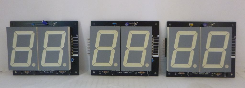
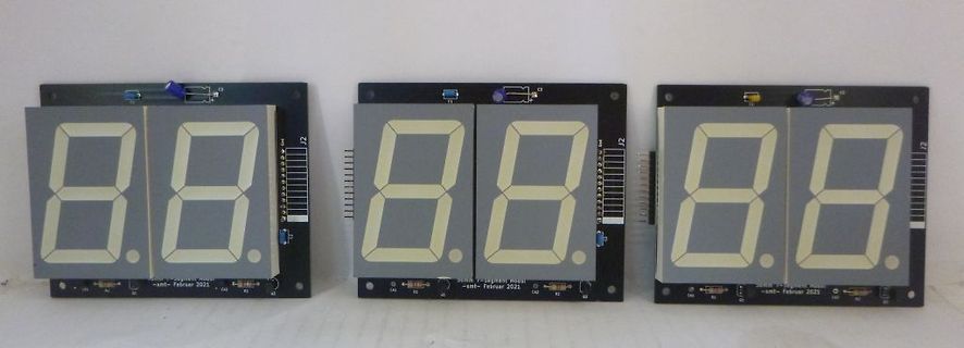
Drei 7-Segment-Anzeigen auf Leiterplatten
J2 -smt- Februar 2021
-
 Bild
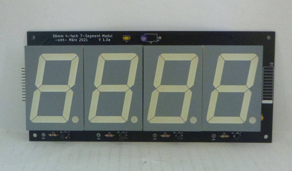
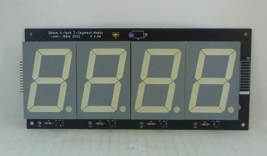
4-stelliges 7-Segment-Display-Modul auf Leiterplatte
56mm 4-fach 7-Segment Modul -smt- März 2021 V 1.0a C1 C5 J2 P1 Q1 E F2 Q2 E C2 C3 Q3 E C4 Q4 E
-
 Bild
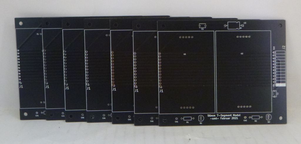
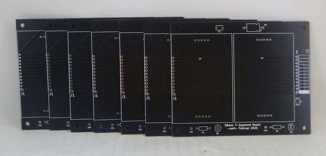
Mehrere schwarze Leiterplatten mit Bestückungsdruck
J1 J1 J1 U1 U2 J2 C1 C2 CA1 CA1 CA1 R1 R2 Q1 Q2 56mm 7-Segment Modul -smv- Februar 2021
-
 Bild
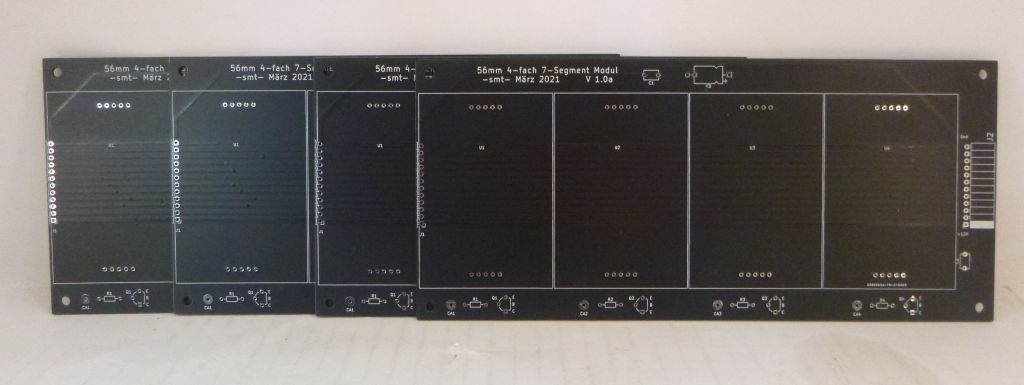
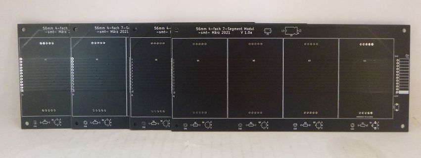
Mehrere unbestückte Leiterplatten für 7-Segment-Module
56mm 4-fach 7-Segment Modul -smt- März 2021 V 1.0a
-
 Bild
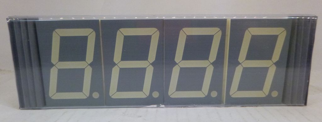
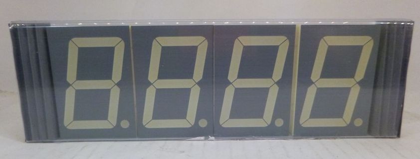
Vierstellige 7-Segment-Anzeige
8.8.8.8.
-
 Bild
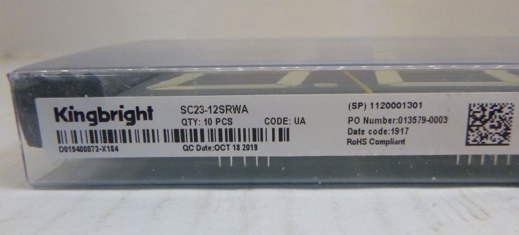
Etikett einer Kingbright-Komponentenverpackung
Kingbright SC23-12SRWA QTY: 10 PCS CODE: UA (SP) 1201301 PO Number: 013579-03 Date code: 1917 RoHS Compliant D0194073-X184 QC Date: OCT 18 2019
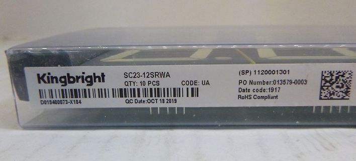
-
 Bild
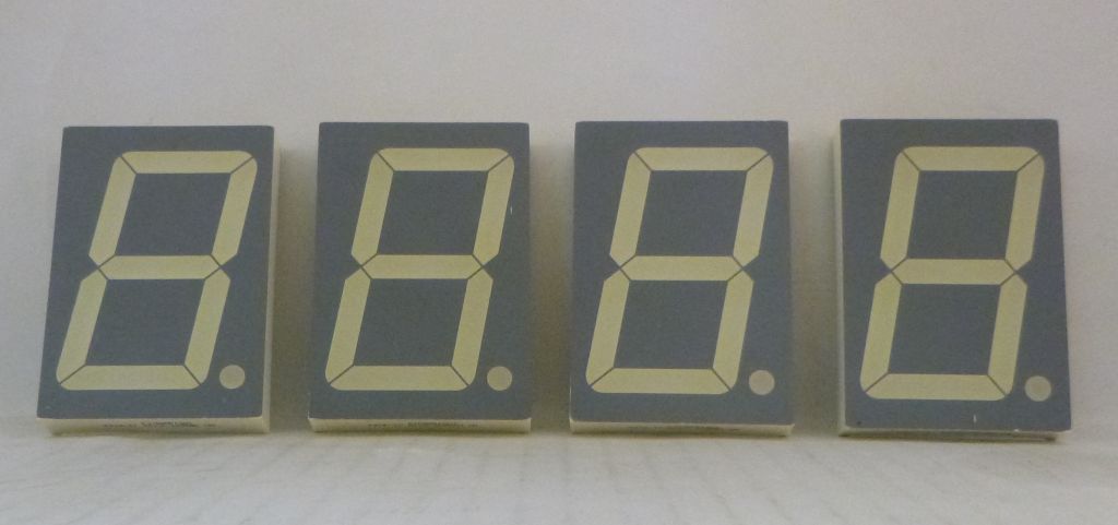
Vier 7-Segment-Anzeigen
8. 8. 8.
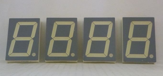
-
 Bild
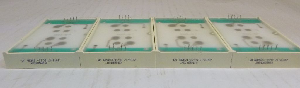
Vier Kingbright LED-Module
KINGBRIGHT 2019-17 SC23-12SRWA UA
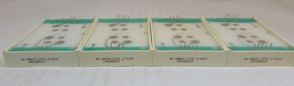
-
 Bild
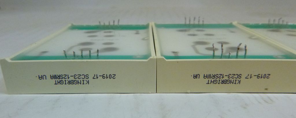
Zwei Kingbright LED-Module
KINGBRIGHT 2019-17 SC23-12SRWA UA.
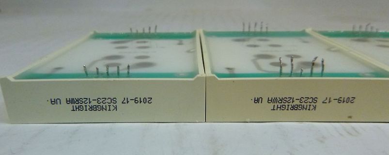
-
 Bild
Schaltplan mit Schmitt-Trigger und 7-Segment-Anzeigen
Pin 5 der Motorplatte 33 rpm - 0V 45 rpm - 5V V1/1 7414N 2 3 V1/2 7414N 4 5 V1/3 7414N 6 45 R1 1k Q1 BC327 +5V 25 a LED1DIG1 3 COM 26 24 b 4 c 2 d 1 e 27 f 28 g DP 5 BA56-11EWA 21 a LED1DIG2 19 COM 20 b 8 c 7 d 6 e 23 f 22 g DP 9 BA56-11EWA Q2 BC327 R2 1k 33 16 a LED1DIG3 18 COM 15 b 13 c 11 d 10 e 17 f 12 g DP 14 BA56-11EWA GND

-
Thread
Lichtschranken-Rundenzähler (12V).
www.mikrocontroller.net/articles/Relais_mit_Logik_ansteuern#Schaltstufe_f%C3%BCr_kleine_Lasten Der BC337 ist dort auch schon mit 500mA angegeben.
Basisvorwiderstand von Q2 fehlt immer noch und das Symbol von Q2 ist ebenfalls falsch. 63 mA für den BC557 (max. 100 mA) könnten auf dauer noch so gerade gut gehen, aber nimm doch einfach einen BC327 der hat die gleiche Gehäuseform (TO92) kann aber 500 mA.
-
Thread
Wie baut man eine Endstufe für einen Mittelwellensender (160m Band)?
den Ohren schon etwas wehtun. Hier mit 1kHz Sinus als Modulationssignal und was am Kollektor des BC528 daraus entsteht.
den Ohren schon etwas wehtun. Hier mit 1kHz Sinus als Modulationssignal und was am Kollektor des BC548 daraus entsteht.
-
Thread
Neue Bauteile: Hochgeschwindigkeitsfunk, Löttechnik und die Rückkehr der QWERTZ-Tastatur
method) VCO fast calibration time: <2 μs VCO autocalibration time: <100 μs Phase noise floor: −156 dBc/Hz at 20 GHz PLL specifications −239 dBc/Hz: normalized in-band phase noise floor (integer mode) −287 dBc/Hz: normalized 1/f phase noise floor 625 MHz maximum phase/frequency detector input frequency 4.5 GHz reference input frequency Typical spurious fPFD: −90 dBc [/c] ### Nisshinbo NJW4203 – Oszillator für phasenverschobene Signale Nisshinbo bietet einen IC an, der eine Eingangsfrequenz erstens teilt und dann zweitens in zwei phasenverschobene Signale umwandelt
-
 Bild
Schaltplan einer Zweidraht-Ankopplung MSF60-Empfänger-Modul an ATMEL AVRs
Empfänger-Modul an ATMEL AVRs +5V, +5V/VCC, VCC, PC17x1 Optokoppler, P5 10k, D5 LED, P7 1k, MCU (PD5), T2 BC337, D3 1N91, P8, GND, P6 47, D2 1N91, P3 2k, T1 BC337, P2 0.05k, P1 68 Ohm, D1 1N91, D6 1N91, D7 1N91, 14mA av1,5mA off, D10 LED, T3 BC337, T4 BC237, P9 470, P10 1k, P11 18k, D11 1N4001, FTM2011R, C3 56nH, LPS Anvil, LPS LP6, LP4 UB, LP2 Power, LP3 MSF, LP1 GND, EM259, FBM1003R, C2 220uF/16V, C1 100nF, D8 1N4001, D9 1N4001

-
Thread
Blu-ray Recorder Panasonic DMR BST 80 ethernet/LAN-schnittstelle
wohl irgenwo auf einem Aufkleber draufstehen. Unter Windows: [code] arp -s 192.168.0.123 12-34-56-78-9A-BC ping 192.168.0.123 [/code] Damit sollte man /irgendeine/ Reaktion erhalten. Der nächste Schritt ist aufwendiger: Einen managed Switch mit aktiviertem Port-Mirroring verwenden, den
-
 Bild
Schaltplan Zweidraht-Ankopplung MSF60-Empfänger-Modul
Vcc) 5 4 D5 LED R7 1k R8 MCU (PD6) 150 T2 D4 1N914 R6 4k7 R5 10k 2 1 3 D2 1N914 R3 820 D1 1N914 T1 BC337 R2 2k2 R1 68/1W F1 0,063A polarity reversible Polung egal GND 0V (Vdd) 0V (Vss) D7 1N4001 D6 1N4001 14 mA on/1,5 mA off D10 LED R9 470 D8 1N4001 D9 1N4001 T3 BC337 T4 BC237 FTM02011R D11 1N4001 L1 60 kHz C3 56n LP5 Ant1 LP6 Ant2 Ub LP4 LP3 MSF LP2 PowerOn EM2S FBM10030R C1 220uF/16V C2 100n LP1 GND R11 10k R10 10k

-
 Bild
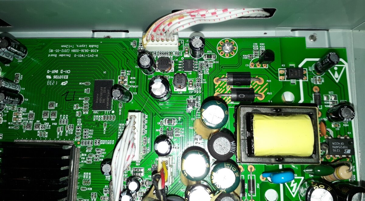
Foto einer bestückten Leiterplatte eines Netzteils
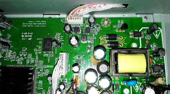
H-DVS-7401-0 Decoder Board 4208-0636-00BH (2012-05-18) Double Layers, t=1.2mm E310728 BC34 BC37 BC54 C5 C15 C20 C21 C22 C23 C24 C25 C26 C27 C28 C29 C30 C31 C32 C33 C34 C35 C36 C37 C38 C39 C40 C41 C42 C43 C44 C45 C46 C47 C48 C49 C50 C51 C52 C53 C54 C55 C56 C57 C58 C59 C60 C61 C62 C63 C64
-
Thread
Dali Dimmer wird rythmisch dunkler und heller.
hier: https://www.leddiretto.it/controllerdimmer-led-4-canali-1224vdc-rgb-rgbw-dali?channable=07acc56d706e00313831312d32393034d7&sku=DLX1224-4CV-DALI&gad_source=1&gad_campaignid=21813135047&gbraid=0AAAAADjh7tr9sxq56PTLVZP_-4KCRErow&gclid=CjwKCAjwspPOBhB9EiwATFbi5KFC2R_NlIUGM9lYCsmiwAn7ya4uCQb50bRlOtFVl64BC2fDakv9ERoC970QAvD_BwE
-
Thread
Spülmaschine nach Überspannungsschaden
Google-Bildersuche kommt man dann auch zu anderen Threads: https://forum.teamhack.de/thread/74462-siemens-sn56p580eu-geschirrsp%C3%BCler-kein-display-keine-funktion/ oder https://forum.teamhack.de/thread/67627-geschirrsp%C3%BCler-siemens-sx66p151eu-b3-keine-funktion/ Die Platine ist zwar nicht 100pro ident
. Dann kann sich da natürlich auch keine Spannung aufbauen. Darauf steht 1GW 9d. 1G scheint für BC847C zu stehen. Hatr das W und das 9d noch was zu sagen?
-
Thread
USB-C CC Pin Beschaltung für 1,5A
aber keine lineare Skala, sondern nur genau 3 Werte sind moeglich (4.7k/12k/36k an 3.3V, oder 10k/22k/56k an 5V, oder aequivalente Stromquellen). Es ist aber AFAICS keine Pflicht, dass ein 5V/3A-Netzteil auch wirklich einen 10k-Widerstand drin hat -- wenn es PD unterstuetzt, koennte es auch 500mA per Widerstand
soll, muss es also beides (CC-Widerstaende und USB-PD) unterstuetzen (und am besten auch noch USB-BC, insbesondere falls jemand ein USB-A-auf-USB-C-Kabel anschliesst).
-
 Bild
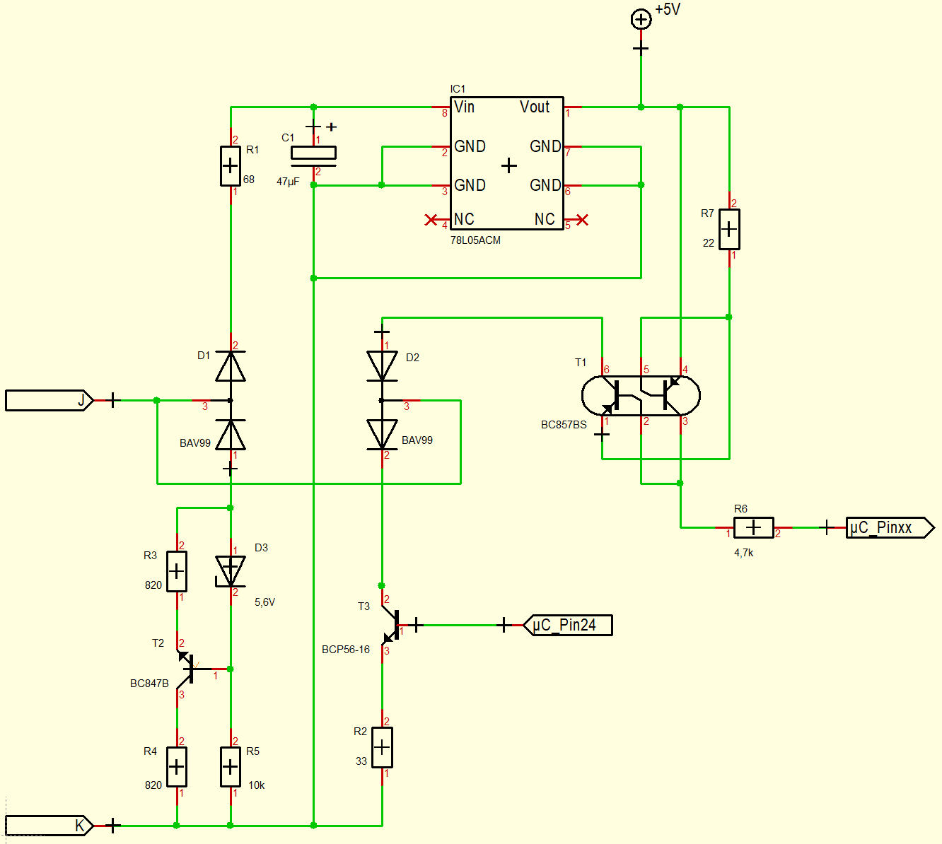
Schaltplan einer Schaltung mit Spannungsregler und Transistoren
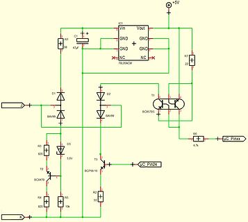
IC1 78L05ACM Vin Vout GND GND GND NC NC +5V C1 47µF R1 68 D1 BAV99 D2 BAV99 T1 BC857BS R7 22 R6 4,7k µC_Pinxx D3 5,6V R3 820 T2 BC847B R4 820 R5 10k T3 BCP56-16 R2 33 µC_Pin24 J K
-
 Bild
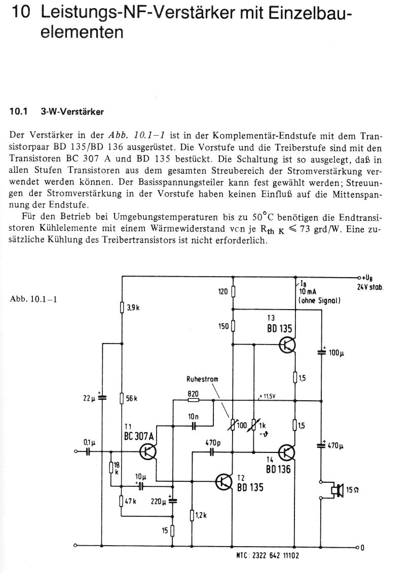
Schaltplan eines 3-W-Leistungsverstärkers
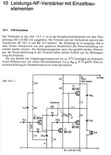
10 Leistungs-NF-Verstärker mit Einzelbauelementen 10.1 3-W-Verstärker BD 135/BD 136 BC 307 A und BD 135 Abb. 10.1-1 3,9 k 22 µ 0,1 µ 18 k 56 k 11 BC 307A 10 µ 47 k 220 µ 1,2 k 15 Ω 0 12 BD 135 14 BD 136 15 Ω 470 µ 1,5 1,5 100 1k 10n 820 150 120 Ia 10 mA +Ub 24V stab. 100 µ 13 BD 135 MIC
-
 Bild
Schaltpläne für L78 Spannungsregler Anwendungen
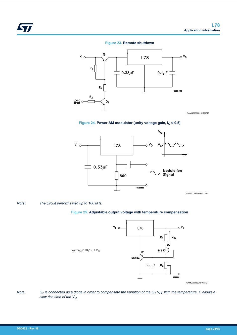
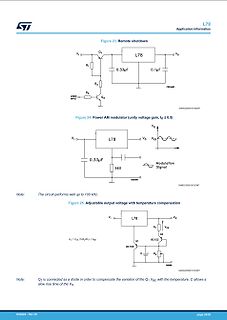
GAMG220920161022MT Figure 24. Power AM modulator (unity voltage gain, lo <= 0.5) VI L78 VO Vxx 0.33µF 56Ω Modulation Signal GAMG220920161023MT Note: The circuit performs well up to 100 kHz. Figure 25. Adjustable output voltage with temperature compensation VI L78 VO R1 Vxx Q2 BC153 C R2 BC153 Q1 GAMG220920161024MT
-
 Bild
Schaltplan eines Transistor-Oszillators
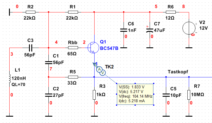
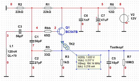
0 R2 2kΩ R1 2kΩ 5 R6 8 12Ω V2 12V C6 1nF C7 47uF 0 0 Q1 BC547B Rbb 2 65Ω 4 C3 56pF 3 C1 56pF 7 L1 120nH QL=70 0 R5 3Ω TK2 V(SS): 1.83 V(dc): 5.217 V V(freq): 104.14 MHz I(dc): 5.218 mA R3 1kΩ C2 27pF 0 Tastkopf C5 10pF R7 10MΩ 0 0
-
Thread
Cursorpositionierung, Farben und Codepage 437 Ausgabe im Linuxterminakl
41 42 43 44 45 46 47 48 49 4a 4b 4c 4d 4e 4f |@ABCDEFGHIJKLMNO| # 00000050 50 51 52 53 54 55 56 57 58 59 5a 5b 5c 5d 5e 5f |PQRSTUVWXYZ[\]^_| # 00000060 60 61 62 63 64 65 66 67 68 69 6a 6b 6c 6d 6e 6f |`abcdefghijklmno| # 00000070 70 71 72 73 74 75 76 77 78 79 7a 7b 7c 7d 7e 7f |pqrstuvwxyz
a7 a8 a9 aa ab ac ad ae af |................| # 000000b0 b0 b1 b2 b3 b4 b5 b6 b7 b8 b9 ba bb bc bd be bf |................| # 000000c0 c0 c1 c2 c3 c4 c5 c6 c7 c8 c9 ca cb cc cd ce cf |................| # 000000d0 d0 d1 d2 d3 d4 d5 d6 d7 d8 d9 da db dc dd de df |................| #
-
Thread
Vor paar Jahren konnten die Burschen kaum laufen Gesperrt
Neuro-Robotics über seinen Werdegang .. sehr beeindruckend: https://www.youtube.com/watch?v=BvqkBX4BcXk
https://www.youtube.com/watch?v=y2PWjZIvjBc "BMW setzt auf humanoide Roboter: Die Strategie hinter Figure, AEON und Physical AI " BWM hat 98%(!) Automatisierungsgrad in der Produktion! Wo rechnet sich weitere Automatisierung? Keine Konkurrenz
-
 Bild
Schaltplan einer Transistorschaltung
J1 Q1 ST901T 2 3 R1 47k 10k R6 Q2 BC547C 1 2 R3 50k R11 470k R2 56k R5 22k C1 100µ C2 10µ D2 130V R4 470k C5 100µ J2

-
Thread
Mini Loopantenne mit NE592N14
Antenna: https://www.mikrocontroller.net/attachment/334874/HF_Active_Loop_Antenna.pdf (ob die beiden BC547 hier eine gute Wahl sind in Bezug auf die obere Grenzfrequenz?) ---------------------- PA0FRI's ACTIVE LOOP ANTENNA - Experiments with various amplifiers.: https://pa0fri.com/Ant/PA0FRI%27s
Package Code > BCX55 BE SOT-89 > https://cdn-reichelt.de/documents/datenblatt/A100/BCX54_55_56.pdf Da würde das Marking anders aussehen.
-
 Bild
Schaltplan einer Spannungsregelung mit LM37T
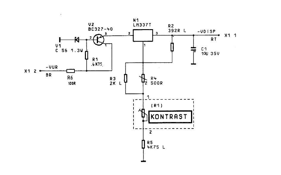
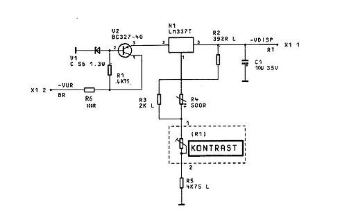
V2 BC327-40 3 2 R2 392R L -VDISP X1 1 N1 LM337T 3 2 1 V1 C 56 1.3W R1 .4K75 2 X1 2 VUR BR R6 100R R3 2K L R4 50R C1 10U 35V (R1) KONTRAST 1 2 R5 4K75 L
-
 Bild
Schaltplan einer Transistorbeschaltung
J1 Q1 ST901T 2 3 R1 47k D1 UF4007 1 R11 470k R2 56k R5 22k D3 UF4007 J2 Q2 BC547C 1 2 3 R3 50k C1 100µ C2 10µ D2 130V R4 470k C3 6.8µ C4 100n C5 100µ