-
Bild
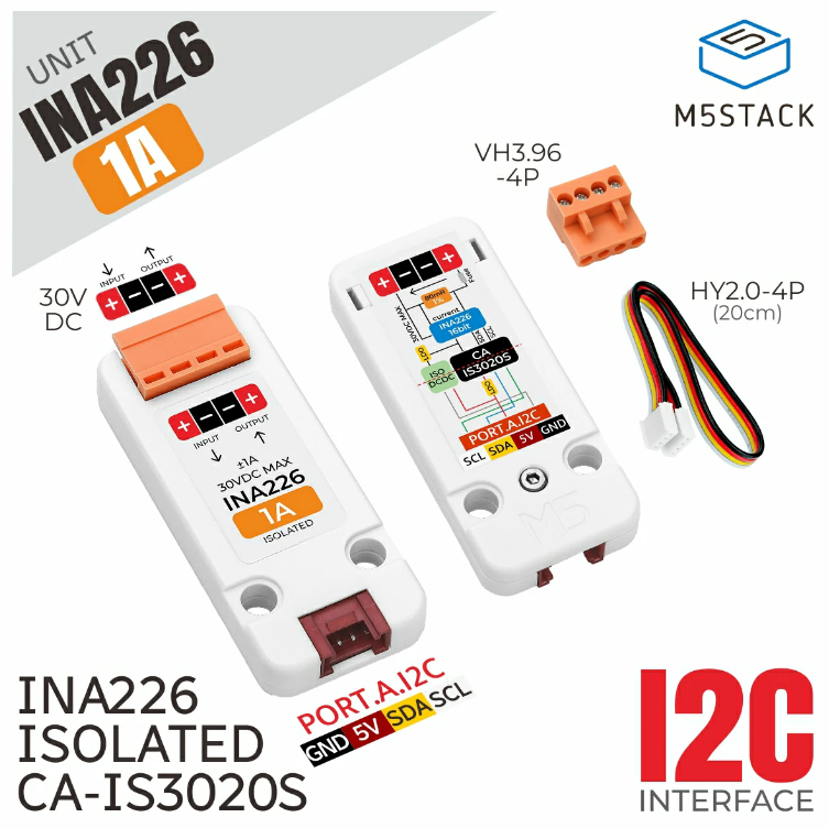
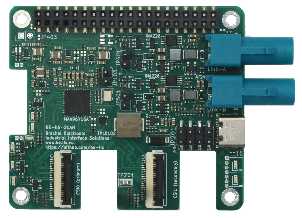
M5Stack INA226 isolierte Strommess-Unit mit Zubehör
UNIT INA226 1A M5STACK VH3.96 -4P INPUT OUTPUT 30V DC INA226 MAX 30VDC CA-IS3020S PORT.A I2C SCL SDA 5V GND HY2.0-4P (20cm) INA226 ISOLATED I2C INTERFACE
in „Neue Bauteile – kleine Relais, nicht durchbrennende LED-Serienschaltungen und Co“ · Analoge Elektronik und Schaltungstechnik · · Fotos
-
Bild
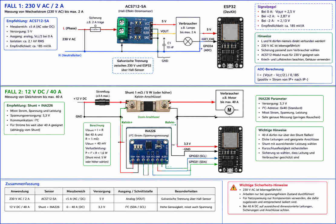
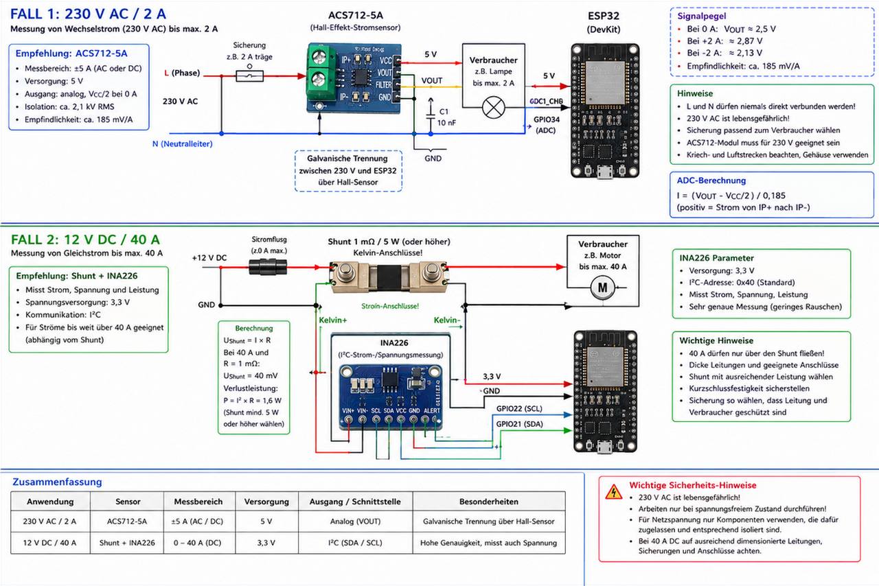
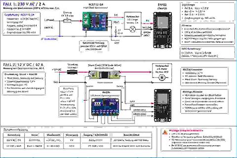
Blockschaltbilder und Zusammenfassung von Strommessungen
DevKit Verbraucher 2,38 Lampen 5 V bis max. 2 A FALL 2: 12 V DC / 40 A Shunt 1 mOhm Kelvin-Anschluss INA226 Verbraucher 40 A Stromfluss GND 12 V DC INA226 Berechnung I = (VOUT - Vcc/2) / 0,185 Zusammenfassung Anwendung Sensor Messbereich Versorgung Ausgang/Schnittstelle Besonderheiten 230 V AC / 2 A ACS712-5A ±5 A (AC/DC) 5 V Analog (VOUT) Galvanische Trennung über Hall-Sensor 12 V DC / 40 A Shunt + INA226 0-40 A (DC) 3,3 V I2C (SDA/SCL) Hohe Genauigkeit, muss auch Spannung
in „Was für eine KI verwendet ihr für Schaltungsentwurf“ · /dev/null · · Diagramme
-
Bild
Blockschaltbilder und Zusammenfassung von zwei Messaufbauten
Verbraucher 230 V AC FALL 2: 12 V DC / 40 A Messung von Gleichstrom (12 V DC) max. 40 A Empfehlung: Shunt + INA226 12 V DC Shunt 10 A Strom 10 A INA226 Verbraucher 12 V DC Zusammenfassung Anwendung Messbereich Verbraucher Ausgang Schaltstelle Umwandlung FALL 1: 230 V AC WESTER 0 - 2 A AC Anleitung FALL 2: 12 V DC 40 A Shunt + INA226 DC PC (SOAR/SC) 40 A (DC) PV Home Automation / Smart Home
in „Was für eine KI verwendet ihr für Schaltungsentwurf“ · /dev/null · · Diagramme
-
Bild
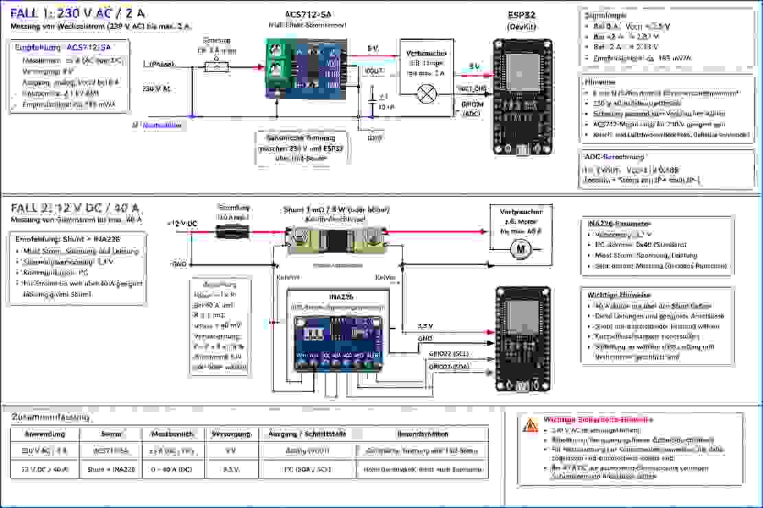
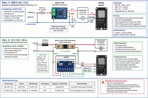
Vergleich zweier Messschaltungen für AC und DC Strom
über Hall-Sensor FALL 2: 12 V DC / 40 A Messung von Gleichstrom bis max. 40 A Empfehlung: Shunt + INA226 +12 V DC GND Shunt 1 mOhm / 5 W (oder höherer) Kelvin-Anschluss Verbraucher z.B. Motor INA226 Parameter Versorgung: 3,3 V I2C-Adresse: 0x40 (Standard) Misst Strom, Spannung, Leistung Berechnung Ushunt
in „Was für eine KI verwendet ihr für Schaltungsentwurf“ · /dev/null · · Diagramme
-
Bild
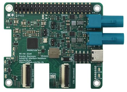
Grüne Leiterplatte mit elektronischen Bauteilen und Steckverbindern
JP403 INA226 Link-A JP401 INA226 AF24 Link-B JP103 JP501 MAX96716A 4.7uH 082618 BE-IIS-2CAM Brechel Electronic Industrial Interface Solutions www.be-iis.eu https://github.com/be-iis JP201 CSI0 (primary) CSI1
in „Realtek-Mikrocontroller mit Bluetooth 7, preiswerter nRF54, GMSL2 für Raspberry Pi uvam“ · Mikrocontroller und Digitale Elektronik · · Platinenfotos
-
PDF
Orion_Rev_3.0__1_.pdf
DB6 51 1 6 9 1 V- 9 DA7 28 INA7 V- 12 12 DB7 52 20 V- 17 ENC DA8 29 INA8 C J31 C76 C75 GND V- R45 DB8 53 C 3 DA9 INA9 100NF 100PF 51 DB9 30 1 LTC6400-20 R44 DA10 54 INA10 DB10 33 2 55 INA11 51 13 DA11 34 RX1 IN MICRO COAXIAL L11
in „Suche Firma die für Privat BGA FPGA reballing macht“ · Markt ·
-
Bild
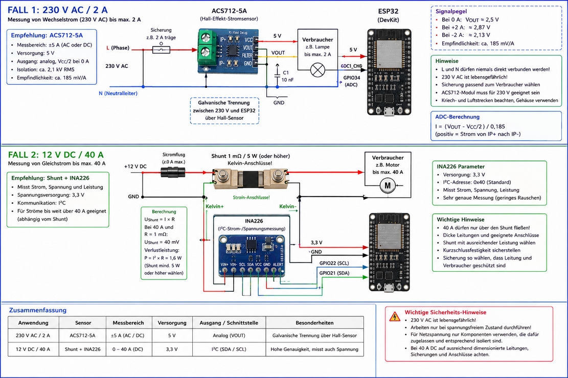
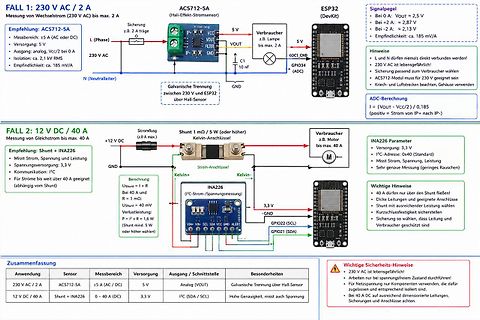
Schaltpläne zur Strommessung mit Hall-Sensor und Shunt
AC5712-SA ESP32 L (Phase) N (Neutralleiter) 230 V AC Verbraucher 5 V max. 2 A FALL 2: 12 V DC / 40 A INA226 Shunt 1 mOhm 12 V DC GND Verbraucher max. 40 A Zusammenfassung Anwendung Sensor Messbereich Versorgung Ausgang / Schnittstelle Besonderheiten
in „Was für eine KI verwendet ihr für Schaltungsentwurf“ · /dev/null · · Schaltpläne
-
PDF
tps63020.pdf
IN= VINA= 3.6 V, A = 25°C 3500 4000 4500 mA High side switch on resistance V = V = 3.6 V 50 mΩ IN INA Low side switch on resistance V IN= VINA= 3.6 V 50 mΩ Quiescent VIN and VINA IOUT = 0 mA, VEN= V IN= VINA= 3.6 25 50 μA q current V, VOUT V OUT = 3.3 V 5 10 μA TPS63021 FB input impedance V EN = HIGH 1 MΩ I Shutdown current V = 0 V, V = V = 3.6 V 0.1 1 μA S EN IN INA CONTROL STAGE Under voltage lockout threshold V INAvoltage decreasing 1.4 1.5 1.6 V UVLO Under voltage lockout hysteresis 200 mV VIL EN, PS/SYNC input low voltage 0.4 V VIH EN, PS/SYNC input high voltage
in „ESP32-H2 will nicht schlafen“ · Mikrocontroller und Digitale Elektronik ·
-
PDF
siplace-s27hm.pdf
1 r t r) rrieb ligrkorew (lo f 3 i g le ta ,liftinr,tran letae mre In )gn (lokc r,tran letaem re :inaC D NG 6 2 l 0 W i x -x11363 00 42P 3 X d i NI 2 a L b r) rrieb ligkfoepp (u )gn (lo kc r,tran leae m re :ineaC n g le ta ,liftin r,tran letaem re In D NG 6 1 i u I x -x11363 00 42P 3 X r t T NI 2 v
in „Siplace 80 Potentialverteiler“ · Mikrocontroller und Digitale Elektronik ·
-
PDF
pm2521ocr.pdf
supplied internal‘y with aconstant-currentsource dependent on the range selected. This currentresults ina pot:ntial difference acrossthe resistorwhich (by Ohim’s Law) isproportional tothe resistancevalue.The resultingvoltagesignal The circuit functions as shown in Fig. 7.age attenuator, the active filterand
in „Pjilips PM2519“ · Markt ·
-
PDF
pm2519ocr.pdf
consist of two complete measurements. clock-edge the logical state of the data signal.The value iskept ina register. During the second period, the data signal isinverted by the ADC interface and on each clock-edge the logicalstate of the input signal, the register iscounted down, Also the input of the A
in „Pjilips PM2519“ · Markt ·