bei hohen Fre abzuheben. Deshalb hat der Spitzenwert Der Umgang mit einem VU-Meter erfor quenzen (max. Wiederga messer eine Integrationszeit von 3 ms bis dert also erhebliche Erfahrung und sollte bespannung bei Sätti 10 ms. eigentlich geschulten Tontechnikern Vor gungsbandfluß) Das VU-Meter zeigt
anzustreben. Typische W erte der gPereesp^nnung (9/16)- 20 V Ipo = 2,9 mA Ausgangsrauschspannung Uv sind: max Signa|.Bngangsspannung UlrTns = 6 V Spannungsverstärkung = 1 Rg 1 kQ 10 kQ 50 kQ 100 kQ Klirrfaktor Übersprechdämpfung kges =0,01% UQr 4 pV 6 pV 8,5 pV <xQ = 70 dB 3,5 pV max. Signal-/Rausch-Abstand
37.5A 0 ~ 19.0A 0 ~ 15.0A 0 ~ 12.7A 0 ~ 9.5A Rated Power 450W 456W 450W 457W 456W Ripple & Noise (Max.) Note.2<1% (mVp-p), according to the rated Output Voltage Output Voltage Adj. Range ±10% Typical adjustment by potentiometer Voltage Tolerance Note.3±1.0% Line Regulation ±0.5% Load Regulation ±0.5%
CARDBOARD (INNER 40 BAG MAX.) The reel pack is applied in SMD LED. The LEDs are packed in cardboard boxes after packaging in normal or anti- electrostatic bags. cardboard boxes will be used to protect the LEDs from mechanical
die Funkwerkstatt, 6. Auflage Frequenzvergleichseinrichtungen mit Elektronenstrahl-Oszillografen S. 105 Frequenzvergleichseinrichtungen mit Ringmodulator S. 105/106 Frequenzvergleichseinrichtungen mit Diodenmiseher S. 107/108 Frequenzvergleichseinrichtungen mit Röhrenmiseher S. 107/108 Frequenz-Vervielfacher
mit Type-C Nennspannung 3.6 V Kapazitaet 6000 mAh / ca. 21.6 Wh Abmessungen ca. 21.8 x 76.8-77 mm Max. kontinuierliche Entladung 10 A USB-C Ladestrom ca. 1.5 A Hersteller-Ladezeit ca. 4 h Standardwert Projektziel 4-5 h Laden; 7-8 h Betrieb Feuerhand Beat Lantern - Masterplan | Stand 14.09.20Seite 7
spezifiziert. Der 3032 war ursprünglich nur für 85° gedacht und dann hat man gemerkt, dass er bei 105° auch noch funktioniert ;) Der RV-3049 hat SPI, der entsprechende I2C-Typ ist der RV-3029. Beide haben einen Nachfolger mit besserem (handlötbarem) Gehäuse: RV-3149-C3 bzw. RV-3129-C3. Beide sind mir
kann > ruhig durch eine kaputte RTC bestraft werden. Dann könnte man auch eine ideale Diode à la MAX40203 einsetzen mit winzigem Eigenverbrauch & Forward-Voltage. Wenn man schon ein PCB designt ;-)
Modelle mit 32 KB (oder mehr) Flash Speicher sind empfohlen. Kommerzielle Umgebungen. Keil µVision (Demo max. 32KB Code/Free für STM32F0/STM32L0): Die sehr komfortable µVison IDE ist neben dem ARM Compiler per Menue auch für einen beliebigen GNU-Compiler konfigurierbar. Damit besteht das 32k-Limit nur noch
auf Debugging von max. 32KB Code limitiert, keine Limitierung beim Complilieren) Rowley Crossworks (Demo 30 Tage unbeschränkt, 150$ für nichtkommerzielle Nutzung, auf GCC basierend). Mir ist nicht klar warum man für diese
nur um eine relative kurze Belastung. Ich meine, > irgendwo auf dem Gerät was gesehen zu haben wie max. 5 Minuten > einschalten und dann 15 oder 20 Minuten Pause/Abkühlen. Also ist das Gerät und der Motor nur für Kurzzeitbelastung mit einer ED von max. 20-25%. Da ist es normal, dass er im Betrieb
Kohlen vertauscht wird. Udo S. schrieb im Beitrag #8095939: > Kurzzeitbelastung mit einer ED von max. 20-25% Das können bei Billigheimern durchaus sogar nur 10% sein innerhalb von 10min... Beim unserem WMF Rührgerät war zusätzlich noch eine 105° Thermosicherung in der Wicklung verbaut. Die hatte
Maximaltemperatur meist mit einer allgemein höheren Stabilität der verwendeten Chemie einhergeht. ### Mill-Max – Pogo-Pins nun vorkonfektioniert. Pogo-Pins aus dem Hause Mill-Max helfen dabei, Steckverbindungen „robuster“ auszuführen. Nun gibt es neue Varianten, die vorkonfektioniert zum Endanwender gelangen
folgenden Abbildungen präsentieren Beispiel-SKUs. 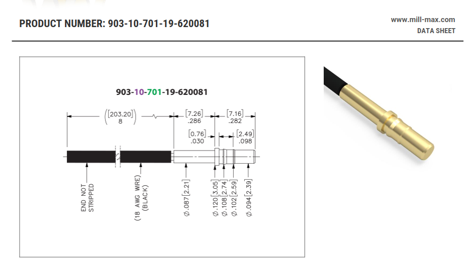 Bildquelle: Mill-Max. 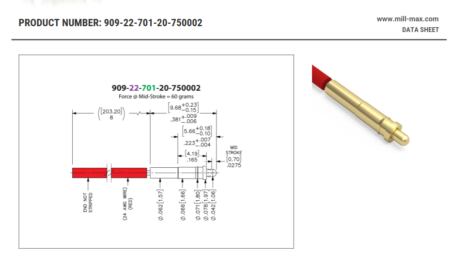 Bildquelle: Mill-Max. ### Chip-Quik IPC0272 / IPC0273 – DFN6-zu-DIP-Adapter. Beim Tanz mit der Steckplatine ist es oft wünschenswert, ein SMD-Bauteil in ein
DEFINES A ZONE WHERE ALL T BODY AND LEAD IRREGULARITIES ARE S ALLOWED. INCHES MILLIMETERS 4 DIM MIN MAX MIN MAX Q A A 0.570 0.620 14.48 15.75 B 0.380 0.405 9.66 10.28 1 2 3 C 0.160 0.190 4.07 4.82 U D 0.025 0.035 0.64 0.88 H F 0.142 0.147 3.61 3.73 G 0.095 0.105 2.42 2.66 K H 0.110 0.155 2.80 3.93 Z J
lockout enter 6.5 7.0 7.5 V VDD_OVP VDD over voltage protection 26.0 27.0 28.5 V Max. Operating 25 V Voltage Current Sense Input Section TLEB LEB time 300 ns Vth_ocp_min Minimum over current threshold 485 500 515 mV Vth_ocp_max Maximum over current threshold 590 mV Vcs_min CS minimum
Symbol Min Typ Max Unit OFF CHARACTERISTICS Collector–Emitter Breakdown Voltage BC237 V 45 — — V (I = 2.0 mA, I = 0) BC238 (BR)CEO 25 — — C B BC239 25 — — Emitter–Base Breakdown Voltage BC237 V(BR)EBO 6.0 — — V (E = 100
Hysteresis V REGOVHYS 30 100 200 mV Oscillator Oscillating Frequency fOSC 450 500 550 kHz R RT00kΩ MAX DUTY1 D MAX1 82 90 98 % V MDT=L, VSYNC=0V MAX DUTY Cycle MAX DUTY2 D MAX2 42 50 58 % V MDT=H, VSYNC=0V MDT Pin Input High Level VIH_MD 0.8 x VREF - V REF+ 0.2 V MDT Pin Input Low Level V -0.3 - 0.2
im Datenblatt keine Angaben zum ESR finden. Hat jemand eine andere Empfehlung? Wichtig sind die max. Betriebs-Std. die der einhalten muß, die Temp. u.v.a. der max. zulässige Rippel-Strom, sonst wir der zu heiß. Der ESR ist da eher nebensächlich.
Beitrag #8089584: > Aber selbst 10000 Stunden sind auch nicht so lange. ist a) min und b) gilt für 105°C - wird mehr durch Arrhenius
ALUMINUM ELECTROLYTIC CAPACITORS Snap-in Terminal Type, 105 °C Standard GU series Withstanding 3000 hours application of rated ripple current at 105°C. Compliant to the RoHS directive (2011/65/EU). GW HighLippleCurrent GU Smaller Low Profile GN GJ Specifications Item Performance Characteristics Category Temperature Range – 40 to + 105°C (16 to 250V) , –25 to +105°C (315 to 450V) Voltage Range Rated 16 to 450V Rated Capacitance Range 47 to 47000µF Capacitance Tolerance ± 20% at 120Hz, 20°C Leakage Current I 3 CV ( A) (After 5 minutes
tuning core as they does not implement core tuning. cod. SBK-50 useful space for the coil = 5,2 mm , max 10 turns , max wire Ø 0,3 mm, max inductance ~ 500 nH useful space for the coil = 5,7 mm , max 4,5 turns , cod. SBK-51 max wire Ø 0,6 mm, max inductance ~ 100 nH useful space price 0,45 € -- 0,40 €
character generator ROM (code 0101) T6963C−0101 is built in as standard. ▯External display memory : 64 KB Max The addresses in display memory of the text area, graphic area and external character generator area are determined by software. ▯Read or Write operations from the CPU do not disturb the display. ▯A
Auf der anderen Seite benötige ich für meinen ESP32 ebenfalls einen Modbus-Adapter, auf dem ein [_MAX485_](https://www.analog.com/media/en/technical-documentation/data-sheets/MAX1487-MAX491.pdf)-Controller für das Modbus-Signal sorgt.
RS485 Treiber sein wie ST485, SN75176BP SN75LBC176, LTC485, SIT3088E SIT3485 SIT3490 SIT65HVD75, MAX487 MAX489E MAX490E, ADM3485
/i key + print information: p/p key + Target weight z/T key Set Setp Min weight value S – min Max weight value S + max Tolerance ranges when values entered via keypad: or Delta min d – d min Delta max d + d max Numeric entry: Numeric keys 0–9 Enter parameters and . + z/T key for “Weight” Target
unit:mm) (unit:mm) 1 6. COIL DATA CHART (AT20 C) ▯ Coil Nominal Nominal Coil Power Pull-In Drop-Out Max-Allowable Coil Voltage Voltage Current Resistance Consumption Voltage Voltage Voltage Sensitivity Code (VDC) (mA) (W –10% (W) (VDC) (VDC) (VDC) SRD 03 03 120 25 abt. 0.36W 75%Max. 10% Min. 120% (High
(2) Thrust washer (3) Axis (4) Deflection pulley (5) Toothed belt (6) Clamping fixture (7) Disks 4 105 4 Gantries Service Manual S-27 HM 4.6 Replacing the deflection unit (00330938-02) 10/2005 US Issue 4.6.4 Installing the deflection unit Æ Insert the new deflection pulley with the two disks into the
External Clock 5 ns Notes: 1. DI pulses narrower thanPWODI (min) will be rejected; pulses wider PWODIt(max) will turn internal DI carrier sense on. 2. DI pulses narrower thanPWKDI (min) will maintain internal DI carrier sense on; pulses widPWKDIa(max) will turn internal DI carrier sense off. 3. CI pulses narrower thanPWOCI (min) will be rejected; pulses wider PWOCIt(max) will turn internal CI carrier sense on. 4. CI pulses narrower thanPWKCI (min) will maintain internal CI carrier sense on; pulses widPWKCIa(max) will turn internal CI carrier sense off. Am79C961 1597
characteristics over recommended operating conditions (unless otherwise noted) PARAMETER TEST MIN TYP MAX UNIT CONDITIONS V = 0 V, See Figure 9 70 115 Total loop delay, driver input to receiverRs) (LOOP1) RSwith 10 kΩ to ground, See Figure 9 105 175 ns output, recessive to dominant RSwith 100 kΩ to ground
2-8 zeigt ein Beispiel. % 1:99 40 1:24 konstanter Durch- 100% schnittsstrom als Prozent 20 1:9 des max. Dauerentlade- 250% 1:1.5 stromes. 1:0 0 Die Daten wurden mit 1% 10% 100% 1000% SL-780 Batterien ermittelt. Pulsamplitude als % des max. Dauerentladestroms 6 Tadiran Batteries Technische Broschüre 2.5
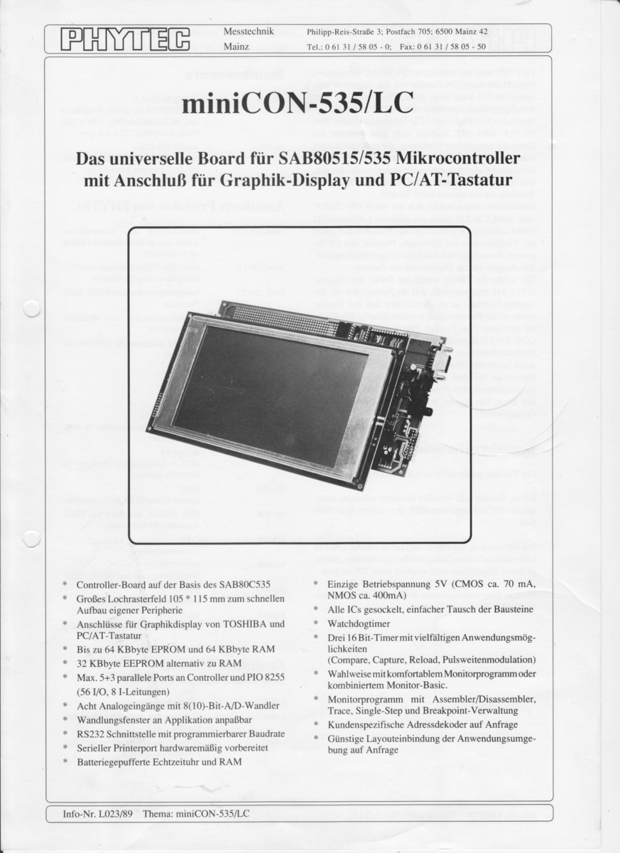
Graphik-Display und PC/AT-Tastatur
* Controller-Board auf der Basis des SAB80C535
* Großes Lochrasterfeld 105 * 115 mm zum schnellen Aufbau eigener Peripherie
* Anschlüsse für Graphikdisplay von TOSHIBA und PC/AT-Tastatur
* Bis zu 64 kByte EEPROM und 64 kByte RAM
* 32 kByte EEPROM alternativ zu RAM
* Max. 5
l H T 10 i40 ∆ a 30 Days e30 Annual Average R 5 20 10 0 0 40 45 50 55 60 65 70 75 80 85 90 95 100 105 110 115 −40 −20 0 20 40 60 80 Temperature (°C) Temperature h (°C) Maximum I vs. T rms h 120% 100% s80% Ir m m 60% a M 40% 20% 0% 40 45 50 55 60 65 70 75 80 85 90 95 100 105 110 115 Temperature Th(°C
× d 187 × 90 × 56 mm, L × l × P Maschenweite 2 mm mesh size 2 mm largeur de mailles 2 mm Nutzlast max. kg max. load kg charge utile max. kg Bestell-Nr. 3082 Code No. 3082 N° réf. 3082 Gerätehalter GH 1 Device holder GH 1 Support d’appareils GH 1 Edelstahl stainless steel acier inox 129 × 117 mm, L × B 129 × 117 mm, l × w 129 × 117 mm, L × I max. Nutzlast1 kg max load 1 kg charge utile max. 1 kg für Glaskolben bis Ø 105 mm for glass flasks dia. 105 mm pour fioles de verre de 105 mm Bestell-Nr. 129 Code No. 129 diamètre N° réf. 129 Folientest-Rahmen
(VS= +36V, V CM = +18V, V O +18V, T = A25℃, unless otherwise noted.) PARAMETER CONDITIONS MIN TYP MAX UNITS INPUT CHARACTERISTICS Input Offset Voltage OS ) 4 120 μV Input Bias CurrentB(I ) 100 pA Input Offset CurrentOSI ) 100 pA Input Voltage Range 0 28.5 V VCM = 0.1V to 34.5V 105 130 Common Mode Rejection
at: www.st.com. Figure 56. HiQUAD-64 mechanical data and package dimensions mm inch DIM. MIN. TYP. MAX. MIN. TYP. MAX. OUTLINE AND MECHANICAL DATA A 3.15 0.124 A1 0 0.25 0 0.010 A2 2.50 2.90 0.10 0.114 A3 0 0.10 0 0.004 b 0.22 0.38 0.008 0.015 c 0.23 0.32 0.009 0.012 D 17.00 17.40 0.669 0.685 D1 (1)
Serie PCG und PCS, größte Can Size ist S mit D=90 und H=235, z.B. PCG 1830µF 450V ESR 1,15mOhm Imax 105A 185Joule PCG 680µF 1100V ESR 1,40mOhm Imax 96A 411J PCS 680µF 1040V 368J PCS 170µF 1800V 275J Die kosten dann auch mehr als 45 Euro. Wima bietet Paroli, z.B. DC-LINK MKP 6: https://www.wima.de
A.P. W. schrieb im Beitrag #8067629: > Die Dinger können lt. DB 2000A max Spitzenstrom, 43A eff. (bei > 10kHz/10°C Eigenerwärmung) > und haben einen ESR von 1mR (10khz). > Wenn man das mit Elkos abdecken will, kommt man wahrscheinlich auch > nicht billiger. Elkos mit
circuit see Fig. 8. Symbol Parameter Conditions 25 °C -40 °C to -40 °C to Unit +85 °C +125 °C Min Typ Max Min Max Min Max 74HC4851 R ON resistance V = V to GND; E = V ON(peak) I CC IL (peak) VCC = 2.0 VSWI= 2 mA - 400 650 - 670 - 700 Ω VCC = 3.0 VSWI≤ 2 mA - 215 330 - 360 - 380 Ω VCC = 3.3 VSWI≤ 2 mA -

 Bild
Bild