-
PDF
edip128-6e.pdf
If an EA 9777-2USB evaluation board is also connected or the display is connected to the PC via a MAX232, this file is automatically burned in the display’s data memory. You can send the created macrofile *.EEP with any other system to the EA eDIP128-6. All programming commands are inside this file,
-
 Bild
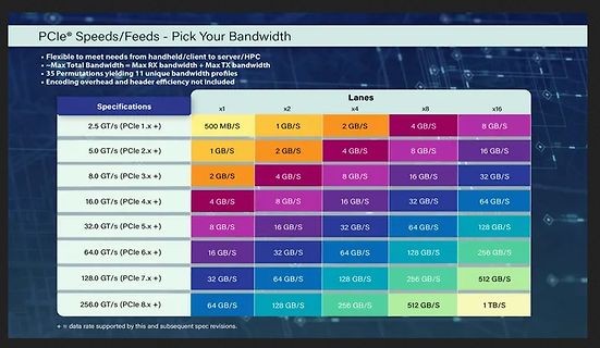
Tabelle der PCIe Bandbreiten nach Generation und Lanes
® Speeds/Feeds - Pick Your Bandwidth • Flexible to meet needs from handheld/client to server/HPC • Max Total Bandwidth = Max RX bandwidth + Max TX bandwidth • 35 Permutations yielding 11 unique bandwidth profiles • Encoding overhead and header efficiency not included Specifications | Lanes x1 | x2 |
in „FCC-Labore auf Gegenseitigkeit, neuer Raspberry Pi-Imager, RISC/V und mehr“ · Mikrocontroller und Digitale Elektronik · · Fotos
-
Datei
VapeDisplayDriver.h
mit Extra-Rand für sauberes Löschen int x_min = x0 - radius - 1; int y_min = y0 - radius - 1; int x_max = x0 + radius + 1; int y_max = y0 + radius + 1; // Clipping auf Display-Grenzen if (x_min < 0) x_min = 0; if (y_min < 0) y_min = 0; if (x_max >= LCD_WIDTH) x_max = LCD_WIDTH - 1; if (y_max >= LCD_HEIGHT
-
Datei
mandel.c
struct { uint8_t r, g, b; } rgb_t; #define ZOOM 2 #define SMOOTH 1 #define graphwidth ((uint16_t) (128 * ZOOM * 3 / 2.5)) #define graphheight ((uint16_t) (128 * ZOOM)) static void putpixel (uint16_t x, uint16_t y, uint8_t r, uint8_t g, uint8_t b); static inline uint32_t rgbfromvalue (uint8_t r, uint8
in „CH32V003, float wirklich langsam?“ · Mikrocontroller und Digitale Elektronik ·
-
Datei
Rep600_fail_blinktgruen.txt
1.761669] ubi0: attached mtd5 (name "ubi", size 52 MiB) [ 1.767208] ubi0: PEB size: 131072 bytes (128 KiB), LEB size: 126976 bytes [ 1.774252] ubi0: min./max. I/O unit sizes: 2048/2048, sub-page size 2048 [ 1.781239] ubi0: VID header offset: 2048 (aligned 2048), data offset: 4096 [ 1.788406] ubi0: good PEBs: 416, bad PEBs: 0, corrupted PEBs: 0 [ 1.794588] ubi0: user volume: 3, internal volumes: 1, max. volumes count: 128 [ 1.802028] ubi0: max/mean erase counter: 1/0, WL threshold: 4096, image sequence number: 1070703713 [ 1.811434] ubi0: available PEBs: 0, total reserved PEBs: 416, PEBs reserved
in „AVM Fritz Repeater 600 - fehlgeschlagenes Firmware Update?!“ · Mikrocontroller und Digitale Elektronik ·
-
PDF
3200.pdf
SY203 Platine Transistoren T1 Si-NPN-Leistungstransistor TO-3 KU607 Kühlkörper T2 Si-NPN-Transistor SF128D Platine BSY55 T3 Si-NPN-Transistor SF128D Platine BSY55 T4 Si-NPN-Transistor SF128D Platine BSY55 T5 Si-NPN-Transistor SF128D Platine BSY55 Sicherungen Si1 Schmelzsicherung 5 mm x 20 mm 0,2 A träge
in „Gefundene neue Serviceanleitung Statron 3200“ · Offtopic ·
-
Datei
SL12NTCs.txt
PART NUMBER RESISTANCE AT 25 °C (R25) TOLERANCE ON R25 VALUE MAX. STEADY-STATE CURRENT UP TO 65 °C MAX. RECOMMENDED ENERGY RATING MAX. VOLTAGE MAX. CAPACITANCE AT 120 V AC RESISTANCE AT 100 % MAX. CURRENT RESISTANCE AT 50 % MAX. CURRENT BODY TEMP. AT 100 % MAX. CURRENT
in „[VS] verschenke 500 Stück NTC Einschaltstrombegrenzer mit ca.14,5 Ohm bei Raumtemperatur“ · Markt ·
-
PDF
RH6016.pdf
mA Fast mode 128 ms Response Time TRE Low power mode (Only 1st 194 ms touch ) (NOTE) VDD=3.0V,operating temperature is 25℃,output without load(unless otherwise specified). NOTE:In low power mode, when a valid touch
in „Funktion Bereichsschalter chinesisches KFZ-Batterieladegerät?“ · Analoge Elektronik und Schaltungstechnik ·
-
PDF
SSD1315.pdf
controller for organic/polymer light emitting diode dot-matrix graphic display system. It consists of 128 segments and 64 commons. This IC is designed for Common Cathode type OLED/PLED panel. SSD1315 displays data directly from its internal 128 x 64 bits Graphic Display Data RAM (GDDRAM). Data/Commands
in „I2C Display einfache Frage“ · Mikrocontroller und Digitale Elektronik ·
-
PDF
ISL88731.PDF
, F is the Acknowledge. The master then sends the higher data byte to be IN,MAX SW written into the desired register. The ISL88731 will respond with switching frequency and I L,MAX is the max DC current in the an Acknowledge. The master then issues a Stop condition, inductor. indicating to the ISL88731 that the current transaction is For VIN,MAX = 20V, VBAT = 12.6V, IBAT,MAX = 4.5A, and complete. Once this transaction completes the ISL88731 will fs= 400kHz, the calculated inductance is 9.3µH. Choosing the begin operating at the new current
in „Chip gesucht“ · Mikrocontroller und Digitale Elektronik ·
-
PDF
T6963C.pdf
. The oscillation frequency does not change with the font selection. ▯Display duty : 1 / 16 to 1 / 128 ▯A 128−word character generator ROM (code 0101) T6963C−0101 is built in as standard. ▯External display memory : 64 KB Max The addresses in display memory of the text area, graphic area and external
in „altes Phytec MCB-51 Monitor/Basic Befehle?“ · Mikrocontroller und Digitale Elektronik ·
-
 Bild
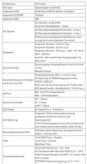
Tabelle mit technischen Spezifikationen eines Mikrocontrollers
Original Epson 16-bit RISC Integriertes ROM 48 kB Flash ROM (für Befehle und Daten) Integriertes EEPROM 128 Byte Integriertes RAM 2kB R/F Wandler CR Oszillator, 24-Bit Zähler Anzahl der Wandlerkanäle: 1 Kanal DC Bias widerstandsbasierte Sensoren: 2 (max.) AC Bias widerstandsbasierte Sensoren: 1 (max.) Referenzstromversorgung
in „Softwareupdates, Mikrocontroller und Neues von Arduino und Raspberry Pi“ · Mikrocontroller und Digitale Elektronik · · Screenshots
-
Datei
usb.c
double words = 64 bytes, so we have 400+64 bytes in total. */ #define USB_RAM 0x40006000 #define EpCtrlMaxLen 64 #define EpCtrlLenId ((1<<15)|(1<<10)) #define EpBulkMaxLen 64 #define EpBulkLenId ((1<<15)|(1<<10)) #define EpIntMaxLen 8 #define EpIntLenId (4<<10) // EP0 = control #define Ep0TxOffset 0 // 64
in „STM32G484 USB CDC Code läuft nur wenn mit <= -O1 kompiliert“ · Mikrocontroller und Digitale Elektronik ·
-
Datei
meindef.h
MAX_S8 INT8_MAX //127 #define MIN_S8 INT8_MIN //-128 #define MAX_S16 INT16_MAX //32767 #define MIN_S16 INT16_MIN //-32768 #define MAX_S24 0x7fffff // 8388607 #define MIN_S24 (-MAX_S24 - 1) //-8388608 #define
in „I2C Display einfache Frage“ · Mikrocontroller und Digitale Elektronik ·
-
PDF
swissbit-U500-USB3-Stick.pdf
and usage level of the flash drive. The given values are for orientation only. 4 Sequential write 128kB simulates a continuous stream recording on a drive which has been preconditioned with a sequential write of the complete drive, Random Write 128KB or 4KB represent data logging applications with large
in „[S] USB Stick für Produktdoku - weniger Speicher, mehr Zuverlässigkeit“ · Markt ·
-
Datei
Messung_der_Spannung_eines_48V_LiFePO4-Akkus_an_seinen_Polklemmen_v1.1.ino
define LED_PIN_GET ((PINB & (1<<LED_PIN)) != 0) uint16_t adc_wert = 0, atomic_adc_wert = 0, adc_wert_max = 0, adc_wert_min = 0; uint16_t tmp_adc_min, tmp_adc_max; // nur für Ausgabe uint8_t anz_ADC_eval = 0; // Anzahl der ADC-Messungen zur Ermittlung der adc-Min-Max-Werte uint8_t entprell_cnt = 0; // Zähler
in „avr adc streuung ausgleichen“ · Mikrocontroller und Digitale Elektronik ·
-
PDF
C22446452.pdf
充电高温 V1=V2=V3=V4=V5=3.5V, 温 DTCH 0.5 1 1.5 s 保 保护延时 RNTC=100k → 10k 护 充电高温 V1=V2=V3=V4=V5=3.5V, DTCHR 128 256 384 ms 解除延时 RNTC=10k → 100k 放电高温 V1=V2=V3=V4=V5=3.5V, 保护延时 DTDH R =100k → 10k 0.5 1 1.5 s NTC 放电高温 D V1=V2=V3=V4=V5=3.5V, 128 256 384 ms 解除延时 TDHR RNTC=10k → 100k 充电低温 T CL V1=V2=V3=V4=V5=3.5V,
in „Einhell elektronik vom 18V Akkupack reparieren?“ · Analoge Elektronik und Schaltungstechnik ·
-
Datei
AvrStudio_c.ini
ROL24 =Keyword ROR24 =Keyword ROL32 =Keyword ROR32 =Keyword ROL64 =Keyword ROR64 =Keyword MIN =Keyword MAX =Keyword ABS =Keyword Align_up =Keyword Align_down =Keyword ROLLOVER =Keyword ROLLUNDER =Keyword AIL =Keyword NIL =Keyword PI =Keyword MAX_U8 =Keyword MAX_U16 =Keyword MAX_U24 =Keyword MAX_U32 =Keyword MAX_U64 =Keyword MIN_S8 =Keyword MAX_S8 =Keyword MIN_S16 =Keyword MAX_S16 =Keyword MIN_S24 =Keyword MAX_S24 =Keyword MIN_S32 =Keyword MAX_S32 =Keyword MIN_S64 =Keyword MAX_S64 =Keyword DLOOP8 =Keyword DLOOP16
in „I2C Display einfache Frage“ · Mikrocontroller und Digitale Elektronik ·
-
PDF
T6963-Application-Note.pdf
Format Size X m TA Y n GA typ. 64x120 6x8 20 8 14H 120 64 14H 14H 1/64 duty 8x8 15 8 0FH 120 64 0FH 0FH 128x128 6x8 21 16 16H 128 128 16H 16H 1/128 duty 8x8 16 16 10H 128 128 10H 10H 64x240 6x8 40 8 28H 240 64 28H 28H 1/64 duty 8x8 30 8 1EH 240 64 1EH 1EH 128x240 6x8 40 16 28H 240 128 28H 28H 1/128 duty 8x8
in „altes Phytec MCB-51 Monitor/Basic Befehle?“ · Mikrocontroller und Digitale Elektronik ·
-
Datei
main.c
runs off the 32.768 kHz ULP oscillator (20 MHz osc stays off). * PWM: TCA0 with PER = 127 -> 256 Hz, 128 levels. While the LED is off the CPU * sits in POWER-DOWN (~0.1 uA, wake on PA1 edge), while on in IDLE so the PWM * keeps running. The PIT (7.8 ms tick, CYC256 of 32.768 kHz) only runs while a * press
in „Lampe Timer deaktivieren“ · Analoge Elektronik und Schaltungstechnik ·
-
PDF
TM56E6422-tenxtechnology.pdf
18Fh.6~0 SVL: DAC output voltage select (reference source can be selected as V CC or VBG 000_0000: 0/128 * reference source 000_0001: 1/128 * reference source … 111_1101: 125/128 * reference source 111_1110: 126/128 * reference source 111_1111: 127/128 * reference source DS-TM56E6422_E 74 Rev 0.9, 2024
in „MCU identifikation/Datenblatt - MC9989A0ZQ“ · Mikrocontroller und Digitale Elektronik ·
-
PDF
lnix-s-a0001298418-1.pdf
pages and configuration screens • Interactive web pages through the use of Java applets • E-mail • 128-, 192-, or 256-bit AES Rijndael encryption (Optional) • EMI tested and compliant • Extended operating temperature: -40 to +85˚ C normal mode -40 to +75˚ C high-performance mode • High-performance processor
in „[V] 1Stück gebrauchtes XPORT-EDGE_Seriell- LAN Modul (12€)“ · Markt ·
-
PDF
lnix-s-a0001298418-1.pdf
pages and configuration screens • Interactive web pages through the use of Java applets • E-mail • 128-, 192-, or 256-bit AES Rijndael encryption (Optional) • EMI tested and compliant • Extended operating temperature: -40 to +85˚ C normal mode -40 to +75˚ C high-performance mode • High-performance processor
in „[V] 1Stück neues Lantronix_XPORT_Seriell- LAN Modul (18€)“ · Markt ·
-
PDF
20240122_Waasner_Katalog.pdf
aus der nachstehenden For details please refer to the following checklist: Bandbreite: min. 10 mm max. 400 mm Strip width: min. 10 mm max. 400 mm Checkliste: Streifenlänge: min. 20 mm max. 3000 mm Strip length: min. 20 mm max. 3000 mm Lochdurchmesser min. 4,5 max. 28 mm Hole diameter: min. 4.5 mm max. 28 mm Bandbreite: min. 10 mm max. 400 mm Strip width: min. 10 mm max. 400 mm AnzahStreifenlänge: enen Lmin. 20 mm ser: max. 3000 mmmax. 3 NumbStrip length: t diamemin. 20 mm max. 3000 mm max. 3 Materialstärke 0,27 / 0,30 / 0,35 / 0,50
in „Was ist aus dem Transduktor geworden?“ · Analoge Elektronik und Schaltungstechnik ·
-
 Bild
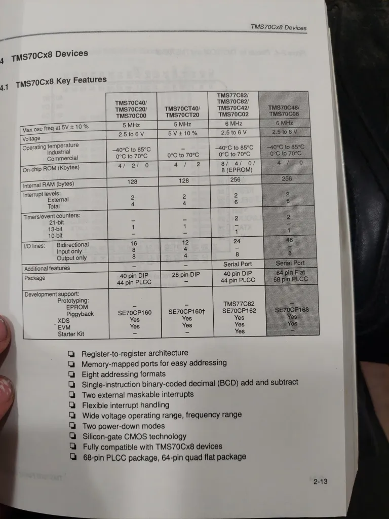
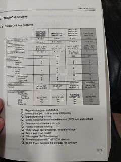
Tabellarische Übersicht der TMS70Cx8 Mikrocontroller-Merkmale
TMS70Cx8 Devices 4.1 TMS70Cx8 Key Features TMS70C40/TMS70C20/TMS70C00 Max osc freq at 5V ± 10% 5 MHz Voltage 2.5 to 6 V Operating temperature Industrial Commercial -40°C to 85°C 0°C to 70°C TMS70CT40/TMS70CT20 5 MHz 5V ± 10% 128 Internal RAM (bytes) 128 256 256 TMS70C82/TMS70C82
in „TMS70C08FNL Datenblatt“ · Mikrocontroller und Digitale Elektronik · · Fotos
-
Datei
bat_sensor_0x0d_analysis.html
125.45, 125.65, 125.86, 126.07, 126.28, 126.49, 126.69, 126.9, 127.11, 127.32, 127.53, 127.73, 127.94, 128.15, 128.36, 128.57, 128.77, 128.98, 129.19, 129.4, 129.61, 129.81, 130.02, 130.23, 130.44, 130.65, 130.85, 131.06, 131.27, 131.48, 131.69, 131.89, 132.1, 132.31, 132.52, 132.73, 132.93, 133.14, 133.35
in „Reverse Engineering eines LIN Bus“ · Mikrocontroller und Digitale Elektronik ·
-
PDF
100807728a.pdf
modes 0–4 ATA data-transfer modes supported Multiword DMA modes 0–2 Ultra DMA modes 0–6 Cache buffer 128 MB Height (mm/in) 7.0 (± 0.2) / 0.276 (± 008) Width (mm/in) 69.85 (± 0.25) / 2.750 (± 0.010) Length (mm/in) 100.35 (+0.20/-0.25) / 3.951 (+0.008/-0.010) Weight (g/lb) max 90 / 0.198 85 / 0.187 Average
in „Komponenten für Low Power Fileserver?“ · PC Hard- und Software ·
-
Datei
fritzbox_7590_log.txt
T1] ubi0: attached mtd4 (name "ubi", size 491 MiB) [ 7.130641][ T1] ubi0: PEB size: 131072 bytes (128 KiB), LEB size: 126976 bytes [ 7.138156][ T1] ubi0: min./max. I/O unit sizes: 2048/2048, sub-page size 2048 [ 7.145620][ T1] ubi0: VID header offset: 2048 (aligned 2048), data offset: 4096 [ 7.153258
in „FritzBox 7590 Boot Loop“ · Mikrocontroller und Digitale Elektronik ·
-
 Bild
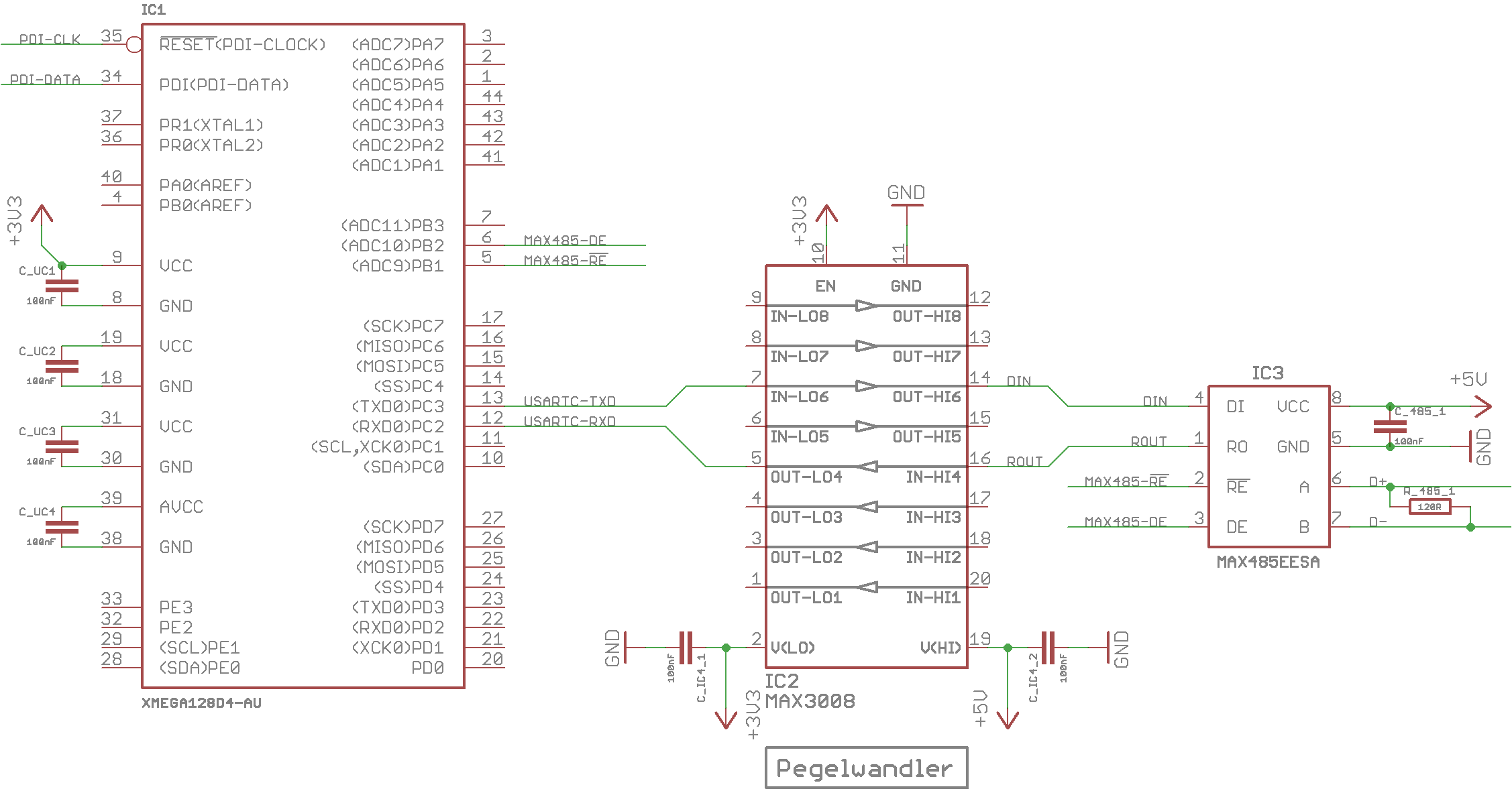
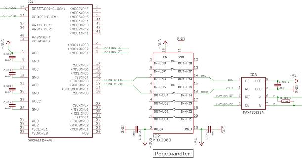
Schaltplan mit Mikrocontroller und Pegelwandler
IC1 XMEGA128D4-AU, IC2 MAX3008, IC3 MAX485EESA, Pegelwandler, 100nF, +3U3, +5U, GND, PDI-DATA, PDI-CLK, RESET, ADC7 bis ADC1, PB3 bis PB0, PC7 bis PC0, PD6 bis PD0, UART, RS485
in „MAX485 - Kommunikations- und Pegelprobleme“ · Mikrocontroller und Digitale Elektronik · · Schaltpläne
-
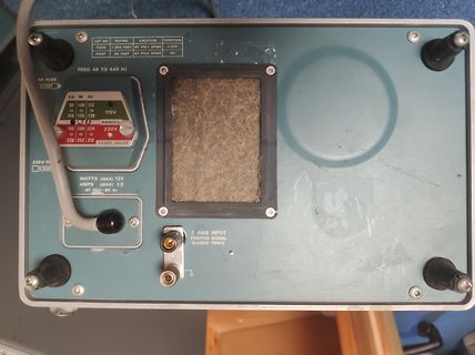
 Bild
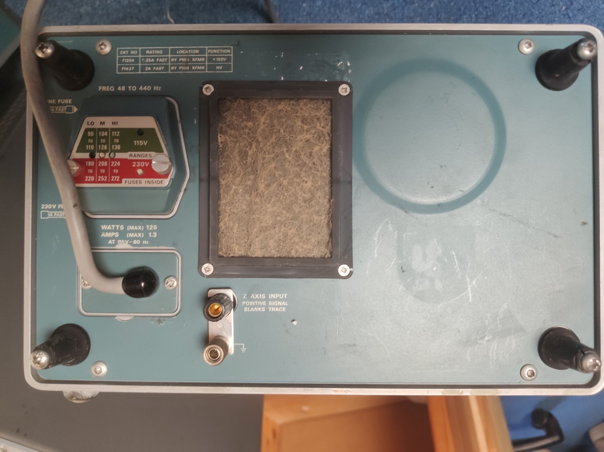
Rückseite eines Messgeräts mit Anschlüssen und Beschriftung
F1204 .25A FAST PW1 XFMR +150V F1437 2A FAST PW8 XFMR HV FREQ 48 TO 440 Hz LO MI HI 90 104 112 110 128 136 115V 230V RANGES 180 208 224 190 252 272 FUSES INSIDE 230V FU FAST WATTS (MAX) 125 AMPS (MAX) 1.3 AT 115V-60 Hz Z AXIS INPUT POSITIVE SIGNAL BLANKS TRACE
in „Biete Verschiedene elektronische Messgeräte HP Tektronix Schomandl WaveteK Empire“ · Markt · · Fotos
-
PDF
NTCLE100E-SERIES_ENG_TDS.pdf
H2 I H 1 L 0 - 40 0 55 85 125 150 P d Tamb(°C) Note • Zero power is considered as measuring power max. 1 % of max. power. PHYSICAL DIMENSIONS FOR RELEVANT TYPE (all dimensions in millimeters) H1 R25VALUE BMAX. d H2 MAX. L P T MAX. MIN. MAX. 3.3 to 220 5.0 0.6 ± 0.06 1.0 4.0 6.0 24 ± 1.5 2.54 4.0
in „Gaggenau Backofen NTC-Luftfühler defekt“ · Haus & Smart Home ·
-
PDF
NTCLE100E-SERIES_ENG_TDS.pdf
H2 I H 1 L 0 - 40 0 55 85 125 150 P d Tamb(°C) Note • Zero power is considered as measuring power max. 1 % of max. power. PHYSICAL DIMENSIONS FOR RELEVANT TYPE (all dimensions in millimeters) H1 R25VALUE BMAX. d H2 MAX. L P T MAX. MIN. MAX. 3.3 to 220 5.0 0.6 ± 0.06 1.0 4.0 6.0 24 ± 1.5 2.54 4.0
in „Defekt bei Sentiotec Sauna/Infrarotkabinen-Steuerung“ · Haus & Smart Home ·
-
PDF
ADC0801_05.pdf
215˚C 0 8 4 A Electrical Characteristics D The following specifications apply fCC 5 VDC , MIN≤TA≤T MAX and fCLK=640 kHz unless otherwise specified. C 0 Parameter Conditions Min Typ Max Units 0 ADC0801: Total Adjusted Error (Note 8) With Full-Scale Adj. ± 14 LSB 5 (See Section 2.5.2) 1 ADC0802: Total
in „Verständnisfrage zum ADC080x (VIN-MIN/DC-Offset)“ · Analoge Elektronik und Schaltungstechnik ·
-
PDF
ET6622.pdf
4bias, 1/8duty, frame frequency is 64Hz ⚫ Max.32×8 patterns, 8 commons, 32 segments ⚫ Built-in internal resistor type bias generator ⚫ 3-wire serial interface ⚫ 8 kinds of time base/WDT selection ⚫ Time base or WDT over flow output ⚫ Built-in LCD
in „Hilfe bei Fehlersuche auf Platine (Displayanzeige schwach)“ · Mikrocontroller und Digitale Elektronik ·
-
PDF
12-13.pdf
Legende der Display-Symbole Legende der Display-Symbole Wirdangezeigt, wennderMAX- oderMINWert abgerufen wird Zeigt denEmpfangdesRFFunksignalsdesAußensensorsan Wirdangezeigt, wenneinRFFunksignal vomAußensensor gesendet wird Zeigt einenniedrigenBatterieladezustanddesAußensensorsan
-
PDF
SAB80C517A.PDF
Data Memory The internal data memory is divided into four physically distinct blocks: – the lower 128 bytes of RAM including four banks containing eight registers each – the upper 128 byte of RAM – the 128 byte special function register area. – a 2 K 8 area which is accessed like external RAM (MOVX-instructions
in „[V] 3 St. Vintage 8051er - Infineon SAB-C517A-4RM- MQFP100 (10€)“ · Markt ·
-
PDF
HD66766R.PDF
Com112 Com176 - Com65 0 1 1 1 0 396 x 120 dots1/120 Duty Com1 - Com120 Com176 - Com57 0 1 1 1 1 396 x 128 dots1/128 Duty Com1 - Com128 Com176 - Com49 1 0 0 0 0 396 x 136 dots1/136 Duty Com1 - Com136 Com176 - Com41 1 0 0 0 1 396 x 144 dots1/144 Duty Com1 - Com144 Com176 - Com33 1 0 0 1 0 396 x 152 dots1/
in „LCD-Modul F51661GNCJU-MLW-AA * Info *“ · Mikrocontroller und Digitale Elektronik ·
-
PDF
LITTELFUSE_TVS_DIODE_1_5KE_DATASHEET.pdf
Lead–free assembly p P -Temperature Min (T s(min) 150°C Ramp-up Critical Zone TLtoPT Pre Heat -Temperature Max (T s(max) 200°C L tL T -Time (min to max) (s ) 60 – 180 secs es(max) t Average ramp up rate (LiquidusTemp (T )A e Ramp-down 3°C/second max ps(min) to peak e Preheat T T S(max)T A Ramp-up Rate 3°C/second max -Temperature (T ) (Liquidus) 217°C 25˚C Reflow A t 25˚C to Peak -Time (min to max) (t ) 60 – 150 seconds Time (t) s PeakTemperature (T ) 260 +0/°C P Time within 5°C of actual peak 20 – 40 seconds Flow
in „230V Schutz mit TVS Diode, Auswahl Diode“ · Analoge Elektronik und Schaltungstechnik ·
-
PDF
rpb_verzeichnis_der_700_bauanleitungen_1971.pdf
Drucktasten-Umschaltung S.113/119* Doppelsuper für 10/80 m S. 120/127* Spitzensuper für 10/80 m (Bausatz) S. 128/139* RPB 45/ 46 UKW-Sender- und Empfänger-Baubuch für Amateure, 7. Auflage 70-cm-Empfänger mit Topfkreis S. 95/99 RPB 108 Amateurfunk-Superhets, 2. Auflage 6-Röhren-Kurzwellen-Superhet, 11Bereiche,
in „Welche Bücher sind im "Radio-Praktiker Bücherei E-Book-Bundle 3 - Ton, Musik & Aufnahme"?“ · Offtopic ·
-
Datei
Poti_16_Stufen.ino
OCR1A_TEILER (F_CPU / T1_VORTEILER / PRO_SEKUNDE) #define ADC_SCHRITTE 1024 // bei 10 Bit #define ADC_MAX (ADC_SCHRITTE-1) #define ADC_KANAL 0 // PC.0 #define POTI_STUFEN 16 #define EINE_STUFE (ADC_SCHRITTE / (POTI_STUFEN - 1)) // 15 Bereiche #define HYS_STUFE (EINE_STUFE / 4) // 1/4 als Hysterese #define
in „Ich möchte aus einer Spannung einen binärcode erzeugen“ · Analoge Elektronik und Schaltungstechnik ·
-
PDF
JDY-40-English.pdf
Default 1 AT+BAUD Baud rate 9600 2 AT+RFID Wireless ID 8899 3 AT+DVID Device ID 1122 4 AT+RFC Channel(128 Channels) 001 5 AT+POWE Transmit power +10db 6 AT+CLSS Type A0 AT instruction instructions In particular, the JDY-40 module sends the AT instruction need to end the symbol \r\n Setting / query - baud
in „AVR Programmübertragung wireless“ · Softwareentwicklung ·
-
PDF
device.pdf
RC28F128J3A ADP-28F128K3-EBG No Need WA28F V6.15 INTEL EEPROM/FLASH/NVRAM RC28F128J3C ADP-28F128K3-EBG No Need WA28F V6.15 INTEL EEPROM/FLASH/NVRAM RC28F128K3C ADP-28F128K3-EBG No Need WA28F V6.15 INTEL EEPROM
-
PDF
TM56M152A-tenxtechnology.pdf
TM56F1552 (TK) TM56F1522 (IO) TM56M152A TM56F1552 (TK) EV board On chip debug TM56F1522 (IO) RAM 336 128 EEPROM 128 X CTK V X SIRC 84 KHz@5V/25℃ 92.8 KHz@5V/25℃ WDT 96ms, 192ms, 768ms,1536ms @5V 91ms, 183ms, 732ms, 1463 ms @5V WKT 12ms,24ms,48ms,96ms @5V 11ms,23ms,46ms,91ms @5V SXT, FXT V X SFR.RDCTL X
in „MCU identifikation/Datenblatt - MC9989A0ZQ“ · Mikrocontroller und Digitale Elektronik ·
-
PDF
LF-SMCJ.pdf
assembly T p P -Temperature Min (Ts(min) 150°C Ramp-up Critical Zone TLtoPT Pre Heat -Temperature Max (T s(max) 200°C ) TL L -Time (min to max) (t) 60 – 180 secs ( s rs(max) Average ramp up rate (LiquidusTemp (T ) a A 3°C/second max eT Ramp-down to peak ms(min) t T Preheat T S(max)T A Ramp-up Rate 3°C/second max Reflow -Temperature (TA) (Liquidus) 217°C 25˚C -Time (min to max) (t) 60 – 150 seconds t 25˚C to Peak s Time (t) PeakTemperature (T P) 260+0/-°C Time within 5°C of actual peak 20 – 40 seconds Temperature
in „Welches Bauteil ist das?“ · Analoge Elektronik und Schaltungstechnik ·
-
PDF
infineon-bsb056n10nn3-g-datasheet-en.pdf
V =6 V, I =15 A GS D Gate resistance RG - 0.5 - - Transconductance gfs 34 69 - S |VDS>2|ID|RDS(on)maxD =30 A Table 5 Dynamic characteristics Parameter Symbol Values Unit Note / Test Condition Min. Typ. Max. Input capacitance Ciss - 4100 5500 pF VGS0 V, V =DS V, f=1 MHz Output capacitance Coss - 750
in „Bauteilsuche Mosfet“ · Analoge Elektronik und Schaltungstechnik ·
-
PDF
SHUTTLE_SPCEL02_DB-DE.pdf
50155 OT1, EN 50121-3-2, MIL-STD-810G RAM/SPEICHER/M.2-Slots ◼ Ein260-PinSO-DIMM-Slot unterstützt max. 32GB DDR4-3200 RAM ◼ Warnung vor heißer Oberfläche: Gefahr von Verbrennungen! ◼ EinM.2-2242/2280M-Slot unterstützt M.2-SSDs mit SATA-Interface OPTIONALES SHUTTLE ZUBEHÖR ◼ EinM.2-2230E-Slot unterstützt
in „[V] Shuttle SPCEL02“ · Markt ·
-
PDF
MC1377.PDF
View Wire: #38 AWG (0.1 m/m) Figure 24. A Prototype Delay Line TDK Sample Number DL122301D–1533 1.26Max 32.0 0.35Max 9.0 *Marking 0.93Max 23.5 0.394〉0.06 10.0〉 1.5 0.2〉 0.04 0.026〉 0.002 5.0〉 1.0 0.65〉 0.33 0.788〉 0.08 20.0〉 2.0 0.8RadiusMax 2.0 Item Specifications Time Delay 400 ns 〉 10% *Marking: Part
in „Problem beim FBAS Signal am Amiga 500“ · Analoge Elektronik und Schaltungstechnik ·
-
Datei
morse_esp32.ino
(rc + dt); barSetup(fsMeasured); } bool audioBegin() { adc_continuous_handle_cfg_t hcfg = {}; hcfg.max_store_buf_size = 16384; // ~400 ms Reserve, falls loop() aufgehalten wird hcfg.conv_frame_size = 256; // 128 Samples pro Frame if (adc_continuous_new_handle(&hcfg, &adcHandle) != ESP_OK) return false
in „Mit KI generierter CW-Decoder für ESP32“ · Mikrocontroller und Digitale Elektronik ·
-
 Bild
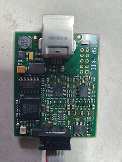
AVRISP mkII Programmiergerät Leiterplatte
AVRISP mkII KYCON 100 M77 61000 HCJ 5A PDIUSB012 74206210 09 bu00811A ATMEL MEGA128 T610A70 355PMZ 625987 MAX4712 EUE
in „Atmel AVRISP MkII, original oder Nachbau?“ · Mikrocontroller und Digitale Elektronik · · Platinenfotos