384 m Not Connected NC 91 m 268 m Receiver Output OUT 91 m 152 m 2 Demodulator Capacitor DEC 768 m 152 m AGC On Control AON 768 m 268 m 3 Power Down PDN 768 m 384 m 4 Positive Receiver Input RFIP 768 m 500 m 5 Negative Receiver Input RFIM 768 m 616 m 5 Not Connected NC 768 m 732 m Power Supply Ground VSS 768 m 848 m Notes: 1) QOM bonding pad is not in use in MAS6180D1 version 2) OUT = VSS when carrier amplitude at maximum; OUT = VDD when carrier amplitude is reduced (modulated) - the output is a current
surface mounting. RoHS-compliant. ELECTRICAL CHARACTERISTICS AT 25 Co Standard Frequency 1) F L 32.768 kHz 2) Load capacitance C L 6.0 / 7.0 / 9.0 / 12.5 pF Frequency tolerance 3) ΔF/F ±20 ppm ΔF/F ±100 ppm Series resistance typ./max. R S 45 / 60 kΩ Motional capacitance typ. C 1 2.25 fF Static capacitance
* keeps running. The PIT (7.8 ms tick, CYC256 of 32.768 kHz) only runs while a * press is handled, for debounce and ramp timing; PA1 irq is masked meanwhile. */ #include <avr/interrupt.h> #include <avr/io.h> #include <avr/sleep.h> #include <stdbool.h> #include
with external components is shown on page 1. Table 3. ELECTRICAL OPERATING CHARACTERISTICS (Min and Max values are over the recommended operating conditions unless specified otherwise. Typical values are at VIN AMB.0 V, T.) Symbol Name Conditions Min Typ Max Units LED−ACC LED Current Accuracy ILEDNOM
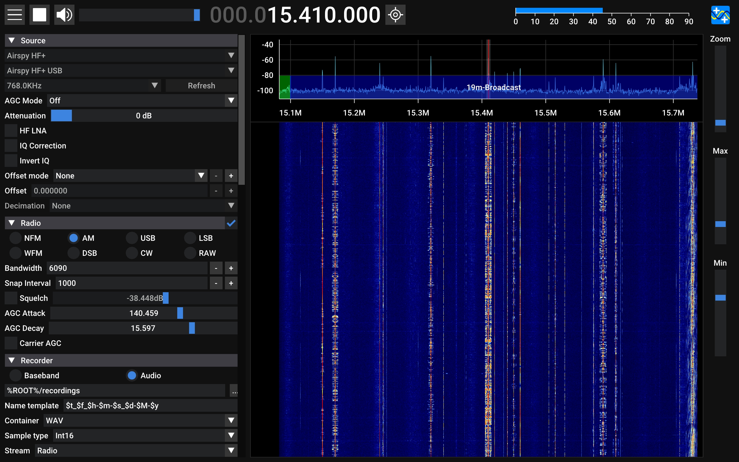
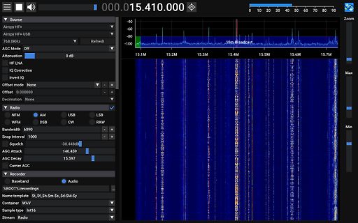
Source Airspy HF+ Airspy HF+ USB 768.0KHz AGC Mode Off Attenuation 0 dB HF LNA IQ Correction Invert IQ Offset mode None Offset 0.000000 Decimation None Radio NFM AM USB LSB WFM DSB CW RAW Bandwidth 6090 Squelch -38.448dB AGC Attack 140.459
parameters M48T58, M48T58Y Table 10. Power down/up AC characteristics (1) Symbol Parameter Min Max Unit tPD E1 or W at VIHor E2 at ILbefore power down 0 µs (2) tF VPFD (max) to VPFD (min) VCC fall time 300 µs (3) M48T58 10 µs tFB VPFD (min) to SS V CC fall time M48T58Y 10 µs t V (min) to V (max) V rise time 10 µs R PFD PFD CC t V to V (min) V rise time 1 µs RB SS PFD CC trec VPFD (max) to inputs recognized 40 200 ms 1. Valid for ambient operating temperaAure: T = 0 toCC0= 4.75 to 5.5 V or 4.5 to 5.5 V (except where noted). 2. V PFD(max) to PFD(min) fall time of lessFthan t may result
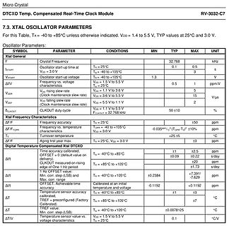
= 1.4 to 5.5 V, TYP at 25°C and 3.0 V.
Oscillator Parameters:
SYMBOL PARAMETER CONDITIONS MIN TYP MAX UNIT
F Xtal Frequency 32.768 kHz
tSTART Oscillator start-up time at TA = 25°C 0.1 0.5 s
VDD = 3.0 V
VSTART Oscillator start-up voltage TA = -40 to +105°C 1.3 V
F frequency vs. voltage characteristics
taken with nominal devices at room temp). 1V8_IN 3V3_IN PARAMETER TEST CONDITIONS UNIT TYP MAX TYP MAX 1 DSSS TX Power = 17.9dBm 92 270 310 6 OFDM TX Power = 17.8dBm 110 170 270 320 54 OFDM TX Power = 15.5dBm 115 215 Continuous TX(1) HT MCS0 TX Power = 17.8dBm 110 270 mA HT MCS7 TX Power = 15.5dBm
× d 187 × 90 × 56 mm, L × l × P Maschenweite 2 mm mesh size 2 mm largeur de mailles 2 mm Nutzlast max. kg max. load kg charge utile max. kg Bestell-Nr. 3082 Code No. 3082 N° réf. 3082 Gerätehalter GH 1 Device holder GH 1 Support d’appareils GH 1 Edelstahl stainless steel acier inox 129 × 117 mm, L × B 129 × 117 mm, l × w 129 × 117 mm, L × I max. Nutzlast1 kg max load 1 kg charge utile max. 1 kg für Glaskolben bis Ø 105 mm for glass flasks dia. 105 mm pour fioles de verre de 105 mm Bestell-Nr. 129 Code No. 129 diamètre N° réf. 129 Folientest-Rahmen
ganze RAM als Grafikspeicher. Die Grafik verfügt, je nach Software-Version, über eine Auflösung von 768x280 oder 768x560 Bildpunkten. Sie wird durch Vektor-Zeichenbefehle unterstützt. Farbgrafik (16 oder 128 frei definierbare Farben pro Bild- punkt) ist mit der Zusatzkarte GRIP-COLOR möglich. Davon abgesehen
Dispersion Penalty (dB) and Total Link Loss (dB). Switch Properties MAC Table Size 2 K Packet Buffer Size 768 kbits Processing Type Store and Forward 2 www.moxa.com Power Parameters Connection 1 removable 4-contact terminal block(s) Input Current 0.29 A (max.) Input Voltage 12/24/48 VDC Redundant dual inputs
vor dem Beenden des Setups gespeichert werden. • Administratorkennwort Min • Administratorkennwort Max • Systemkennwort Min • Systemkennwort Max Password Change Bietet Ihnen die Möglichkeit festzulegen, ob Änderungen an den System- und Festplattenkennwörtern erlaubt sein sollen, wenn ein Administratorkennwort
relative description 0.85 Oct, 2023 3. delete the description about 1/2 Bias and pull-down 4. Modify Max. value of TotalAccuracy and Integral Non-Linearity of ADC Electrical Characteristics 5.Add SOP-14 and change PA2 as PB0 in MSOP-10 and DFN-10 1. Update Electrical Characteristic 0.86 Oct, 2023 2. Modified
EV083(1).docx of JHLin 0.84 Aug, 2023 0.85 Aug, 2023 1. Modify the timing diagram of ADC 1. Modify Max. value of Total Accuracy and Integral Non-Linearity of ADC Electrical Characteristics 2. Add the table of “EEPROM Characteristics” 3. Add subsection for the section of “PWM Trigger ADC” 4. Add description
External Clock 5 ns Notes: 1. DI pulses narrower thanPWODI (min) will be rejected; pulses wider PWODIt(max) will turn internal DI carrier sense on. 2. DI pulses narrower thanPWKDI (min) will maintain internal DI carrier sense on; pulses widPWKDIa(max) will turn internal DI carrier sense off. 3. CI pulses narrower thanPWOCI (min) will be rejected; pulses wider PWOCIt(max) will turn internal CI carrier sense on. 4. CI pulses narrower thanPWKCI (min) will maintain internal CI carrier sense on; pulses widPWKCIa(max) will turn internal CI carrier sense off. Am79C961 1597
the counter is full (therefore the counter is also presettable for the DOWN-phase to get a defined max. DOWN-timing in case of a fault). When the DOWN-phase is ready, the contents of the counter is transferred to the output shiftregister and the AZ-phase is started. The timing of the AZ~phase is done
Control and Laboratory Use European Union Compliance Low Voltage Directive 73/23/EEC, Amended by 93/768/EEC. EN601010-1 – Safety Requirements for Electrical Equipment for Measurement, Control. and Laboratory Use AdditionalCompliance UL3111-1 – Standard for Electrical Measuring and Test Equipment IEC1010

 Bild
 Bild
 Bild
 Bild