-
Thread
DigiTrainer – browserbasierter Simulator des ITT Digi-Trainer 2 (Open Source)
Als nächste Erweiterungen sind unter anderem eine visuelle Anzeige der Schiebeschalter und der der HIGH/LOW-Pegel an den Steckbuchsen, das Speichern und Laden von Schaltungen sowie möglicherweise ein virtueller Signalprüfer vorgesehen. Mich würden besonders eure Meinungen zur technischen Umsetzung
-
 Bild
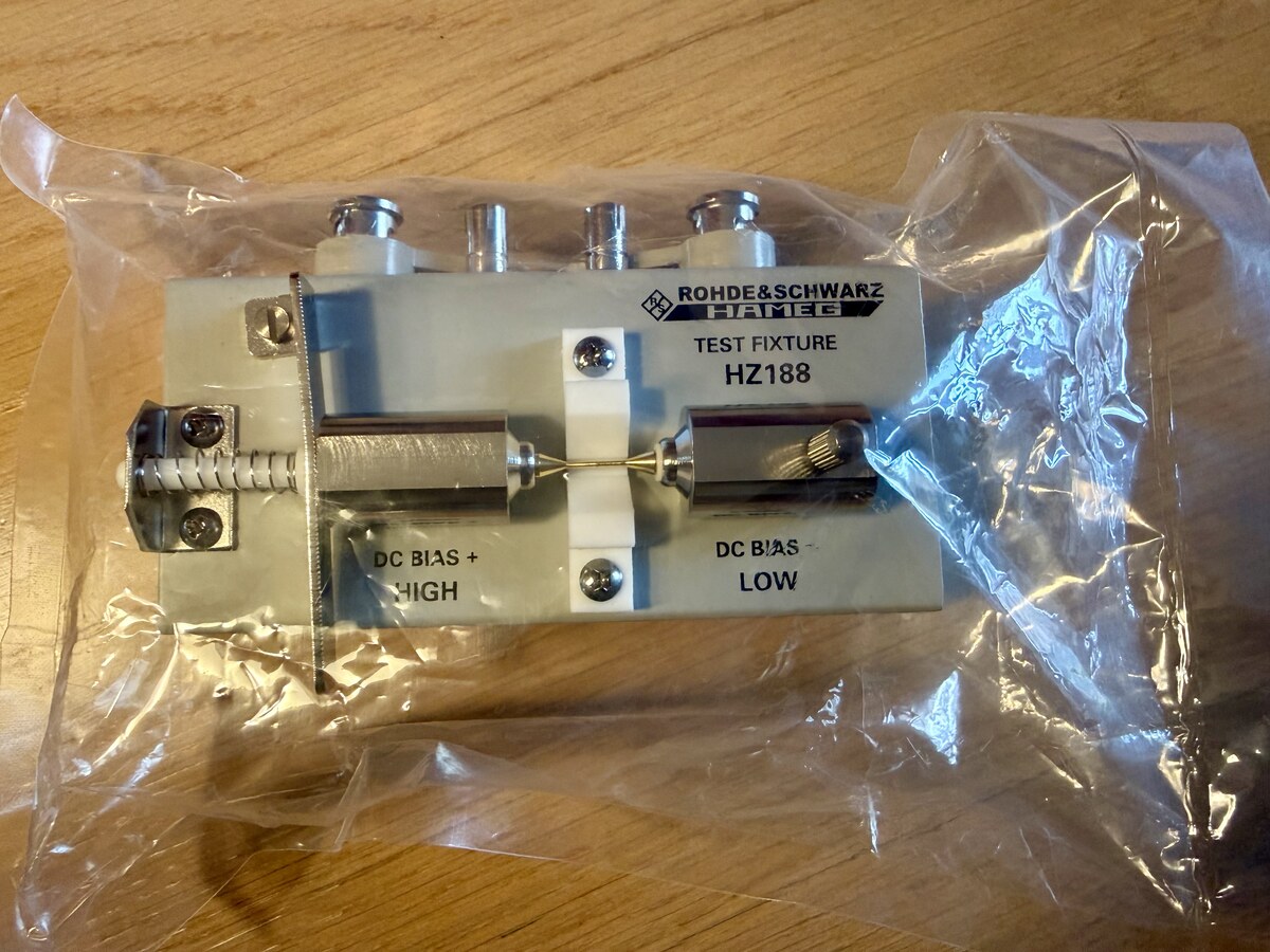
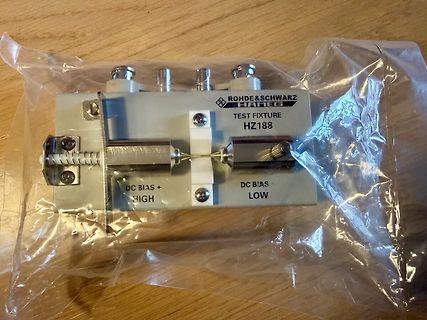
Rohde & Schwarz Hameg Test Fixture HZ188
ROHDE & SCHWARZ HAMEG TEST FIXTURE HZ188 DC BIAS + HIGH DC BIAS - LOW
-
 Bild
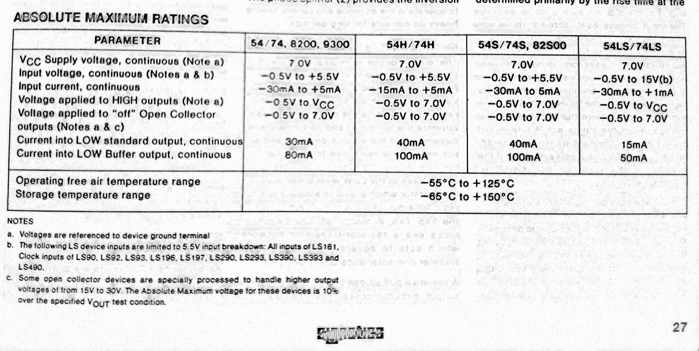
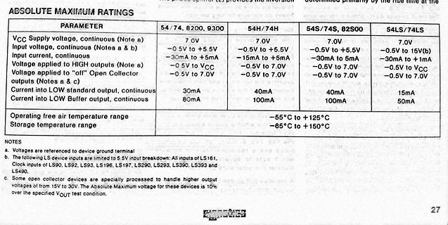
Tabelle der absoluten Maximalwerte eines Datenblatts
Input current, continuous -30mA to +5mA -15mA to +5mA -30mA to 5mA -30mA to +1mA Voltage applied to HIGH outputs (Note a) -0.5V to VCC -0.5V to 7.0V -0.5V to 7.0V -0.5V to VCC Voltage applied to "off" Open Collector outputs (Notes a & c) -0.5V to 7.0V -0.5V to 7.0V -0.5V to 7.0V -0.5V to 7.0V Current into LOW standard output, continuous 30mA 40mA 40mA 15mA Current into LOW Buffer, continuous 80mA 100mA 100mA 50mA Operating free air temperature range -55°C to +125°C Storage temperature range -65°C to +150
-
Thread
Espressif startet Verkauf von Mosaico, Arduino professionalisiert App Lab, Weltraumelektronik uvam
store.mosaico.ai/products/esp-mosaico ### LILYGO T-Halow P4 – ESP32-P4 mit M.2-2280-Interface und WiFi HaLow Das M.2-Interface hat sich im Bereich der Einplatinencomputer mittlerweile als Quasi-Standard etabliert. Nun gibt es im Hause LILYGO eine Entwicklungsplatine, die – wie in der Abbildung gezeigt – über
bekannte Kombination aus ESP32-P4 und ESP32-C6. Hervorzuheben ist, dass außerdem auch ein Wi-Fi-HaLow-Modul auf der Platine verbaut ist. Wer das Produkt käuflich erwerben möchte, kann dies unter anderem auf AliExpress tun. 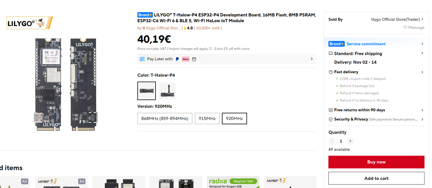 Bildquelle: https://s.click.aliexpress.com
-
 Bild
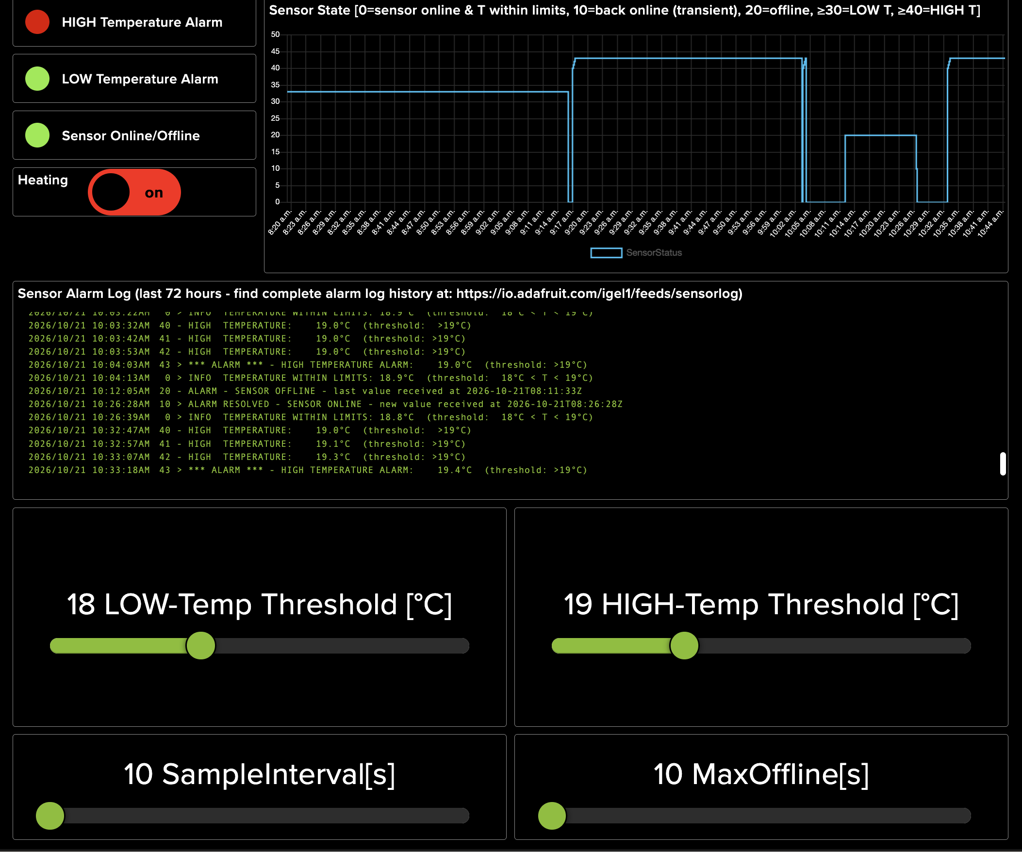
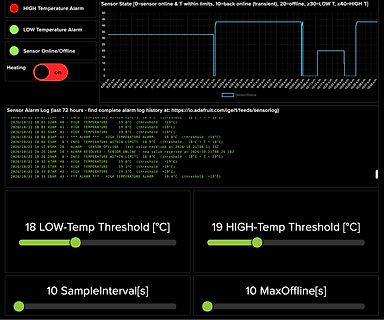
Dashboard einer Temperaturüberwachung mit Graph und Log
HIGH Temperature Alarm LOW Temperature Alarm Sensor Online/Offline Heating on Sensor State [0=sensor online & T within limits, 10=back online (transient), 20=offline, >=30=LOW T, >=40=HIGH T] SensorStatus
-
 Bild
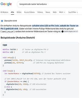
Google-Suchergebnisse für Arduino-Beispielcode
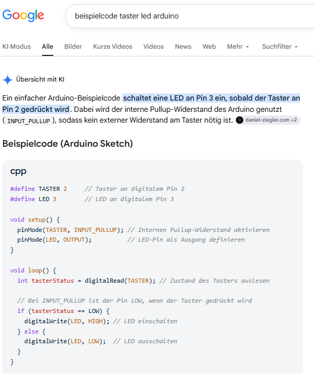
tasterStatus = digitalRead(TASTER); // Zustand des Tasters auslesen // Bei INPUT_PULLUP ist der Pin LOW, wenn der Taster gedrückt wird if (tasterStatus == LOW) { digitalWrite(LED, HIGH); // LED einschalten } else { digitalWrite(LED, LOW); // LED ausschalten }
-
Thread
KiCAD: Erste Gehversuche - bitte um Feedback
Mein Freund soll per Email alarmiert werden, wenn von ihm konfigurierbare Temperaturschwellen (LOW/HIGH) unter-/überschritten werden. - Mein Freund soll informiert werden, wenn sein Sensor keine Daten mehr in die Cloud schickt. - Mein Freund soll mit einem Blick auf die 3 Indikatoren auf
berechnet werden. Und weil so viele fragen, wie man mit einem Heizwiderstand "kühlen" kann, um die LOW-Temperatur-Alarmierung zu testen: - Hier in meinem Zimer sind es aktuell 20 Grad - Also stelle ich die LOW-Schwelle auf 21 Grad und die HIGH-Schwelle auf 22 Grad - Dann Heizwiderstand an -> der
-
 Bild
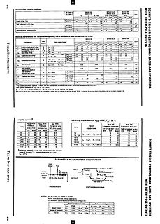
Datenblattabschnitt Texas Instruments Schmitt-Trigger Gates
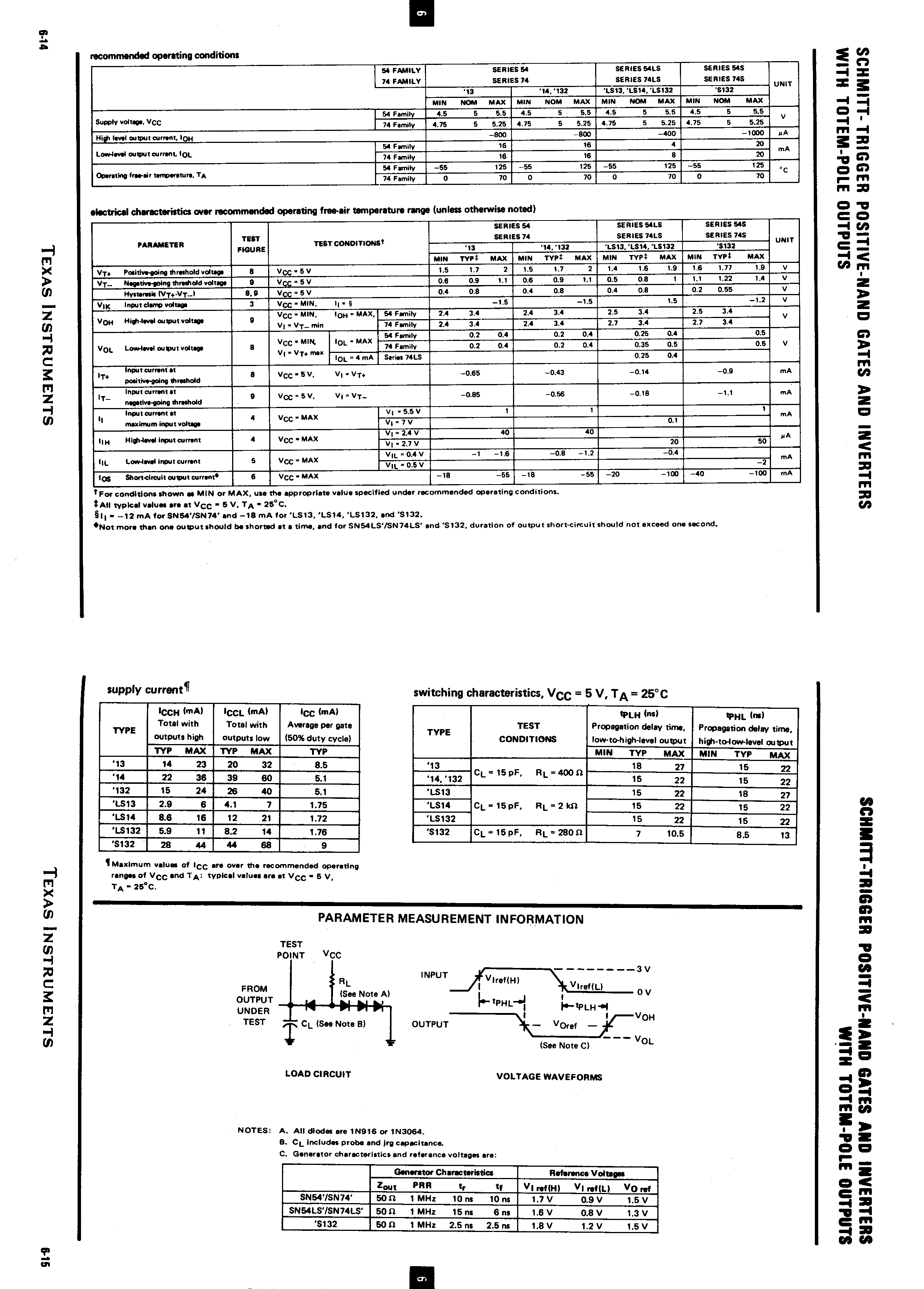
SCHMITT-TRIGGER POSITIVE-NAND GATES AND INVERTERS WITH TOTEM-POLE OUTPUTS parameter supply voltage, VCC high level input current, IHH low level input current, IHL operating free-air temperature, TA electrical characteristics over recommended operating free-air temperature range 74 LS14 74 LS13 74 LS132 74
-
Thread
brauche ein LNB für 3 Endgeräte - Tipps.
x F-Buchse Empfangsystem: QUAD (4 TN) Feedaufnahme: 40 mm Eingangsfrequenz: 10,70 - 11,70 GHz (low), 11,70 - 12,75 GHz (high) Ausgangsfrequenz: 950-2.150 MHz Oszillationsfrequenz: 9,75 GHz (low), 10,6 GHz (high) Polarisation: Entkopplung: > 25 dB Steuerfunktion: 0 kHz (low), 22 kHz (high) Spannungsversorgung
-
 Bild
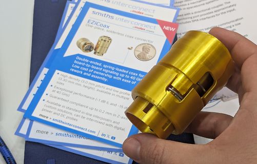
Goldener EZICoax Stecker und Datenblatt
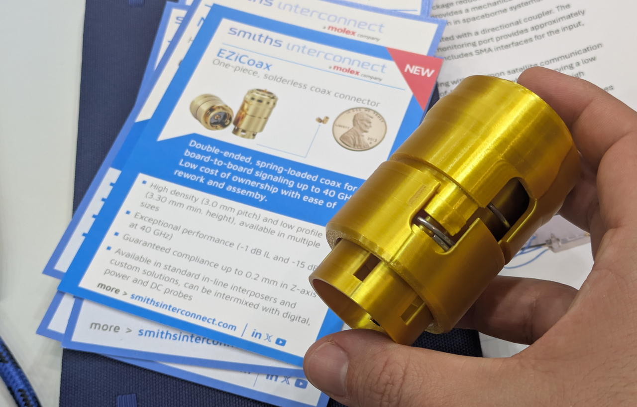
solderless coax connector Double-ended, spring-loaded coax for board-to-board signaling up to 40 GHz High density (3.0 mm pitch) and low profile (3.30 mm min. height), available in multiple sizes Exceptional performance (-1 dB IL and -15 dB return loss at 40 GHz) Guaranteed compliance up to 0.2 mm in Z-axis
-
 Bild
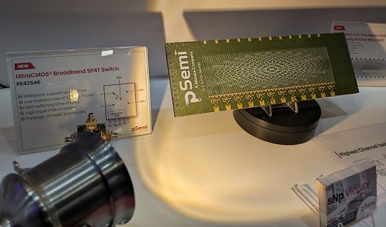
Murata pSemi UltraCMOS Broadband SP4T Switch PE42546
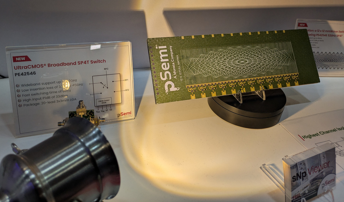
NEW UltraCMOS® Broadband SP4T Switch PE42546 Wideband support up to 6 GHz Low insertion loss of 3 dB @ 6 GHz Fast switching time of bonus High input P1dB of 33 dBm Package: 20-lead 3x3mm LGA pSemi A Murata Company 12 X 12781 MATRIX
-
 Bild
Smartphone-Foto einer Präsentation über Sensor-Innovationen
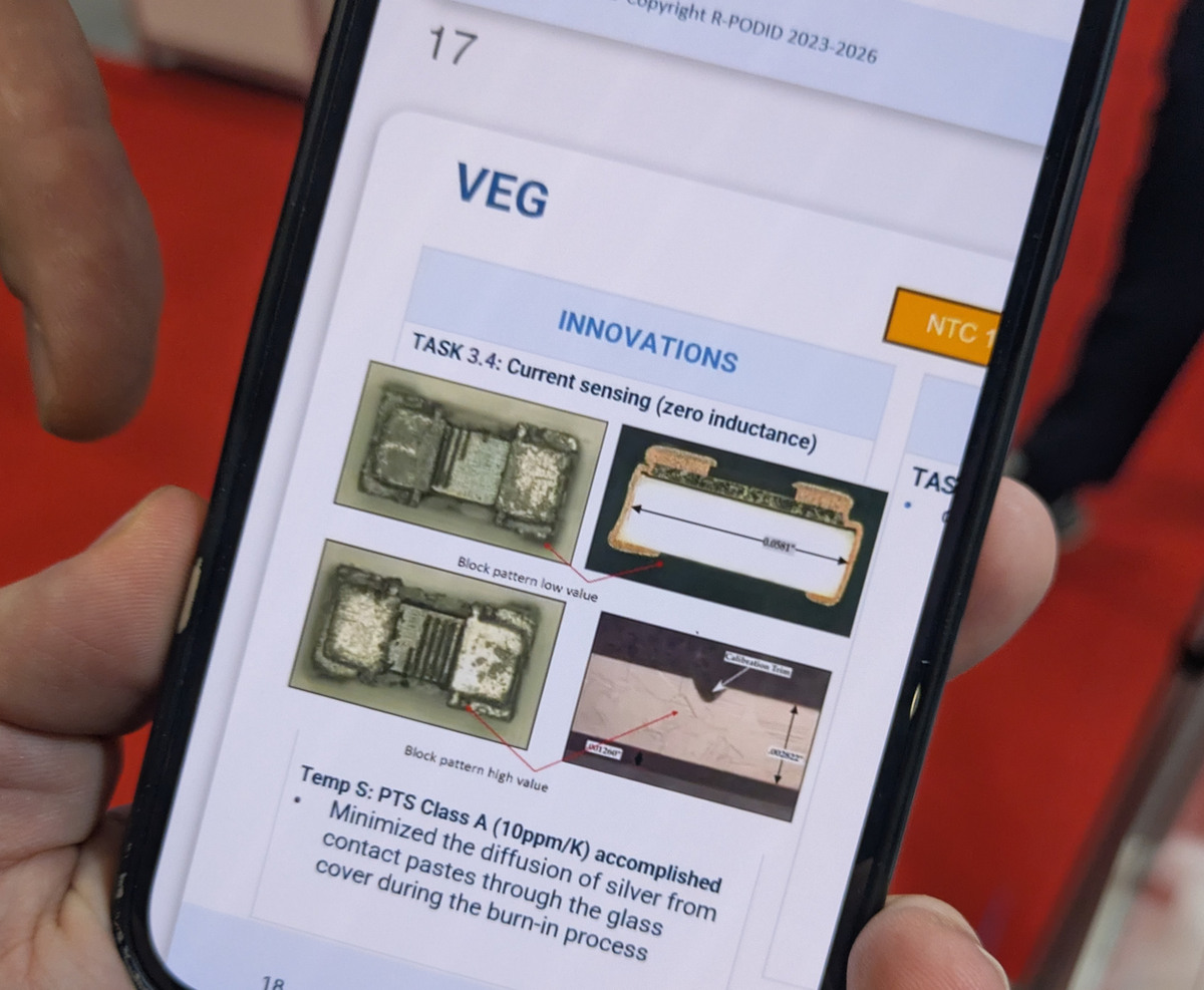
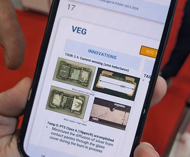
17 VEG INNOVATIONS TASK 3.4: Current sensing (zero inductance) Block pattern low value Block pattern high value Temp S: PTS Class A (10ppm/K) accomplished Minimized the diffusion of silver from contact pastes through the glass cover during the burn-in process
-
 Bild
Datenblatt eines Vishay High Power Widerstands
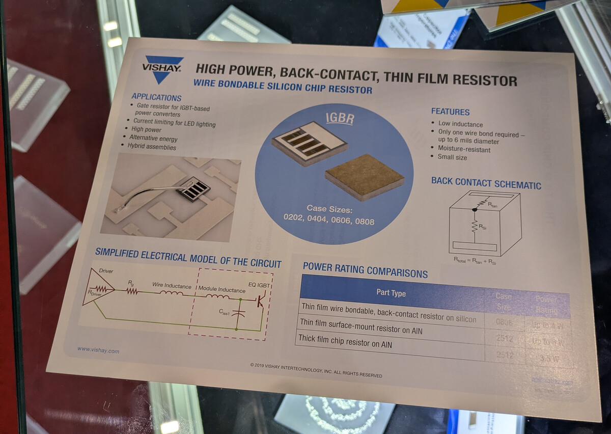
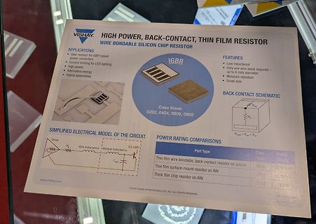
VISHAY HIGH POWER, BACK-CONTACT, THIN FILM RESISTOR WIRE BONDABLE SILICON CHIP RESISTOR APPLICATIONS Gate resistor for IGBT-based power converters Current limiting for LED lighting High power Alternative energy Hybrid assemblies FEATURES Low inductance Only one wire bond required – up to 6 mils diameter Moisture-resistant Small size Case Sizes: 0202, 0404, 0606, 0808 BACK CONTACT SCHEMATIC SIMPLIFIED ELECTRICAL MODEL OF THE CIRCUIT POWER
-
Thread
[VS] verschenke Taststift
10100011010000101001100101000110111001000100101010111001011011001100110100010010111001010000101 1 bedeutet schwarz, im Oszillogramm low 0 bedeutet weiß, im Oszillogramm high
gleichmäßig genug gezogen, ein > kurzer Versuch das Oszillogramm optisch auszuwerten in dem man die "Low" > Stellen schwarz ausfüllt und noch ein wenig nachbessert hatte bei mir > nicht funktioniert. Vielleicht die falsche Hoehe im Oszillogramm gewaehlt, hier hat es geklappt (gescannt mit "Binary
-
Thread
FPGA verrechnet sich sporadisch
agiert. Auch der Kompressor springt bei 70% teilweise verfrüht an. Es wird also irgendwann ein Bit high, obwohl es noch low sein müsste. Ich nehme an, daß es ein Bit im Bereich (21 .. 20) ist, daß unzulässig mit aufaddiert wird. Leider kann ich es nicht testen, weil ich keinen debug core dort einsetzen
-
 Bild
Technische Spezifikationen eines Messgeräts
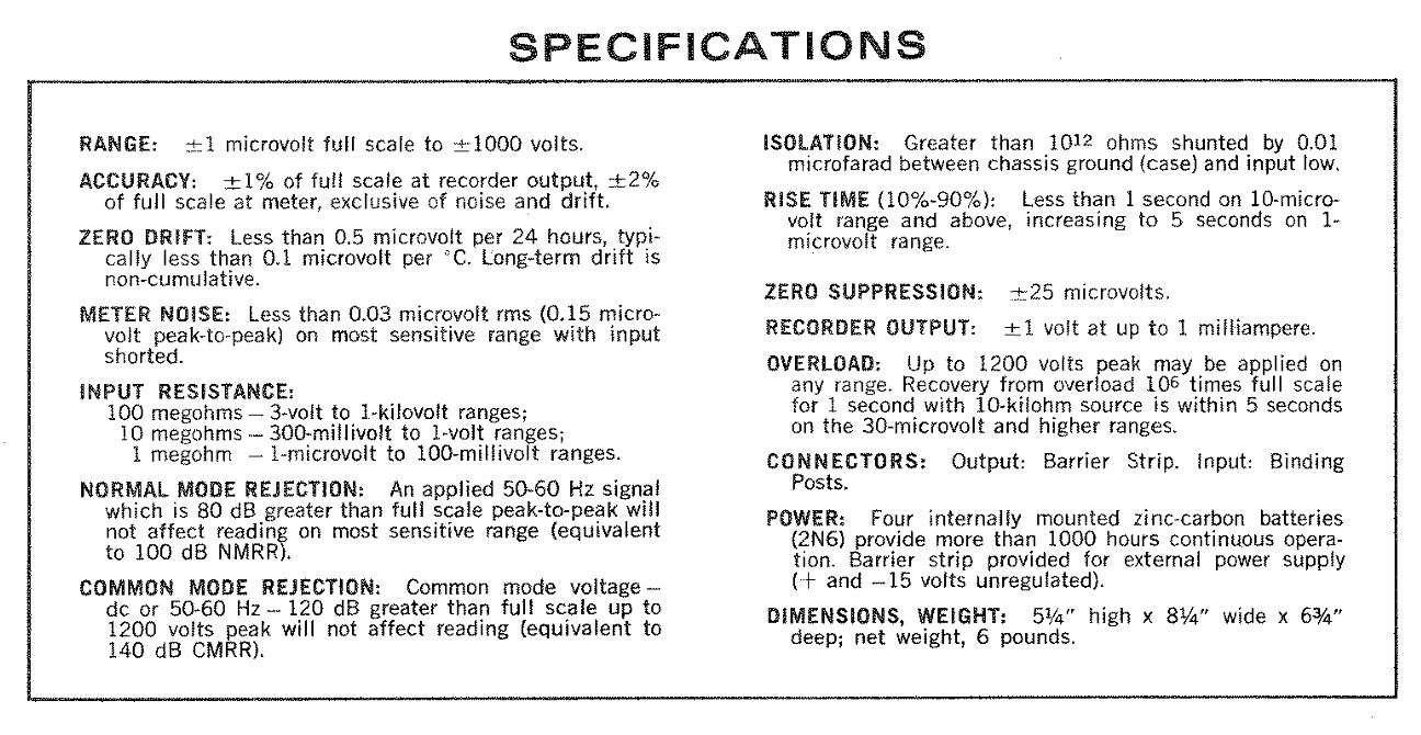
any range. Recovery from overload 10^6 times full scale within 5 seconds on the 30-microvolt and higher ranges. CONNECTORS: Output: Barrier Strip. Input: Binding Posts. POWER: Four internally mounted zinc-carbon batteries (2N6) provide more than 1000 hours continuous operation. Barrier strip provided for external power supply (+ and - 15 volts unregulated). DIMENSIONS, WEIGHT: 5 1/4" high x 8 1/4" wide x 6 3/4" deep; net weight, 6 pounds.

-
Thread
Problem beim Hochladen zum Arduino Nano
, TXD und RESET pins wirklich frei liegen. Im "Nichts tun" Zustand müssen die erwähnten Pins alle High-Pegel haben. Auch würde ich nachprüfen ob zufällig eine Verbindung von den erwähnten zu anderen Pins existiert. Es könnte durchaus sein, daß zwar die Lötstellen einwandfrei sind, aber die Bord Ätzfehler
Host wird der RTS Ausgang vom Host während einer gültigen Verbindung (Terminal, AVRDude) permant auf Low Pegel gehalten. Das bewirkt während der Transition von High auf Low, dass die RESET Leitung des AVR einen kurzen Impuls erfährt und einen Reset Startup durchführt. In anderen Worten, der Nano reagiert
-
Thread
Originaler TI MAX3232EIDR mit 21mA Ruhestrom?
Driver Two drivers interface standard logic level to RS232 levels. __Both DIN inputs must be valid high or low.__
-
 Bild
Schaltplan und Foto eines Relais-Moduls
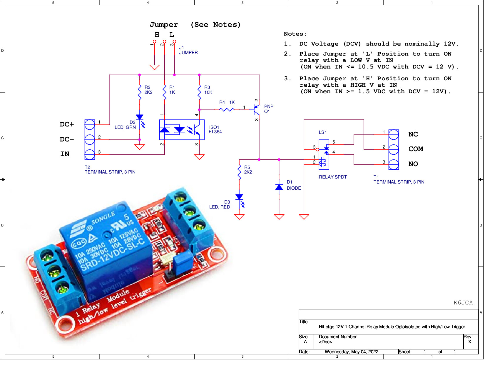
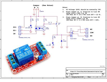
D3 LED, RED D1 DIODE SONGLE SRD-12VDC-SL-C 10A 250VAC 10A 125VAC 10A 30VDC 10A 28VDC Relay Module high/low level trigger
-
 Bild
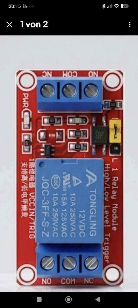
Rotes Relais-Modul mit zwei Schraubklemmen
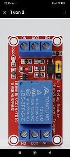
20:15 29 NC COM NO PWR L1 Relay Module High/Low Level Trigger JQC-3FF-S-Z TONGING 12VDC 10A 250VAC 15A 125VAC NO COM NC
-
Thread
Yamaha NS-SW300 kommt nicht aus Standby
Servicehandbuch sollte er ab 100Hz 8mV am LFE Eingang wach werden in der Auto-Standby-Einstellung "high". (Bei "low" braucht es ein paar mV mehr, der genaue Wert ist mir nicht bekannt) Ich nutze nun schon ein Y-Kabel am Normalen Input. Doch die +3dB retten es nicht. Der Sub wird einfach viel zu spät wach
und der Ausgang IC1/3 low, die rote LED leuchtet über Q1 und R32 (2k7). Hast Du ein Oszi? Systematisch messen und suchen! Nebenbei: Q46 wird reverse betrieben. Das hatten wir vor kurzem: Siehe https://www.mikrocontroller.net
-
Thread
Wer kennt einen PC mit 2 Printerports?
Falle drei simultaner Frickelports mindestens einer auf Interruptbetrieb verzichten. *) Active-High-Interrupts, mit "totem-pole"-Treibern angesteuert ... das ist ausgesprochen dämlich. Praktisch alle anderen Systeme haben Active-Low-Interrupts verwendet, und die mit Open-Collector- bzw. Open-Drain-Treibern
langen Slotbleche kann man abschrauben Es gehören sogar kurze zum Lieferumfang ("Packungsinhalt 2x Low Profile Blende")...
-
Thread
AI-Spielplatine ESP-Mosaico, neue Messtechnik, RPi-Preiserhöhung und mehr
suppression is achieved across a wide frequency range, enabling accurate and reliable results in high-precision receiver testing and sensitive measurements. [/c] Interessant ist außerdem, dass das Gerät eine externe Maus und eine externe Tastatur unterstützt – weitere Informationen finden sich unter
industrial cybersecurity requirements such as IEC 62443 and the Cyber Resilience Act (CRA). To address high-speed connectivity and industrial control requirements, the new devices provide a rich set of peripheral interfaces, including Gigabit Ethernet, USB 2.0 High-Speed Host/Device, SD 3.0/eMMC, CAN FD,
-
Thread
USB RS485 Adapter mit Heizungssteuerung verbinden
supply for the isolated terminal* *Onboard unibody digital isolation, allows signal isolation, high reliability, strong anti-interference, low power consumption"* Muss ich etwas beachten, damit ganz sicher nichts an der Heizungssteuerung kaputt geht? Oder kann ich gefahrlos über eine Doppelader
steht auch etwas zur Isolation, [...]: > "Safer Isolated Design > [...] allows signal isolation, high > reliability, strong anti-interference, low power consumption" Das übliche China-Marketing-Geblubber. Alles maximal schwammig, ohne jegliche Aussagekraft. Christian schrieb im Beitrag #8101265
-
Thread
ATMega 48, Pinchange Interrupt, ASM
************************************************************************** start: ldi temp, low(ramend) out spl, temp ldi temp, high(ramend) out sph, temp ;PortB; B2 = Interruptpin; PortC; C5 = LED ldi temp, 0x00 ;PortB auf Eingang out DDRB, temp
schon Spannung, dann bitte mal anschauen welche Spannungen im gültigen Toleranzbereich der Pegel "high" und "low" liegen da es ja gerade bei dieser Sache um definierte Zustände und den Wechsel zwischen diesen geht. https://de.wikipedia.org/wiki/Logikpegel https://www.google.com/search?q=avr+logikpegel
-
Artikel
Linksammlung
based on Free Software tools and the code is distributed under GNU GPL. (Atmega16) USB PWM Generator Low Cost PWM Generator, über USB Programmierbar. 1Hz - 120khz Duty Cycle 1 - 99 %. Electronics Hub - Huge collection of electronics projects, free electronics circuits and other technical information is
Bedienungsanleitungen / Manuals. BAMA Archiv Big-List.com - This is a directory of over 600 dealers in used high technology equipment. Most deal in used electronic test equipment or semiconductor production equipment. Included are dealers in related high technology items, rental companies, equipment auction sites
-
Thread
Neue Bauteile: vom Radar bis zum Widerstand
elevated resistive element reduces thermal stress on the PCB, while the all-metal construction provides low inductance, high pulse capability, and an operating range of -55°C to +170°C. The HCSK1216 is available in 0.3, 0.5, 1, and 2 milliohm values, with tolerances as low as 1% and TCR as low as 50 ppm
Detail beschrieben – mit seinem extrem geringen Eigen-Strombedarf positiv auffällt: [c] • Ultra-low power consumption: ~7 nA (at VDD = 1.55 V; TAmb = 25 °C; fs = 1.2 Hz) • Supply voltage range: 1.1 V to 3.6 V • Capable of high output current to drive loads directly • Operating point: ±1.0 mT •
-
 Bild
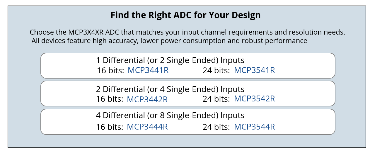
Auswahlhilfe für MCP3X4XR ADC Modelle
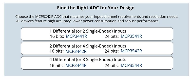
MCP3X4XR ADC that matches your input channel requirements and resolution needs. All devices feature high accuracy, lower power consumption and robust performance 1 Differential (or 2 Single-Ended) Inputs 16 bits: MCP3441R 24 bits: MCP3541R 2 Differential (or 4 Single-Ended) Inputs 16 bits: MCP3442R 24
-
 Bild
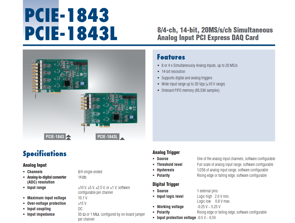
Datenblatt einer PCIe-DAQ-Karte
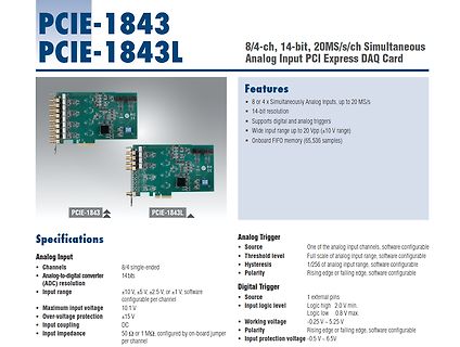
falling edge, software configurable Digital Trigger Source 1 external pins Input logic level Logic high 2.0 V min, Logic low 0.8 V max. Working voltage -0.25 V ~ 5.25 V Polarity Rising edge or falling edge, software configurable Input protection voltage -0.5 V ~ 6.5 V
-
 Bild
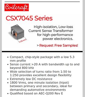
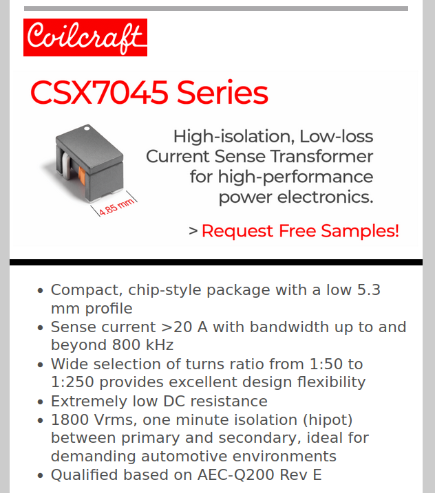
Produktblatt Coilcraft CSX7045 Stromwandler
Coilcraft CSX7045 Series High-isolation, Low-loss Current Sense Transformer for high-performance power electronics. > Request Free Samples! • Compact, chip-style package with a low 5.3 mm profile • Sense current >20 A with bandwidth