-
Datei
main.c
16000000UL #include <stdint.h> // Header File für Datentypen (uint8_t, etc.) #include <stdlib.h> #include <avr/io.h> // Header File für IO Ports #include <avr/interrupt.h> // Header File Interrupt Vektoren #include <avr/pgmspace.h> // Markos für PGM Space // INCLUDES für UART #include "uart.h" #define ANZAHL1
in „µC rechnet falsch oder ich finde den Fehler nicht“ · Mikrocontroller und Digitale Elektronik ·
-
Datei
main.c
16000000UL #include <stdint.h> // Header File für Datentypen (uint8_t, etc.) #include <stdlib.h> #include <avr/io.h> // Header File für IO Ports #include <avr/interrupt.h> // Header File Interrupt Vektoren #include <avr/pgmspace.h> // Markos für PGM Space // INCLUDES für UART #include "uart.h" #define ANZAHL1
in „µC rechnet falsch oder ich finde den Fehler nicht“ · Mikrocontroller und Digitale Elektronik ·
-
PDF
Schematic_Atmega32U2_Ult.GPS_NOR-Flash_Sheet_1_20200330171408.pdf
pF 2 PC0(XTAL2) (PCINT7/OC.0A/OC.1C)PB7 21 AVR ISP QUARZ 16MHZ 6 C2 (OC.0B/INT0)PD0 7 (AIN0/INT1)PD1 Kond. 22 pF (RXD1/AIN1/INT2)PD2 8 (TXD1/INT3)PD3 9 GND MICRO5.9MMUSB GND 27 UCAP (INT5/AIN3)PD4 10 USB1 31 11 1 29 UVCC (XCK/AIN4/PCINT12)PD5 12 VBUS 2 30 D+ (RTS/AIN5/INT6)PD6 13 5 PPS D- D- (CTS/HWB/AIN6/T0/INT7)PD7 U2 D+ 3 28 UGND 4 NEO-7M Module ID 4 (PCINT11/AIN2)PC2 5 RxD GND 5 (PCINT10)PC4 26 3 6 GND 25 TxD Neo-7M 6 (PCINT9/OC.1B)PC5 23 D(OC.1A/PCINT8)PC6 GND 2 GND NINT4/ICP1/CLK0)PC722 G 1 C VCC C 3 GND U3 W25Q128 1
in „Datei auf SD-Karte via AVR auf Computer übertragen“ · Mikrocontroller und Digitale Elektronik ·
-
Datei
iomxx0_1.h
, never directly. */ #ifndef _AVR_IO_H_ # error "Include <avr/io.h> instead of this file." #endif #ifndef _AVR_IOXXX_H_ # define _AVR_IOXXX_H_ "iomxx0_1.h" #else # error "Attempt to include more than one <avr/ioXXX.h> file." #endif #if defined(__AVR_ATmega640__) || defined(__AVR_ATmega1280__) || defined(__AVR_ATmega2560__) # define __ATmegaxx0__ #elif defined(__AVR_ATmega1281__) || defined(__AVR_ATmega2561__) # define __ATmegaxx1__ #endif /* Registers
in „Tasterverarbeitung mit dem ARDUINO“ · Mikrocontroller und Digitale Elektronik ·
-
PDF
doc7627.pdf
section execution at reset. ■ System clock: – 8 MHz crystal Notes: 1. The AVRUSBKey is supported by AVR Studio®, version 4.12 or higher. For up-to- date information on this and other AVR tool products, please consult our web site. The most recent version of AVR Studio®, AVR tools and this User Guide can
in „Problem mit dem TC4469“ · Mikrocontroller und Digitale Elektronik ·
-
Datei
uart.c
: Peter Fleury <pfleury@gmx.ch> http://jump.to/fleury File: $Id: uart.c,v 1.5.2.2 2004/02/27 22:00:28 peter Exp $ Software: AVR-GCC 3.3 Hardware: any AVR with built-in UART, tested on AT90S8515 at 4 Mhz and ATmega at 1Mhz DESCRIPTION: An interrupt is generated when the UART has finished transmitting
in „UART im AVR Studio simulieren“ · Mikrocontroller und Digitale Elektronik ·
-
Datei
lcd.h
LCD_PORT /**< port for Enable line */ #define LCD_E_PIN 6 /**< pin for Enable line */ #elif defined(__AVR_AT90S4414__) || defined(__AVR_AT90S8515__) || defined(__AVR_ATmega64__) || \ defined(__AVR_ATmega8515__)|| defined(__AVR_ATmega103__) || defined(__AVR_ATmega128__) || \ defined(__AVR_ATmega161__) || defined(__AVR_ATmega162__) || defined(__AVR_AT90S4433__) /* * memory mapped mode is only supported when the device has an external data memory interface */ #define LCD_IO_DATA 0xC000 /* A15=E=1, A14=RS=1 */ #define
in „winziges Problem“ · Mikrocontroller und Digitale Elektronik ·
-
Datei
lcdcon_ft245_4bit.asm
Speicher geladen. * ;* Aufgrund der hohen Datenrate des Parallelports und der LCD Ausgang, * ;* läuft der AVR mit >10MHz und steuert das LCD mit bis zu 100Hz an. * ;* Wird nur ein 32kB SRAM verwendet, muss der Anschluss Q8 (A7) des 74x573 * ;* übersprungen werden. Dann sollte man bei XMax den Wert auf 128 stellen
in „LCD Controller für 640x480 LCD mit mega8515“ · Projekte & Code ·
-
Datei
rf22.c
Funkmodule ------------------------------------------------------------------------------*/ #include <avr/io.h> #include <avr/interrupt.h> #include <avr/pgmspace.h> #include "rf22.h" #include "usart.h" //####################################################################################################
in „RFM22B Beispiel Projekt gesucht.“ · Mikrocontroller und Digitale Elektronik ·
-
Datei
Windsensor.c
/* * Windsensor.c * * Created: 01.02.2013 07:11:28 * Author: Moe */ #include <avr/io.h> #include <avr/interrupt.h> #include "lcd-routines.h" //Globale variable volatile unsigned int windtime = 0; // Prototypen double measure_windspeed (); int main (void
in „Frage zu einem Windsensor“ · Mikrocontroller und Digitale Elektronik ·
-
PDF
B-1220.pdf
. . . . . . .26 Vortreiber . . . . . . . . . . . . . . . . . . . . . . . . . . . . . . . . . . . .28 Treiber . . . . . . . . . . . . . . . . . . . . . . . . . . . . . . . . . . . . . .30 Endstufe . . . . . . . . . . . . . . . . . . . . . . . . . . . . . . . . . . . . .32 HF-Vorstufe . . . . . . . .
in „JR 78 von DF5FC Schaltbild gesucht“ · HF, Funk und Felder ·
-
PDF
assembler_beginner.pdf
lang- samer zu verarbeiten sind als Daten in Re- gistern. Dafür besitzt schon der zweit- kleinste AVR immerhin 128 Bytes an SRAM-Speicher. Da passt schon einiges mehr rein als in 32 popelige Register. Die größeren AVR ab AT90S8515 aufwärts bieten neben den eingebauten 512 Bytes zusätzlich die Mög- lichkeit
in „Assembler Tutorial als PDF ?“ · Mikrocontroller und Digitale Elektronik ·
-
PDF
PWM_Controller_Manual_normal.pdf
Anwendungsgebiete: LED- Helligkeitsregelung, Modellbau, Leistungsregelung. PWM- Controller Pinout AVR ATMEL ATMEGA 8 8-Bit µController Pin Function 1 Reset 2-6, 11-19, 23-26 PWM- Outputs 22, 8 0V- GND 21, 20, 7 VCC(3-5V) 9 Clock In 10 Clock Out 9,10 Crystal, or Ceramic Resonator 27 SDA- Serial Data, TWI or IIC- Bus 28 SCL- Serial Clock, TWI or IIC- Bus Speicherbelegung 1/2 Funktion(Register) Bereichs- In dieser Tabelle kann man sehen welche Register Unterteilung Zu welchen Gruppen gehören. Dies ist von Bedeutung wenn
in „18- Kanal PWM Controller TWI(IIC)Interface FW. V.3“ · Projekte & Code ·
-
Datei
lcdconpar.asm
0 , 0 , 252 , 0 , 0 , 0 , 0 .db 0 , 0 , 0 , 0 , 0 , 48 , 48 , 0 .db 6 , 12 , 24 , 48 , 96 , 192 , 128 , 0 .db 124 , 198 , 206 , 222 , 246 , 230 , 124 , 0 .db 48 , 112 , 48 , 48 , 48 , 48 , 252 , 0 .db 120 , 204 , 12 , 56 , 96 , 204 , 252 , 0 .db 120 , 204 , 12 , 56 , 12 , 204 , 120 , 0 .db 28 , 60 ,
in „LCD Controller für 640x480 LCD mit mega8515“ · Projekte & Code ·
-
Datei
lcdconpar.asm
0 , 0 , 252 , 0 , 0 , 0 , 0 .db 0 , 0 , 0 , 0 , 0 , 48 , 48 , 0 .db 6 , 12 , 24 , 48 , 96 , 192 , 128 , 0 .db 124 , 198 , 206 , 222 , 246 , 230 , 124 , 0 .db 48 , 112 , 48 , 48 , 48 , 48 , 252 , 0 .db 120 , 204 , 12 , 56 , 96 , 204 , 252 , 0 .db 120 , 204 , 12 , 56 , 12 , 204 , 120 , 0 .db 28 , 60 ,
in „LCD Controller für 640x480 LCD mit mega8515“ · Projekte & Code ·
-
Datei
lcd_driver_st7565.c
Chip select: SPI_ENABLE_LCD) // we need to control line A0 (SPI_ADR0_LOW;SPI_ADR0_HIGH;) // #include <avr/io.h> #include <avr/interrupt.h> #include <avr/eeprom.h> #include <avr/pgmspace.h> // put var to program memory #include <util/delay.h> #include <stdio.h> #include "config.h" #include "cortos.h" #include
in „EA-DOGM128-6 mit ATMega88 und Assembler“ · Mikrocontroller und Digitale Elektronik ·
-
Datei
ALgAn102.bas
***************************************** ' * * ' * Graphic LCD Logic Analyzer Program * ' * * ' * AVR Used is ATmega88 * ' * Basic Compiler is BASCOM-AVR * ' * Copyright By O-Family 2008. 2.27 * ' *************************************************** ' ' Ver 01.01 ñ ö J o [ W ' Ver 01.02 BASCOM-AVR Ì
in „Bascom .def not found“ · Mikrocontroller und Digitale Elektronik ·
-
Datei
main.c
16000000UL #include <stdint.h> // Header File für Datentypen (uint8_t, etc.) #include <stdlib.h> #include <avr/io.h> // Header File für IO Ports #include <avr/interrupt.h> // Header File Interrupt Vektoren #include <avr/pgmspace.h> // Markos für PGM Space // INCLUDES für UART #include "uart.h" #define ANZAHL1
in „µC rechnet falsch oder ich finde den Fehler nicht“ · Mikrocontroller und Digitale Elektronik ·
-
PDF
DD19FCD3d01.pdf
Clock Division Factor 0 0 0 0 1 0 0 0 1 2 0 0 1 0 4 0 0 1 1 8 0 1 0 0 16 0 1 0 1 32 0 1 1 0 64 0 1 1 1 128 1 0 0 0 256 28 ATtiny13 2535I–AVR–05/08 ATtiny13 Table 6-8. Clock Prescaler Select (Continued) CLKPS3 CLKPS2 CLKPS1 CLKPS0 Clock Division Factor 1 0 0 1 Reserved 1 0 1 0 Reserved 1 0 1 1 Reserved 1
in „HV-Prog für ATtiny13“ · Mikrocontroller und Digitale Elektronik ·
-
PDF
doc2535.pdf
Clock Division Factor 0 0 0 0 1 0 0 0 1 2 0 0 1 0 4 0 0 1 1 8 0 1 0 0 16 0 1 0 1 32 0 1 1 0 64 0 1 1 1 128 1 0 0 0 256 28 ATtiny13 2535J–AVR–08/10 ATtiny13 Table 6-8. Clock Prescaler Select (Continued) CLKPS3 CLKPS2 CLKPS1 CLKPS0 Clock Division Factor 1 0 0 1 Reserved 1 0 1 0 Reserved 1 0 1 1 Reserved 1
in „RGB PWM mit Attiny13“ · Mikrocontroller und Digitale Elektronik ·
-
PDF
doc2535.pdf
Clock Division Factor 0 0 0 0 1 0 0 0 1 2 0 0 1 0 4 0 0 1 1 8 0 1 0 0 16 0 1 0 1 32 0 1 1 0 64 0 1 1 1 128 1 0 0 0 256 28 ATtiny13 2535J–AVR–08/10 ATtiny13 Table 6-8. Clock Prescaler Select (Continued) CLKPS3 CLKPS2 CLKPS1 CLKPS0 Clock Division Factor 1 0 0 1 Reserved 1 0 1 0 Reserved 1 0 1 1 Reserved 1
in „ATtiny13 mit 20MHz“ · Mikrocontroller und Digitale Elektronik ·
-
Datei
Temp.asm
tx data shift reg + buf .def Ramuxctr=R23 ;... AMUX index ctr ; ; R24 ; R25 ; R26 ; R27 .def Rrpm= R28 ;... RPM ctr (R28,R29) .def RrpmL= R28 ;... RPM ctr Lo .def RrpmH= R29 ;... RPM ctr Hi ; R30... used as "Z" ; R31... used as "Z" ; .set R1flg0 =0 .set RXrbf =1 ;bit 1 in R1flg .set RXpendg =2 ;bit 2
in „Tiny26 Programm ändern in Programm für Mega8“ · Mikrocontroller und Digitale Elektronik ·
-
PDF
Umsetzung_und_Implementierung_einer_FFT_f_r_8.pdf
Programmen berücksichtigt werden. 10 0⋅707 = 7,07 904,96 10 0⋅707 128 ⋅ )= = 7,07 128 Der Vorteil bei der Verwendung eines Skalierungsfaktors der Potenz 2 ist die Division. Bei binären Zahlen bedeutet eine Verschiebung aller Bits um eine Stelle nach rechts, eine Division
in „FFT Tutorial für AVR“ · Mikrocontroller und Digitale Elektronik ·
-
PDF
D550_CAN_BUS_Interface.pdf
Installation and maintenance 5806 en - 2022.10 / g D550 CAN BUS Interface This manual concerns the alternatorAVR which you have just purchased. We wish to draw your attention to the contents of this maintenance manual. SAFETY MEASURES WARNING Before using your machine for the first time, it isThis AVR can be incorporated
-
Datei
Arduino_Console.txt
hardware\tools\avr -prefs=runtime.tools.avr-gcc.path=C:\Arduino\hardware\tools\avr -prefs=runtime.tools.avr-gcc-5.4.0-atmel3.6.1-arduino2.path=C:\Arduino\hardware\tools\avr -verbose C:\Arduino\examples\01.Basics\Blink
in „Arduino Uno Bootloader verwenden“ · Mikrocontroller und Digitale Elektronik ·
-
Datei
small_font.h
font_Last_Char - font_First_Char +1]; * // for each character the separate width in pixels, * // characters < 128 have an implicit virtual right empty row * * uint8_t font_data[]; * // bit field of all characters */ #include <inttypes.h> #include <avr/pgmspace.h> #ifndef SMALL_FONT_H #define SMALL_FONT_H #define SMALL_FONT_WIDTH 4 #define SMALL_FONT_HEIGHT 8 #include <inttypes.h> #include <avr/pgmspace.h> static const char small_font[] PROGMEM = { 0x0A, 0xEC, // size 0x04, // width 0x08, // height 0x20, // first char 0x5E, // char count // char widths 0x00, 0x01, 0x03, 0x05, 0x03, 0x05, 0x05
in „KS 0108 - ein alter Bekannter - neu aufgelegt“ · Projekte & Code ·
-
Datei
httpd.c
------------------------------------------------------------------*/ #include "config.h" #include <avr/io.h> #include <avr/pgmspace.h> #include <stdio.h> #include <stdlib.h> #include <string.h> #include "stack.h" #include "base64.h" #include "analog.h" #include "wol.h" #include "timer.h" #include "usart.h
in „Analogwert vergleichen“ · Mikrocontroller und Digitale Elektronik ·
-
Datei
asm_unoptimiert.asm
.......... 00000082 <__ctors_end>: 82: 11 24 eor r1, r1 84: 1f be out 0x3f, r1 ; 63 86: cf e5 ldi r28, 0x5F ; 95 88: d4 e0 ldi r29, 0x04 ; 4 8a: de bf out 0x3e, r29 ; 62 8c: cd bf out 0x3d, r28 ; 61 0000008e <__do_copy_data>: 8e: 10 e0 ldi r17, 0x00 ; 0 90: a0 e6 ldi r26, 0x60 ; 96 92: b0 e0 ldi r27,
in „compiler optimierung zuviel :/“ · Mikrocontroller und Digitale Elektronik ·
-
Datei
main.c
16000000UL #include <stdint.h> // Header File für Datentypen (uint8_t, etc.) #include <stdlib.h> #include <avr/io.h> // Header File für IO Ports #include <avr/interrupt.h> // Header File Interrupt Vektoren #include <avr/pgmspace.h> // Markos für PGM Space // INCLUDES für UART #include "uart.h" #define ANZAHL1
in „µC rechnet falsch oder ich finde den Fehler nicht“ · Mikrocontroller und Digitale Elektronik ·
-
Datei
290208.c
------------------------------------------------------------------------- // Title :Rahmen für ein AVR ATmega8 C-Programm mit LCD // Date :10.04.2005 // Version :1.0 // Autor :Denis Jakel //--------------------------------------------------------------------------- #define F_CPU 3686400 #include <avr
in „UART String Problem Atmega8L“ · Mikrocontroller und Digitale Elektronik ·
-
PDF
textdisplayadapter.pdf
folgende Mikrocontroller- familien zur Verfügung: • STM8 im Verzeichnis stxlcd/stm8 des Archivs • AVR (ATmega und ATtiny) im Verzeichnis stxlcd/avr des Archivs • Padauk PFS154 im Verzeichnis stxlcd/pfs154/stx_lcd_transmit des Archivs Auch hier gilt: Die Software ist unter Linux entstanden und ein einfacher
in „"Intelligenter" Textdisplayadapter mit Padauk PFS154“ · Projekte & Code ·
-
PDF
doc8209.pdf
, see Section “SPI timing characteristics” on page 298. ATmega16M1/32M1/64M1 [DATASHEET] 292 8209E–AVR–11/2012 28. Electrical characteristics 28.1 Absolute maximum ratings* *NOTICE: Stresses beyond those listed under “Absolute Operating temperature..................................... -40C to +85C
-
Datei
main.cpp
Ringbuffer usw. * * Interrupt-Vector Namen Übersicht: * C:\Program Files (x86)\Atmel\Studio\7.0\toolchain\avr8\avr8-gnu-toolchain\avr\include\avr\iotn841.h * * Projekt -> meinProjekt Properties -> Konfiguration > alle Konfigurationen * Projekt -> meinProjekt Properties -> C/C++ Compiler > Symbols > Defined
in „ISR Code schneller machen?“ · Mikrocontroller und Digitale Elektronik ·
-
Datei
httpd.c
t ow_array[MAXSENSORS]; PROGMEM char http_header1[]={ "HTTP/1.0 200 Document follows\r\n" "Server: AVR_WEB_Switch\r\n" "Content-Type: text/html\r\n\r\n"}; PROGMEM char http_header2[]={ "HTTP/1.0 200 Document follows\r\n" "Server: AVR_WEB_Switch\r\n" "Content-Type: image/jpg\r\n\r\n"}; PROGMEM char http_header3
-
Datei
httpd.c
t ow_array[MAXSENSORS]; PROGMEM char http_header1[]={ "HTTP/1.0 200 Document follows\r\n" "Server: AVR_WEB_Switch\r\n" "Content-Type: text/html\r\n\r\n"}; PROGMEM char http_header2[]={ "HTTP/1.0 200 Document follows\r\n" "Server: AVR_WEB_Switch\r\n" "Content-Type: image/jpg\r\n\r\n"}; PROGMEM char http_header3
-
Datei
fender_fade.c
#include <avr/io.h> #include <util/delay.h> /* F_CPU = 8 MHz Attiny2313 POLLIN FUNK AVR BRÜCKE ======================================= PB2 OC0A 11 an J4 PD5 OC0B PD5/LED2 31 an J4 PB3 OC1A 12 an J4 --+ PB4 OC1B 13
in „Zwischen 2 LEDs faden“ · Mikrocontroller und Digitale Elektronik ·
-
PDF
Schematic.pdf
SDA/INT1) PC3 (A11) 38 PC3 PD7 18 PB0 18 PD2 27 PD2 (RXD1/INT2) PC4 (A12) 39 PC4 PD6 19 PB1 19 PD3 28 PD3 (TXD1/INT3) PC5 (A13) 40 PC5 PD5 20 PB2 20 29 41 PD4 30 PD4 (IC1) PC6 (A14) 42 PC6 PD4 21 PB3 21 PD5 31 PD5 (XCK1) PC7 (A15) PC7 PD3 22 PB4 22 PD6 32 PD6 (T1) 54 PD2 23 PB5 23 B PD7 PD7 (T2) PF7
in „PoE AVR Modul“ · Markt ·
-
Datei
I2C_display.h
mit PCF8574 // RS Low - Steuerbefehl // RS=High Ascii ab Adresse-0x80=1.Zeile + 1.Spalte #include <avr/io.h> #include <stdlib.h> //#include "display.h" // für alle Display bis 4x20 #include <util/delay.h> #include <avr/interrupt.h> #include "I2C_Master.h" #define LCD_CMD 0b00000000 // RS = LOW #define
in „LCD 4x40 ansteuern über PCF8574 (I2C)“ · Mikrocontroller und Digitale Elektronik ·
-
Datei
clock.c
" #include "../gui/main_gui.h" #include <avr/io.h> #include <avr/interrupt.h> //Bitzähler für RX Bit volatile unsigned char rx_bit_counter = 0; //64 Bit für DCF77 benötigt werden 59 Bits volatile unsigned long long dcf_rx_buffer = 0; //Hilfs Sekunden
in „xmega und dcf von u. radig“ · Mikrocontroller und Digitale Elektronik ·
-
 Bild
Bild
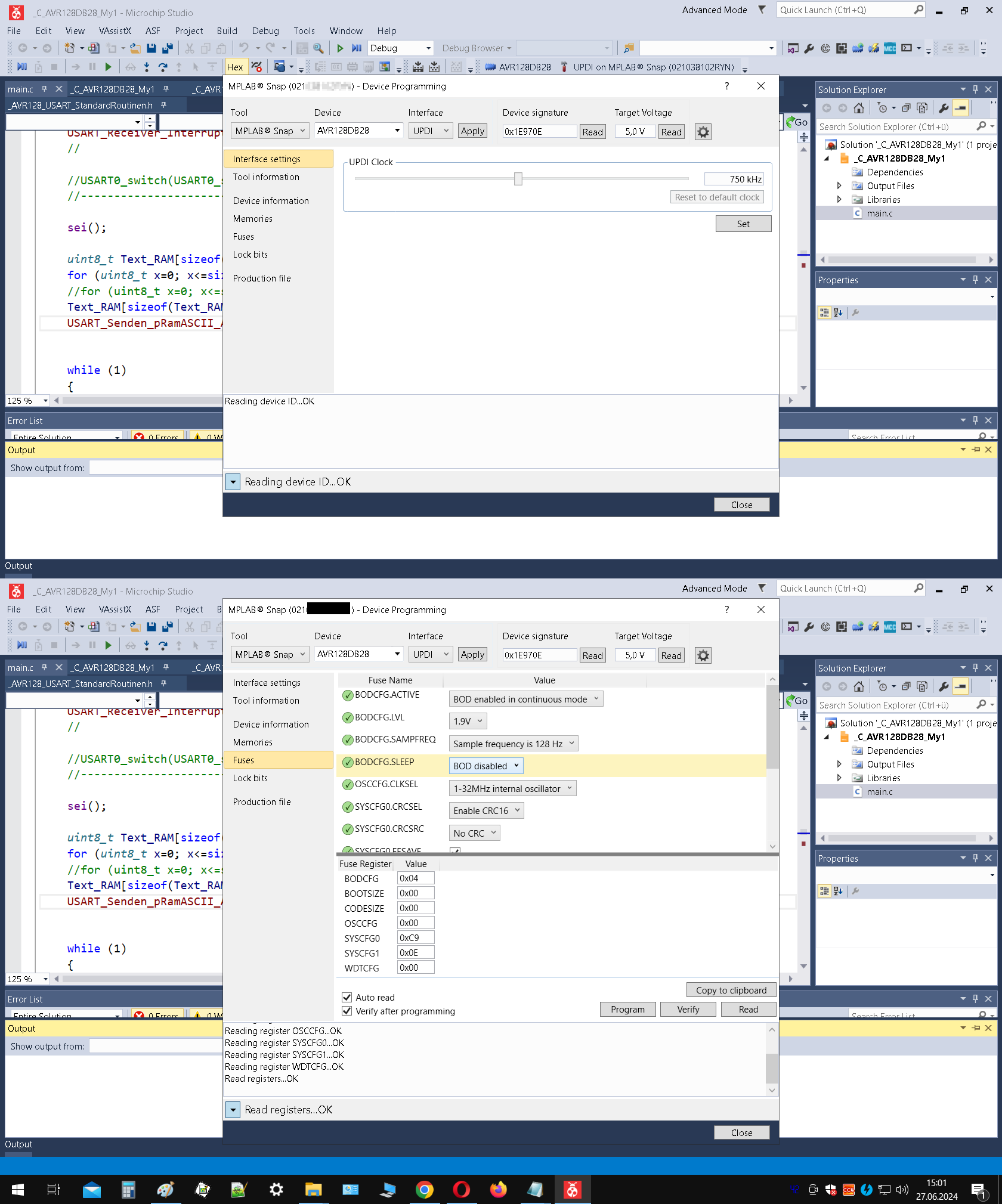
Screenshots der MPLAB Snap Software zur Programmierung
MPLAB Snap, AVR128DB28, Device Programming, Interface settings, Tool information, Fuse Name, Fuses, Device information, Memories, Production file, Lock bits, Target Voltage, Reading device ID... OK
in „MPLAP Snap halb im Nirvana“ · Mikrocontroller und Digitale Elektronik · · Screenshots
-
 Bild
Bild
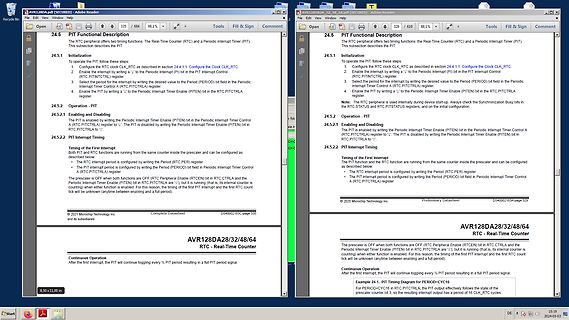
Ausschnitt eines Datenblatts für AVR128DA Mikrocontroller
AVR128DA28/32/48/64 RTC - Real-Time Counter 24.5 PIT Functional Description 24.5.1 Initialization 24.5.2 PIT Timing © 2021 Microchip Technology Inc.
in „AVR64EA28: PIT-Interrupt“ · Mikrocontroller und Digitale Elektronik · · Screenshots
-
PDF
ATMEGA8_DATENBLATT.pdf
AIO outputs shown in the port figure and the digital logic of the TWI module. 62 ATmega8(L) 2486X–AVR–06/10 ATmega8(L) Alternate Functions of The Port D pins with alternate functions are shown in Table 28. Port D Table 28. Port D Pins Alternate Functions Port Pin Alternate Function PD7 AIN1 (Analog
in „I2C/TWI TWBR > 10 warum?“ · Mikrocontroller und Digitale Elektronik ·
-
Datei
Cinni-Regler_V1-1.c
----------------------------- #include <stdio.h> #include <stdlib.h> #include <string.h> #include <avr/io.h> // Definitionen #include <avr/interrupt.h> #define F_CPU 8000000UL // CPU clock in Hertz #define USART_BAUDRATE 1200 #define BAUD_PRESCALE ((F_CPU / (USART_BAUDRATE * 16UL)) - 1) // ------ //
in „Vorstellung Drehzahlregler mit Triac in Steckergehäuse“ · Mikrocontroller und Digitale Elektronik ·
-
Datei
lcd.h
gmx.ch http://jump.to/fleury @see The chapter <a href="http://homepage.sunrise.ch/mysunrise/pfleury/avr-lcd44780.html" target="_blank">Interfacing a HD44780 Based LCD to an AVR</a> on my home page. */ /*@{*/ #if (__GNUC__ * 100 + __GNUC_MINOR__) < 303 #error "This library requires AVR-GCC 3.3 or later
in „LCD von Peter Fleury“ · Mikrocontroller und Digitale Elektronik ·
-
 Bild
Bild
MPLAB Snap Interface Einstellungen
MPLAB Snap, AVR128DB28, Interface settings, Tool information, Device, Interface, Device signature, Target Voltage, UPDI, Apply, 0x19E70E, Read, V, Fuse Name, Fuses, Memories, Production file, Lock bits, Reading device
in „neue AVR-µCs: Entwicklungsumgebung“ · Mikrocontroller und Digitale Elektronik · · Screenshots

-
Datei
lcd.h
ifndef LCD_H #define LCD_H #if (__GNUC__ * 100 + __GNUC_MINOR__) < 303 #error "This library requires AVR-GCC 3.3 or later, update to newer AVR-GCC compiler !" #endif #include <inttypes.h> #include <avr/pgmspace.h> /** * @name Definitions for MCU Clock Frequency * Adapt the MCU clock frequency in Hz to
in „Display geht immernoch nicht.“ · Mikrocontroller und Digitale Elektronik ·
-
Datei
wiring_analog.c
; } int analogRead(uint8_t pin) { uint8_t low, high; #if defined(analogPinToChannel) #if defined(__AVR_ATmega32U4__) if (pin >= 18) pin -= 18; // allow for channel or pin numbers #endif pin = analogPinToChannel(pin); #elif defined(__AVR_ATmega1280__) || defined(__AVR_ATmega2560__) if (pin >= 54) pin -= 54; // allow for channel or pin numbers #elif defined(__AVR_ATmega32U4__) if (pin >= 18) pin -= 18; // allow for channel or pin numbers #elif defined(__AVR_ATmega1284__) || defined(__AVR_ATmega1284P__) || defined(__AVR_ATmega644__) || defined(__AVR_ATmega644A
in „Arduino IDE mit Atmega32 - AD Wandler sind nicht benutzbar“ · Mikrocontroller und Digitale Elektronik ·
-
Datei
Firmware_v1.2.c
0) Temp = Temp + 32; if((PINB & (1<<5))==0) Temp = Temp + 64; if((PINB & (1<<4))==0) Temp = Temp + 128; if((PINB & (1<<3))==0) Temp = Temp + 256; //DIP-Switches einlesen *ENDE* if (Temp != 0) { DmxAddress= Temp; if (!(UCSRB &(1<<RXCIE))) //if receiver was disabled -> enable and wait for break { gDmxState
in „DMX steuerbaren RGB LED PAR oder Pinnspot selber bauen“ · Mikrocontroller und Digitale Elektronik ·
-
 Bild
Bild
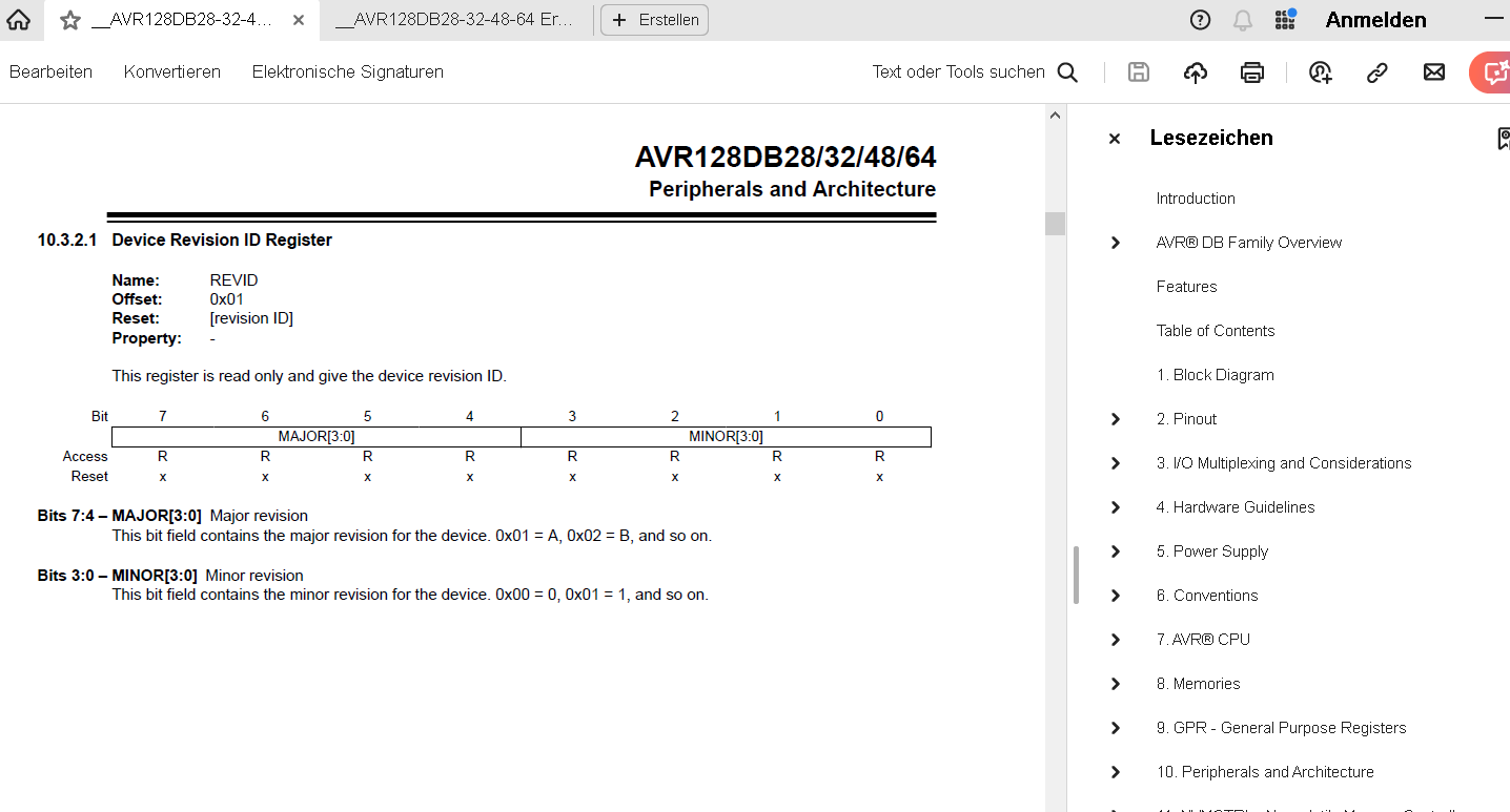
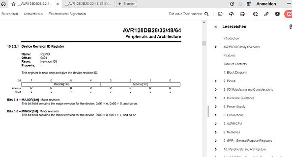
Datenblatt Ausschnitt AVR128DB Device Revision ID Register
AVR128DB28/32/48/64 Peripherals and Architecture 10.3.2.1 Device Revision ID Register Name: REVID Offset: 0x01 Reset: [revision ID] Property: This register is read only and give the device revision ID.
in „AVR128DA64 TCA1 funktioniert nicht mit alternativen Output?“ · Mikrocontroller und Digitale Elektronik · · Screenshots
-
Datei
app_bootloader.lst
1f 90 pop r1 3cda: 18 95 reti 00003cdc <send_msg.clone.1>: 3cdc: df 93 push r29 3cde: cf 93 push r28 3ce0: cd b7 in r28, 0x3d ; 61 3ce2: de b7 in r29, 0x3e ; 62 3ce4: 28 97 sbiw r28, 0x08 ; 8 3ce6: 0f b6 in r0, 0x3f ; 63 3ce8: f8 94 cli 3cea: de bf out 0x3e, r29 ; 62 3cec: 0f be out 0x3f, r0 ; 63 3cee
in „2 byte >> 1 word“ · Mikrocontroller und Digitale Elektronik ·