Unit VCC supply voltage -0.5 +7 V IK input clamping current VI< -0.5 V or I > VCC+ 0.5 V [1] - ±20 mA I output clamping current V < -0.5 V or V > V + 0.5 V [1] - ±20 mA OK O O CC O output current -0.5 V < O < VCC + 0.5 V; - ±25 mA except for pins nREXT/CEXT CC supply current - 50 mA GND ground current -50 - mA Tstg storage temperature -65 +150 °C P total power dissipation SO16 and DHVQFN16 packages [2] - 500 mW tot [1] The input and output voltage ratings may be exceeded if the input and output current ratings
Max Unit V CC supply voltage -0.5 +7 V IIK input clamping current V I -0.5 V or I > CC + 0.5 V - ±20 mA IOK output clamping current V O -0.5 V or VO> V CC+ 0.5 V - ±20 mA IO output current except for pins nREXT/CEXT; - ±25 mA V O -0.5 V to (CC + 0.5 V) ICC supply current - 50 mA IGND ground current -50 - mA T storage temperature -65 +150 °C stg P tot total power dissipation SO16 package [1] - 500 mW [1] For SOT109-1 (SO16) packagetoterates linearly with 12.4 mW/K above 110 °C. 8. Recommended operating
(später "FF") JSR SUB ; JumpToSubRoutine Zeitverzögerung DELAY. JMP M1 SUB: LDY #$01 ; SR Beginn SUBROUTINE M2: LDX #$DE ; mit ZP-ADRESSIERUNGSART sind durch IM ersetzt. M3: DEX BNE M3 DEY BNE M2
Reiner D. schrieb im Beitrag #7753924: > Stromerbrauch ? Irgendwas im zweistelligen mA-Bereich bei 5 V, oder ? Oder ESP32 nehmen im Mittel etwa 100mA auf, beim Senden 500mA. Und sie senden mehrmals pro Sekunde " ich bin noch da", weil WLAN das so will.
Apollo M. schrieb im Beitrag #7754846: > Meine ersten Programme waren C-Programme mit Python Syntax. Man sagt ja: Ein guter Programmierer kann ›C-Code‹ in jeder Programmiersprache schreiben! ;-)
...98....................................... ......................................................104....................................... P UAE......................................................115....................................... I Ultra S Deutsch HINWEIS: Technische Hinweise, die besonders
no sig_in_func99 1’d1 no C 100 sig_in_func_100 0 no sig_in_func100 1’d1 no 3 T 101 - - - - 1’d1 no M ( 102 - - - - 1’d1 no e 103 - - - - 1’d1 no G s B n 104 - - - - 1’d1 no a . 105 - - - - 1’d1 no k ) s 5 r Direct Direct I s Signal Input Signal Default Input via IO Output Signal Output enable signal
10 SRAM block 3.3-V or 5.0-V I/O on all devices (selectable in each LAB) Low power consumption (1 mA/MHz in standby mode; 1.5 to 2.5 mA/MHz in active mode) 84 to 208 pins available in plastic J-lead (PLCC) and plastic quad flat pack (PQFP) packages (see Table 1) Open-drain output option Joint Test
2SC3940A P — Ta I — V I — I C C CE C B 1.2 1.5 Ta=25˚C 1.2 ) VCE10V Ta=25˚C ( 1.0 1.25 1.0 C ) IB=10mA ) P A 9mA A ( 8mA ( o 0.8 IC 1.0 IC 0.8 a 7mA i n 6mA n s 0.6 r 0.75 r 0.6 d u 5mA u r r 4mA r w t t o 0.4 e 0.5 3mA e 0.4 r l l t C 2mA C e o 0.2 0.25 1mA 0.2 C 0 0 0 0 20 40 60 80 100 120 140 160
Lothar M. schrieb im Beitrag #7749856: > Was für welche? Hast du dir die Signale schon mal mit dem Oszi > angeschaut? Und auch die tatsächlichen Bitzeiten gemessen? Ich hatte von 0 Ohm über 100, 1k, 4,7k
Lothar M. schrieb im Beitrag #7749856: > Andreas B. schrieb: >> Die Abblock Cs sind sehr suboptimal angebunden. > Ich finde die gar nicht mal so schlecht für ein so ungünstig bepinntes > IC mit diametralen
equivalent to 10 ( ∗Meters) −1 ). For reference, copper at room temperature has a conductivityof 58 MS/m; a good silicon steel for motor laminations might have a conductivityof as low as 2 MS/m. Commodity-grade transformer laminations are more like 9 MS/m. You should note that conductivity generally has
Okay perfekt, danke dir. Auf dem Datenblatt steht jetzt noch peak current 1A und Continous current 65mA. Heißt ich kann da Problemlos mit 100mA arbeiten oder?
6 6 6 6 6 V33S 12 GND 0 0 3 6 2 1 0 0 + - + - + - + - + D C 0 + 1 + 2 + - + 3 + K C 5 A L I O I 1 M N ] ] M M M E E E E E E E E E E N C O O O O O O O O O O C N M S S P P P M U1 MAX:180mA P O [ [ P P P T X T X T X X X T X P P T X T X T X X X T X V / C I ] / ] WP 12HEADER 3 IN VO 4 O T N N O O O S /
processors-and-microcontrollers/arm-microcontrollers/i-mx-rt-crossover-mcus/i-mx-rt700-crossover-mcu-with-arm-cortex-m33-npu-dsp-and-gpu-cores:i.MX-RT700 ### SparkFun APA-104-1010 – 1x1mm kleine NeoPixel-LED Spätestens nach den Verfügbarkeitsproblemen mit LED-Treibern wie dem LED1202 ist klar, dass NeoPixel in
Edit: ich ziehe den Kommentar zurück. :-) ich dachte an APA102, APA104 sind wie WS2812.
erwartest Du für interne SATA-Stromversorgungsstecker? Die Pinbelegung steht im Handbuch auf S 104 (114 von 120). Die Zeichnung sieht aus wie SH (2mm) oder XH (2.54mm). Was ist daran jetzt so speziell? Notnagel: Nimm eine der USB-Stiftleisten. Da liegen 5V an.
zu bauen. Allerdings ist die Verlustleistung halt recht hoch. Die Intel 530 SSD nimmt allerdings 200mW. Bei 400 mW Last wären das also 1,2W Verlustleistung womit ich dann wieder einen Kühlkörper bräuchte. PS: Falsche Datei angehängt.
1 2 2 2 1 2 2 D 7 8 6 3 5 4 4 2 3 9 0 1 0 0 0 1 0 M R R 0 1 0 1 NQ 1 7 1 K 1 R 0 R 7 0 K 7 4 1 6 0 D C NQM 0 3 C C 5 4 2 2 L S1 7 4 1 M5 R104 8 D S 2 S 2 10R M 0 M 0 D n D n C 7 1 7 1 C C C 0 R 3 R 2 5 1 1 1 8 C 1 8 5 1 5 1 S 0 9 6 S1 3 6 1 6 1 M + M0
nicht ganz vollständig. 1. Es werden nur Silabs Chips unterstützt 2. Kein Debugger Support siehe AN104 Der erste Punkt ist einfach zu beheben, da man die Header Files der Eval Version verwenden kann. Nur das Anlegen eines Projekts ist etwas komplizierter. Der 2. Punkt ist kritischer da der TO ja
du ein 8051-Äquivalent dazu findest, nutze das, ansonsten wäre das ein guter Grund auf ARM Cortex-M zu wechseln.
- - 1 st Issue 1999. 8.30 LCY-99073A 17 Outline dimensions Changed 2000. 4.18 LCY-99073B 13 11-1 : M2.6 Tapping screw → M3 Tapping screw LCY-99073B-1 These specification sheets are the proprietary product of SHARP CORPORATION ("SHARP) and include materials protected under copyright of SHARP. Do not
min 9.8V DC On-state voltage, max 28.8V DC Off-state voltage, max 5V DC Off-state current, max 0.5 mA 1.5 mA On-state current, min 0.75 mA @ 10.8V DC 1.8 mA @ 10.8V DC 1.0 mA @ 15V DC 2.7 mA @ 15 V DC On-state current, nom 2.1 mA @ 24V DC 6 mA @ 24V DC On-state current, max 2.7 mA @ 28.8V DC 7.5 mA
13R102SBE 6 17R102UBE 10 10 Ω 1000 Ω 1000 e ( 105 e e e ( 105 e e l c l l l c l l d t s d d t s d 2 i 104 1 2 2 i 104 1 2 e e R 3 100 R 3 100 10 10 102 102 10 10 10 10 -50 0 50 100 150 200 -50 0 50 100 150 200 Temperature (°C) Temperature (°C) V max. DERATING VS. T amb Axis Title 120 10000 100 80 1000 n % e n l x 60 l l n m s n 2 V 1 2 40 100 Voltage duration ≤ 1000 h 20 Voltage duration ≤ 100 h Voltage duration ≤ 10 h 0 10 -50 -25 0 25 50 75 100 125 150 175 200 T (°C) amb Revision: 15-Dec-2023 4 Document Number: 29165
Baugruppen-Obersicht TNC355 neue Bardware-Ausführung (farblich gekennzeichnete Anschlußbuchsen) lw 355 m + s m 355 M + s LR355p/w M355C/G U355SN LE355at&~ IZ355svyR 254582 _. 254819.. 254Ba.. 249 516 .. 2m 517 .. 1 a49 652 .. x x x x x x 249663.. x x 249 8aß.. x x 249 823 .. x x BG. 23648407 x x x x x x
■ erv1ce CRT Data Display MODEL M-900 X X X Series Chassis No. YOSA Chassis Family No. 9Y08 MODEL M-1200 X X X Series Chassis No. YOS Chassis Family No. 12 YOS Model Model Model M-9004NA , M9009NA M-K12004NB, M-K12001NB M-12004NB M-9001NA, M-9009A Direct Drive Input Kit Type Direct Drive Input Direct Drive Input Model Model M-C12004N, M-C12001N M-C9004N, M-C9001N M-C12009N Compsite Video Input Compsite Video lnput Model M-12021PB, M-12021NB
Company value value Power input Input voltage range VIN IIN=40mA 0.9 1.5 V Input current range IIN VIN=1.2V, 3 40 mA L=10μH Off state current ISD VIN=1.2V, 22 μA VCE=0.4V power switch Switch on resistance RDS(ON) VIN=1.2V, 6 Ω IIN=40 mA L=10μ H Output leakage ILEAKAGE
Efficiency vs. Input Voltage at Various LED Cascaded Number Efficiency vs. input voltage @L=OUT384mA Efficiency vs. input voltage @L=OUT384mA Efficiency vs. input voltage @L=OUT769mA Page 8 of 27 SCT2932 1.5A LED Driver with Internal Switch Efficiency vs. input voltage @L=68uH, I =769mA OUT Efficiency
Thomas B. schrieb im Beitrag #7717994: > Der TBA810 ist besser der war im ITT Touring 104 drin und rauschte wie Hölle - im Touring 104A habe die dann mit einer zusätzlichen Transistorstufe das Rauschen reduziert
units of symbols in Maxwell’s equations Notation Quantity SI unit A H(r,t) magnetic field intensity m V E(r,t) electric field intensity m B(r,t) magnetic flux density T D(r,t) electric flux density C2 m J(r,t) electric current density A2 mC ρ(r,t) electric charge density m 3 A M(r,t) magnetization m V E
schreibst du aber nicht. Das ist korrekt. MIDI IN: Zwei mittels UART, sieben mittels SMs. Auf'm Kern0 MIDI OUT: Alle mittels der letzten verbliebenen SM über DMA. Auf'm Kern1
steuern. Norbert schrieb im Beitrag #7718397: > IDI IN: Zwei mittels UART, sieben mittels SMs. Auf'm Kern0 > MIDI OUT: Alle mittels der letzten verbliebenen SM über DMA. Auf'm Kern1 alles zu kompliziert. Ein kleiner ARM und es rennt! Wird ja in jedem MIDI-fähigen device so gemacht.

 Bild
 Bild
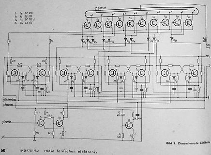
 Bild
 Bild
 Bild