-
Datei
main.c
Date: $ ID: $Id: $ **********************************************************************/ #include "stm32f4xx_conf.h" #include "stm32f4xx.h" #include "stm32f4xx_spi.h" int main(void) { init_SPI1(); while(1) { } } void init_SPI1(void) { GPIO_InitTypeDef GPIO_InitStruct; SPI_InitTypeDef SPI_InitStruct;
in „STM32F4 SPI1 Slave“ · Mikrocontroller und Digitale Elektronik ·
-
Datei
adc_test.c
/* ------------------------------------------------------- adc_test.c MCU : STM8S103F3 Takt : interner Takt 16 MHz 19.05.2016 R. Seelig ------------------------------------------------------ */ #include "stm8s.h" #define u_ref 331ul // gemessene Betriebsspg.: 3.31 V ( * 100 ) #
in „STM8 und ADC“ · Mikrocontroller und Digitale Elektronik ·
-
Datei
main.c
#include "stm32f10x_lib.h" #include "stm32f10x_map.h" #include "stm32f10x_rcc.h" #include "stm32f10x_gpio.h" #include "bits.h" #define STACK_TOP 0x20000800 #define NVIC_CCR ((volatile unsigned long *)(0xE000ED14)
in „Problem mit STM32-H103+Eclipse+OpenOCD“ · Mikrocontroller und Digitale Elektronik ·
-
Datei
stm32f4xx_rng.c
**** */ /* Includes ------------------------------------------------------------------*/ #include "stm32f4xx_rng.h" #include "stm32f4xx_rcc.h" /** @addtogroup STM32F4xx_StdPeriph_Driver * @{ */ /** @defgroup RNG * @brief RNG driver modules * @{ */ /* Private typedef ----------------------------------
in „Random Number Generator läuft nicht richtig,stm32f429“ · Mikrocontroller und Digitale Elektronik ·
-
Datei
main.c
------------------------------------------------ // SPI support functions // SPI transfer Byte uint8_t spi1_tx(uint8_t tx) { while ((SPI1->SR & SPI_I2S_FLAG_BSY)) { // Nothing } // write data to be transmitted to the SPI data register SPI1->DR = tx; // when receive buffer is empty ... or rxne, txe, !bsy? while (!(SPI1->SR & SPI_I2S_FLAG_RXNE)) { // Nothing } return ((uint8_t)(SPI1->DR)); // return received data from SPI data register } // other support functions (delay, uart, ...) void SysTick_Handler(void) // IRQ! { SysTickCnt
in „SPI-RAM-Bank an STM32F0-Discovery - write, kein read“ · Mikrocontroller und Digitale Elektronik ·
-
Datei
eeprom.c
I2C_EVENT_MASTER_RECEIVER_MODE_SELECTED) != SUCCESS) return 0xff; /* Wichtiger Hinweis, bzgl der Reihenfolge des Bit Setzens, Manual. STM32F407, S834 Die Konfiguration muss VOR dem Buszugriff erfolgen, d.h. das Datenbyte wird erst ganz zum Schluss ausgelesen */ // NACK einstellen E2PROM anzuzeigen, dass keine weiteren Daten angefordert
in „STM32F4xx: 24LC512 EEPROM Zugriffsroutinen“ · Projekte & Code ·
-
Datei
NF-Generator-407.c
/* STM32F407 www.mino-elektronik.de 2016-11-08 */ #include <stdio.h> #include <stdint.h> #include <stdlib.h> #include <stm32f4xx.h> #include <stm32f4xx_gpio.h> #include <stm32f4xx_rcc.h> // LCD-Routinen in anderem Programmteil extern void lcd_zeile1(char *s); extern void lcd_zeile2(char *s); extern void lcd_zeile3(char *s); extern void lcd_zeile4(char *s); void lcd_init(void); #define F_CLOCK 168e6 // zum genauen Abgleich bitte anpassen! #define F_START
in „Frequenz Erzeugung mit avr“ · Mikrocontroller und Digitale Elektronik ·
-
PDF
STM32_Ethernet_Start_Point_20180307.pdf
GettingStartedwithEthernetontheSTM32Nucleo Using STM32CubeMX with Light-Weight IP (LwIP) and System Workbench for STM32 (Eclipse) Daniel W Rickey CancerCare Manitoba drickey@cancercare.mb.ca 2018-03-07 Introduction TheNucleoboardsproducedbySTMicroelectronicsarewonderfullypowerfulandcheap
in „STM32 LwIP + HTTPD“ · Mikrocontroller und Digitale Elektronik ·
-
Datei
kk_bb.c
wait _delay_ms(1000) #define wait10 do{_delay_ms(3333);_delay_ms(3333);_delay_ms(3333);}while(0) //2^8 = 256 //2^16 = 65.536 //2^32 = 4.294.967.296 //2^64 = 18.446.744.073.709.551.616 #define u8 uint8_t //255 #define u16 uint16_t//65.535 #define u32 uint32_t// 4.294.967.295 #define i8 int8_t //+-127 #
in „Problem FatFS + SPI“ · Mikrocontroller und Digitale Elektronik ·
-
Datei
build.xml
<?xml version="1.0" encoding="UTF-8" standalone="no"?> <project default="postbuild" name="test"> <property name="project.name" value="STM32F4_Discovery_CoOS"/> <property name="project.debug" value="Debug"/> <property name="project.obj"
in „STM32F4 CoOS“ · Mikrocontroller und Digitale Elektronik ·
-
Datei
eeprom.c
I2C_EVENT_MASTER_RECEIVER_MODE_SELECTED) != SUCCESS) return 0xff; /* Wichtiger Hinweis, bzgl der Reihenfolge des Bit Setzens, Manual. STM32F407, S834 Die Konfiguration muss VOR dem Buszugriff erfolgen, d.h. das Datenbyte wird erst ganz zum Schluss ausgelesen */ // NACK einstellen E2PROM anzuzeigen, dass keine weiteren Daten angefordert
in „Organisation der Header und Includes“ · Mikrocontroller und Digitale Elektronik ·
-
PDF
OLIMEX-stm32-p107-schematic.pdf
R4 C12 B0_0/B0_1 12 PC5/ADC12_IN15/ETH_MII_RXD1/ETH_RMII_RX63 STAT1 TRST 3 4 CMD/DI 6 OSC_IN PC6/I2S2_MCK/TIM3_CH164 STAT2 PC6 TDI 5 6 VSS 4 27pF PC7/I2S3_MCK/TIM3_CH2 PC7 TMS VDD SPI1_SCK Q1 R14 PC8/TIM3_CH3 65 PC8 7 8 CLK/SCLK 5 Q25.000MHz/HC-49SM(SMD)/20pF NA PC9/TIM3_CH4 66 PC9 TCK 9 10 DAT0/DO
in „Streuung der ADC-Werte beim STM32“ · Mikrocontroller und Digitale Elektronik ·
-
Datei
eventctrl_uc.ino
---------------------- Objektinstanz von shiftreg595 erstellen Usage: shiftreg595::shiftreg595(uint8_t clk, uint8_t dat, uint8_t stb) ---------------------------------------------------------------------- */ // shiftreg595 sr(2, 3, 15); // stm32 r3-Board (PB7, PB6, PB13) // shiftreg595 sr(5, 3, A2);
in „Schulnotenbewertung eines Arduino-Programms“ · Mikrocontroller und Digitale Elektronik ·
-
 Bild
Bild
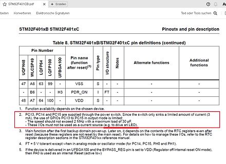
Ausschnitt einer Pin-Definitionstabelle aus einem Datenblatt
STM32F401xB STM32F401xC Pinouts and pin description Table 8. STM32F401xB/STM32F401xC pin definitions (continued) Pin Number UQFN48 WLCSP40 LQFP64 LQFP100 UFBGA100 Pin name (function after reset)(1) Pin
in „STM32 Timer2 Interrupt“ · Mikrocontroller und Digitale Elektronik · · Screenshots
-
 Bild
Bild
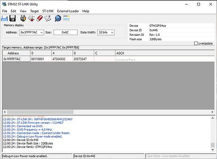
STM32 ST-LINK Utility Memory Display
STM32 ST-LINK Utility Device STM32F04xx Address: 0x1FFFF7AC Size: 0x0C Data Width: 32 bits Device ID 0x445 Revision ID Rev 1.0 Flash size 32KBytes Target memory, Address range: [0x1FFFF7AC 0x1FFFF7B8] Address 0 4 8 C ASCII 0x1FFFF7AC 00110001 47304302 2037247 12:00:24 : ST-LINK SN: 56FF6F064850664941252467 12:00:24 : ST-LINK Firmware version : V2J44S7 12:00:24 : Connected via SWD. 12:00:24 : SWD Frequency = 4,0
in „STM32F042 gecloned aber verhält sich seltsam“ · Mikrocontroller und Digitale Elektronik · · Screenshots
-
Datei
MyFunctions.c
Geraet: ******************************************************************************/ #include <stm32f10x_conf.h> #include "MyFunctions.h" #include "EXTI_HW_Init.h" #include <stm32f10x_spi.h> #include <stdio.h> #include "stm32f10x_usart.h" // globale Variablen // statische Variablen uint8_t s_Rx =0,s_Tx =0; uint8_t s_Rx_control =2,s_Tx_control =2,s_Tx_check =0,s_Rx_check =0; uint8_t s_stop =0; uint8_t s_count =0; char s_RT; char s_C8; // Macros /***************************************************
in „UART Problem beim senden“ · Mikrocontroller und Digitale Elektronik ·
-
Datei
irsnd.c
---------------- */ void irsnd_init (void) { #ifndef ANALYZE # if defined(PIC_C18) // PIC C18 or XC8 compiler # if ! defined(__12F1840) // only C18: OpenTimer; # endif irsnd_set_freq (IRSND_FREQ_36_KHZ); // default frequency IRSND_PIN = 0; // set IO to outout PWMoff(); # elif defined (ARM_STM32) //
in „IRMP - Infrared Multi Protocol Decoder“ · Projekte & Code ·
-
Datei
irsnd.c
---------------- */ void irsnd_init (void) { #ifndef ANALYZE # if defined(PIC_C18) // PIC C18 or XC8 compiler # if ! defined(__12F1840) // only C18: OpenTimer; # endif irsnd_set_freq (IRSND_FREQ_36_KHZ); // default frequency IRSND_PIN = 0; // set IO to outout PWMoff(); # elif defined (ARM_STM32) //
in „IRMP - Infrared Multi Protocol Decoder“ · Projekte & Code ·
-
Datei
main.c
-----------------------------------------------*/ #include <stdlib.h> #include <stdio.h> #include "stm32f1xx_hal.h" #include "bme280.h" #include "u8g.h" #include "u8g_com_arm_stm32.h" /* USER CODE BEGIN Includes */ /* USER CODE END Includes */ /* Private variables ------------------------------------
in „STM32 F103 - I2C Probleme“ · Mikrocontroller und Digitale Elektronik ·
-
Datei
rs485.c
#include "stm32f10x.h" #include <stm32f10x_gpio.h> #include <stm32f10x_rcc.h> #include <typedef.h> #include <init.h> #include "stm32f10x_adc.h" #include "stm32f10x_dac.h" #include "stm32f10x_usart.h" #include "stm32f10x_dma.h" #include "misc.h" extern sRS485Data RS485_Data; void InitHardware() { GPIO_InitTypeDef GPIO_InitStructure; ADC_InitTypeDef ADC_InitStructure; DAC_InitTypeDef DAC_InitStructure; NVIC_InitTypeDef NVIC_InitStructure; DMA_InitTypeDef
in „STM32 Tutorial“ · Mikrocontroller und Digitale Elektronik ·
-
PDF
Bulb_Ohm.pdf
monolithic integrated circuit. At ±14V or 28V, the guaranteed output power is 12W on a 4Ω load and 8W on an 8Ω.” 1. Problem: How can we drive a TDA2030 with a U = 3,3V Black Pill? In a first step we need a little bit higher currents to demonstrate the variable resistance of a bulb’s coiled filament
in „I2C STM32F103“ · Mikrocontroller und Digitale Elektronik ·
-
Datei
mmc_stm32f1.c
cleared */ while (SPI_I2S_GetFlagStatus(SPI1, SPI_I2S_FLAG_BSY) == SET); d = SPI_I2S_ReceiveData(SPI1); buff[1] = d; buff[0] = d >> 8; SPI_8Bit(); } #if _USE_WRITE /* Send multiple byte */ static void xmit_spi_multi ( const uint8
in „STM32Fxxx: Frage zur Initialisierung mit der StdPeriphLib“ · Mikrocontroller und Digitale Elektronik ·
-
Datei
mmc_stm32f1.c
cleared */ while (SPI_I2S_GetFlagStatus(SPI1, SPI_I2S_FLAG_BSY) == SET); d = SPI_I2S_ReceiveData(SPI1); buff[1] = d; buff[0] = d >> 8; SPI_8Bit(); } #if _USE_WRITE /* Send multiple byte */ static void xmit_spi_multi ( const uint8
in „STM32F103: Problem mit ChanFat und SD karte“ · Mikrocontroller und Digitale Elektronik ·
-
PDF
STLinkMini.pdf
R6 10k BOOT1 20 39 PB2 PB3 1 2 3 4 40 PB4 C C C C 41 PB5 I2C1_SCL 42 I2C1_SDA 43 PB6 PB7 TP2 45 PB8 TP3 46 PB9 +3,3V TP4 21 PB10 X2 22 R9 100 TP5 25 PB11 PB12 26 PB13 1 RST R11 22 T_NRST T_JTMS 27 PB14 2 28 3 SWCLK R10 22 T_JTCK PB15 4 STM32F103C8T6 5 RX R14 22 STLINK_RX 6 7 TX R13 22 STLINK_TX 8 T_JTMS
in „STM32F103C8T6.“ · Mikrocontroller und Digitale Elektronik ·
-
PDF
STLinkMini.pdf
R6 10k BOOT1 20 39 PB2 PB3 1 2 3 4 40 PB4 C C C C 41 PB5 I2C1_SCL 42 I2C1_SDA 43 PB6 PB7 TP2 45 PB8 TP3 46 PB9 +3,3V TP4 21 PB10 X2 22 R9 100 TP5 25 PB11 PB12 26 PB13 1 RST R11 22 T_NRST T_JTMS 27 PB14 2 28 3 SWCLK R10 22 T_JTCK PB15 4 STM32F103C8T6 5 RX R14 22 STLINK_RX 6 7 TX R13 22 STLINK_TX 8 T_JTMS
in „Erstes PCB mit Eagle: STM32 Breakout Board“ · Platinen ·
-
Datei
startup_stm32f10x_hd.c
IRQHandler(void); void WEAK RTCAlarm_IRQHandler(void); void WEAK USBWakeUp_IRQHandler(void); void WEAK TIM8_BRK_IRQHandler(void); void WEAK TIM8_UP_IRQHandler(void); void WEAK TIM8_TRG_COM_IRQHandler(void); void WEAK TIM8_CC_IRQHandler(void); void WEAK ADC3_IRQHandler(void); void WEAK FSMC_IRQHandler(void)
in „STM32F10x mit Eclipse, yagarto (GCC) und J-Link (GDB)“ · Mikrocontroller und Digitale Elektronik ·
-
PDF
kicad_vergleich_v_03.pdf
MCU_Microchip_PIC32.dcm 13 30-10-2017 MCU_NXP_Kinetis.dcm 146 30-10-2017 MCU_NXP_LPC.dcm 93 30-10-2017 MCU_NXP_S08.dcm 189 30-10-2017 MCU_Parallax.dcm 3 30-10-2017 MCU_ST_STM32.dcm 799 30-10-2017 MCU_ST_STM8.dcm 7 30-10-2017 MCU_Texas_MSP430.dcm 357 30-10-2017 mechanical.dcm 6 24-08-2017 Mechanical.dcm 6 30-10-
in „Neues bei KiCAD Nightly-Builds ab 2017 Okt.“ · Platinen ·
-
Datei
mmc_stm32f1.c
); /* SPI für LCD ILI9341 einschalten */ SPI_Cmd(SPI1, ENABLE); } /* Exchange a byte */ static uint8_t xchg_spi (uint8_t dat) /* Data to send */ { while (SPI_I2S_GetFlagStatus(SPI1, SPI_I2S_FLAG_TXE) == RESET); /* Wait for SPIz Tx buffer empty */ SPI_I2S_SendData(SPI1,dat); /* Send SPI1 data */ while
in „STM32Fxxx: Frage zur Initialisierung mit der StdPeriphLib“ · Mikrocontroller und Digitale Elektronik ·
-
Datei
Stm32F030_uart.cpp
#include <stdint.h> #include "Pipe.h" #include "stm32f030x6.h" #include "stm32f0xx_hal.h" Pipe<32, uint8_t> ReceiverQueue; Pipe<32, uint8_t> SendQueue; extern UART_HandleTypeDef huart1; bool s_IsSending_bt = false; uint8_t s_EchoCnt_u8 = 0U; const uint32
in „STM32F030 ParityError nur bei aktiviertem RXNEIE?“ · Mikrocontroller und Digitale Elektronik ·
-
Datei
main.c
main.c ** ** Abstract : main function. ** ** Functions : main ** ** Environment : Atollic TrueSTUDIO/STM32 ** STMicroelectronics STM32F10x Standard Peripherals Library ** ** Distribution: The file is distributed as is, without any warranty ** of any kind. ** ** (c)Copyright Atollic AB. ** You may use this
in „helix MP3 Decoder, gibt keinen error aber auch keine Daten“ · Mikrocontroller und Digitale Elektronik ·
-
Datei
main.c
***********************************************************************/ // Header Files #include <stm32f10x_gpio.h> #include "GPIO_HW_Init.h" #include "MyFunctions.h" #include "USART_HW_Init.h" #include "SPI_HW_Init.h" #include "EXTI_HW_Init.h" #include "NVIC_HW_Init.h" #include <stm32f10x_conf.h> #include <stm32f10x_spi.h> #include <stm32f10x_exti.h> // #defines // globale Variablen // void EXTI_Line_SyncDis( FunctionalState STATE ); int main () { /******************* Hardware Initialisation *************
in „UART Problem beim senden“ · Mikrocontroller und Digitale Elektronik ·
-
Datei
eeprom.c
I2C_EVENT_MASTER_RECEIVER_MODE_SELECTED) != SUCCESS) return 0xff; /* Wichtiger Hinweis, bzgl der Reihenfolge des Bit Setzens, Manual. STM32F407, S834 Die Konfiguration muss VOR dem Buszugriff erfolgen, d.h. das Datenbyte wird erst ganz zum Schluss ausgelesen */ // NACK einstellen E2PROM anzuzeigen, dass keine weiteren Daten angefordert
in „GCC Optimierung killt Funktion“ · Mikrocontroller und Digitale Elektronik ·
-
PDF
Schematic_ED2109-015-A.pdf
VUSB D5 +5V 10 1 2 1k R9 T1 RX2 BC857C 1 2 Vishay SL22-E3/52T 1k T5 D1 BC847C GND TX2 R1 T6 R11 R5 R8 +VBAT GND 1.5..4.5V -> 5V D3 NichiconUWT1V221MNL1GS D7 1k BC847C 22k 3.3k 82 L1 1 2 1 2 +5V U1 +3.3V LL4148 1 5 S R12 6.8uH C7 C6 Vishay SL22-E3/52T IN OUT G 150k Vishay SL22-E3/52T 1uF L C3 220 µF 3
-
Datei
pinouts.txt
################################################################## STM8S103F3P6 Pinout ################################################################## ------------ UART1_CK / TIM2_CH1 / PD4 | 1 20 | PD3 / AIN4 / TIM2_CH2 / ADC_ETR UART1_TX / AIN5 / PD5 | 2 19 | PD2
in „STM8S Minimumboard + SSD1306 OLED Display“ · Projekte & Code ·
-
PDF
bom-v1-0.pdf
REF 3020 AIDBZT 1,35 € 1,35 € U22 1MCP6542, 2x comparator MCP 6542-I/SN 0,55 € 0,55 € U50 1AT45DB641-S, 64MBit SPI flash AT45DB641E-SHN 3,58 € 3,58 € U60 1STM32L452RET, 80MHz, 160KiB RAM 189-4029 8,22 € 8,22 €min order 2 U61 1Low power comparator, 1x MCP 65R41T-2402E 0,43 € 0,43 € U100, U101 2BD6221F-E2
in „Universalplatine für STM32, grobe Fehler vor der Herstellung?“ · Mikrocontroller und Digitale Elektronik ·
-
Datei
controller.c
, 0x1E, 0x1F, 0x20}; u8 SPI1_Buffer_Rx[BufferSize]; //for read actions u8 TxIdx = 0, RxIdx = 0, k = 0; //setting SPI's control variables and counter k int main(void) { RCC_APB2PeriphClockCmd(RCC_APB2Periph_GPIOA | RCC_APB2Periph_GPIOB
in „STMF32, SPI, Master, Vollduplex“ · Mikrocontroller und Digitale Elektronik ·
-
Datei
main.c
/* Includes ------------------------------------------------------------------*/ #include "stm32f0xx.h" #include "stm32f0xx_rcc.h" #include "stm32f0xx_gpio.h" GPIO_InitTypeDef GPIO_InitStructure; volatile uint32_t Milliseconds = 0, Seconds = 0; void SysTick_Handler(void){ Milliseconds++; //Increment
in „STM32F0: Systick will nicht wenn mit gcc unter linux compiliert“ · Mikrocontroller und Digitale Elektronik ·
-
PDF
Minimalbeschaltung_MCU.pdf
U2A PA0 STM32F4X5RG U2B STM32F4X5RG 14 PA0/WKUP PC0 8 15 9 18 19 PA1 16 PA1 PC1 10 63 VSS_2 VDD_2 32 V33 U_TX 17 PA2 PC2 11 PC2 VSS VDD_3 48 U_RX PA3 PC3 T_1 VDD_4 20 PA4 PC4 24 INH_M 12 VSSA VDD 64 21 PA5 PC5
in „Kontrollblick Minimalbeschaltung STM32F405RGT7“ · Mikrocontroller und Digitale Elektronik ·
-
Datei
mmc_stm32f1.c
auf den 8 Bit Mode ---------- */ void SPI_8Bit() { /* SPI abschalten */ while (SPI_I2S_GetFlagStatus(SPI1, SPI_I2S_FLAG_BSY) == SET); SPI_Cmd(SPI1, DISABLE); /* 16 Bit auf 8 Bit setzen */ SPI1->CR1 &= ~SPI_CR1_DFF; /* SPI wieder einschalten */ SPI_Cmd(SPI1, ENABLE); } /* Exchange a byte */ static uint8_t xchg_spi (uint8_t dat) /* Data to send */ { while (SPI_I2S_GetFlagStatus(SPI1, SPI_I2S_FLAG_TXE) == RESET); /* Wait for SPIz Tx buffer empty */ SPI_I2S_SendData(SPI1,dat); /* Send SPI1 data */ while
in „STM32F103: Problem mit ChanFat und SD karte“ · Mikrocontroller und Digitale Elektronik ·
-
Datei
mmc_stm32f1.c
auf den 8 Bit Mode ---------- */ void SPI_8Bit() { /* SPI abschalten */ while (SPI_I2S_GetFlagStatus(SPI1, SPI_I2S_FLAG_BSY) == SET); SPI_Cmd(SPI1, DISABLE); /* 16 Bit auf 8 Bit setzen */ SPI1->CR1 &= ~SPI_CR1_DFF; /* SPI wieder einschalten */ SPI_Cmd(SPI1, ENABLE); } /* Exchange a byte */ static uint8_t xchg_spi (uint8_t dat) /* Data to send */ { while (SPI_I2S_GetFlagStatus(SPI1, SPI_I2S_FLAG_TXE) == RESET); /* Wait for SPIz Tx buffer empty */ SPI_I2S_SendData(SPI1,dat); /* Send SPI1 data */ while
in „STM32F103 diskio.c für Chan FatFs SD Karten Treiber“ · Projekte & Code ·
-
PDF
navico_3g.pdf
485 Designator Package Pins Marking Manufacturer MPN Description Q27 P506TVC50 F7240 IR Q5 PSMND70 Q8 FDS6912A on semi Dual n-ch mosfets, 30V, 6A Q9 FDS6912A on semi Dual n-ch mosfets, 30V, 6A U1 TI5420 TPS54240 2.5A Buck U10 QFN Mega48V Atmel Microcontroller U11 TI5420 TPS54240 2.5A Buck U13 Mcimx6s5dvm10ab
in „Reparaturbericht: i.MX6 Resetschaltung in Navico Schiffsradar“ · Mikrocontroller und Digitale Elektronik ·
-
Datei
mmc_stm32f1.c
Exchange a byte */ static uint8_t xchg_spi (uint8_t dat) /* Data to send */ { while (SPI_I2S_GetFlagStatus(SPI1, SPI_I2S_FLAG_TXE) == RESET); /* Wait for SPIz Tx buffer empty */ SPI_I2S_SendData(SPI1,dat); /* Send SPI1 data */ while
in „STM32F103 diskio.c für Chan FatFs SD Karten Treiber“ · Projekte & Code ·
-
Datei
SHT11.asm
;---------------------------------------------------------------------------------------- ; CRC x^8+x^5+x^4+1 ; 21 Word/131 Cycles (32µs @ 4MHz) ; ; in : r16 Byte ; r17 CRC alt ; out : r17 CRC neu sht11_crc: push r16 push r18 push r19 ldi r19,8 ; 8 Bits sht11_crc10: clr r18 lsl r16 ror r18 ; Bit7 nach
in „SHT71 Assembler Code für Atmega8“ · Mikrocontroller und Digitale Elektronik ·
-
Datei
stm32-timer.h
_1 ) #define TIM_CCMR1_IC2PSC_by8 (TIM_CCMR1_IC2PSC_1|TIM_CCMR2_IC2PSC_0) #define TIM_CCMR1_CC2S_output 0 #define TIM_CCMR1_CC2S_inTI2 ( |TIM_CCMR1_CC2S_0) #define TIM_CCMR1_CC2S_inTI1 (TIM_CCMR1_CC2S_1 ) #define TIM_CCMR1_CC2S_inTRC
in „CMSIS und GNU Support“ · Mikrocontroller und Digitale Elektronik ·
-
Datei
main.c
configured, this is done through SystemInit() function which is called from startup file (startup_stm32f10x_xx.s) before to branch to application main. To reconfigure the default setting of SystemInit() function, refer to system_stm32f10x.c file */ /* System Clocks Configuration */ RCC_Configuration
in „Timer/Counter STM32“ · Mikrocontroller und Digitale Elektronik ·
-
Datei
simple_server.c
ADUC7026 **********************************************/ #include "..\main\include.h" #define PSTR(s) s //extern void delay_ms(u8 ms); // please modify the following two lines. mac and ip have to be unique // in your local area network. You can not have the same numbers in // two devices: static u8
in „Webpage Webserver“ · Mikrocontroller und Digitale Elektronik ·
-
Datei
WS2812Ctrl.h
04.05.2015 $ ID: $Id: WS2812Ctrl $ */ #ifndef WS2812CTRL_H_INCLUDED #define WS2812CTRL_H_INCLUDED #include "stm32f10x.h" #include "stm32f10x_ts.h" #define COLOR_CODING_RGB_DIRECT 0 #define COLOR_CODING_RGB 1 #define COLOR_CODING_HSV 3 typedef struct { uint8_t Coding; // Color Coding union { uint8_t h; uint8_t r; }; union { uint8_t s; uint8_t g; }; union { uint8_t v; uint8_t b; }; } COLOR; void initWS2812(void); uint8_t doTransferWS2812(COLOR *_pLEDData, uint16_t _nLED); #endif /* WS2812CTRL_H_INCLUDED */
-
Datei
stm32f4x7_eth_bsp.c
/** ****************************************************************************** * @file stm32f4x7_eth_bsp.c * @author MCD Application Team * @version V1.1.0 * @date 31-July-2013 * @brief STM32F4x7 Ethernet hardware configuration. ************************************************************
in „Olimex STM32E407, FreeRTOS und lwip“ · Mikrocontroller und Digitale Elektronik ·
-
PDF
project.pdf
PB13 M1INB X X X Motor Drivers N 25 PA2 0 1 2 3 4 5 0 1 P PB12 51 M1INA T T T C36 G A S D A A A A C C B B B E E E E E E E E E B B C D A D 1uF P V V P P P P P P P P P P P P P P P P P P P P V V C33 100nF 6 7 8 9 0 1 2 3 4 5 6 7 8 9 0 1 2 3 4 5 6 7 8 9 0 STM32F407VGT6 +5V +5V P2 +5V P3 2 2
in „Schaltplan so richtig? STM32F407VG“ · Mikrocontroller und Digitale Elektronik ·
-
Datei
main.c
************************************************** */ /* Includes */ #include <stddef.h> #include "stm32f10x.h" #include "stm32f10x_gpio.h" #include "stm32f10x_tim.h" #include "main.h" #include "SysTickHandler.h" #include "abstraction.h" #include <math.h> #include "IRQ_Handler.h" //#include "STM32vldiscovery.h
in „Konfiguration eines Timers auf dem STM32F100RB6“ · Mikrocontroller und Digitale Elektronik ·