-
 Bild
Bild
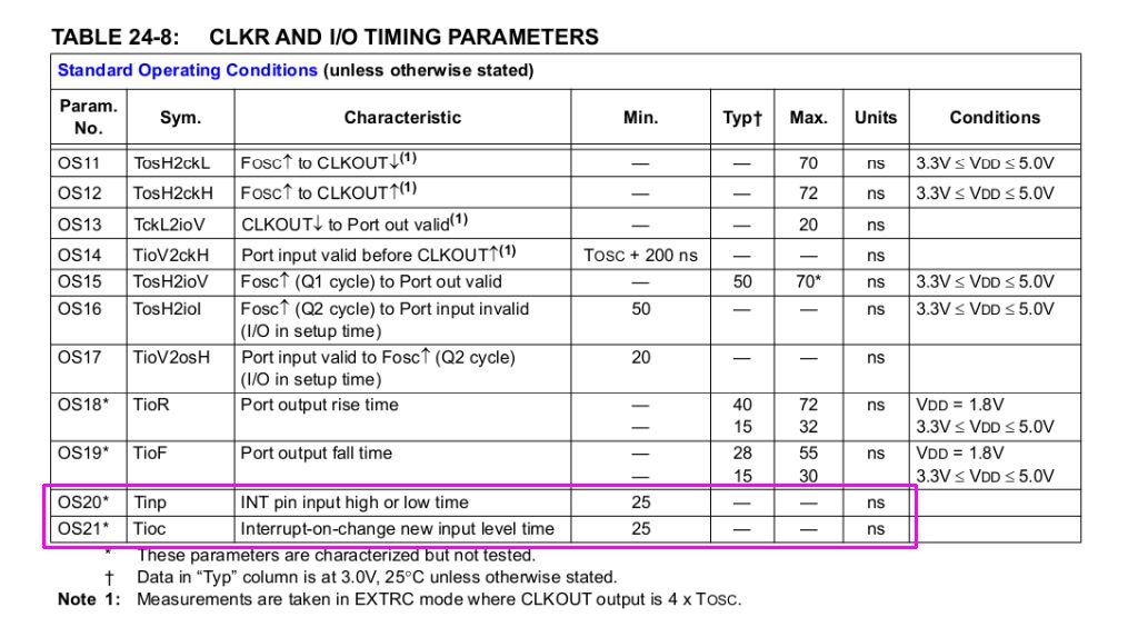
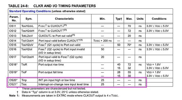
Tabelle mit CLKR und I/O Timing Parametern
TioF Port output fall time 28 55 ns VDD = 1.8V 15 30 ns 3.3V ≤ VDD ≤ 5.0V OS20* Tinp INT pin input high or low time 25 ns OS21* Tioc Interrupt-on-change new input level time 25 ns
-
Thread
EmbeddedWorld 2026, Catch-All – Bauteile, Stromversorgungen, Meshnetze uvam
zwei neue Controller nach folgendem Schema: [c] · Our New 32-bit MCU Lineup: Featuring the high-performance A34G34A (Cortex-M4F, 200MHz, 2MB Dual Bank) and the A31C144 entry-level series. The G43A demo showcases high-quality graphic LCDs powered by the LVGL library for modern appliance UIs. [
ins Rennen: [c] With the Proteus-IV and Ophelia-IV components, Würth Elektronik presents two new high-performance RF modules based on the latest Nordic nRF54L15-SoC semiconductor. The two modules differ only in terms of their firmware: Proteus-IV is a ready-to-use Bluetooth low-energy 6.0 module with
-
 Bild
Bild
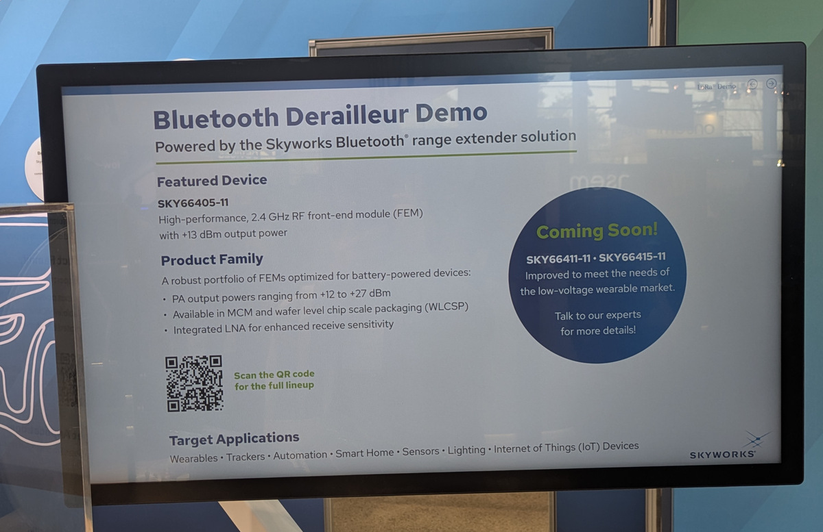
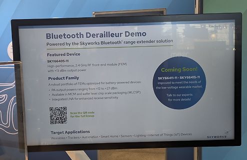
Präsentation von Skyworks Bluetooth-Lösungen auf einem Monitor
Derailleur Demo Powered by the Skyworks Bluetooth® range extender solution Featured Device SKY66405-11 High-performance, 2.4 GHz RF front-end module (FEM) with +13 dBm output power Product Family A robust portfolio of FEMs optimized for battery-powered devices: • PA output powers ranging from +12 to +27 dBm
-
 Bild
Bild
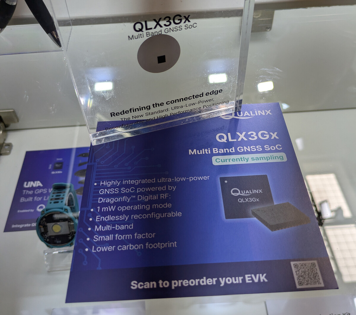
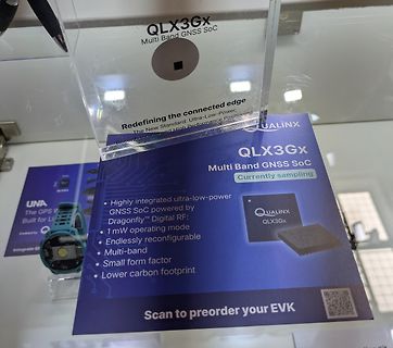
Werbeaufsteller für QLX3Gx GNSS SoC
QLX3Gx Multi Band GNSS SoC Redefining the connected edge The New Standard: Ultra-Low-Power, Reconfigurable and High Performance Positioning QUALINX QLX3Gx Multi Band GNSS SoC Currently sampling • Highly integrated ultra-low-power GNSS SoC powered by Dragonfly™ Digital RF; • 1 mW operating mode • Endlessly reconfigurable • Multi-band • Small form factor • Lower carbon footprint Scan to preorder your EVK
-
 Bild
Bild
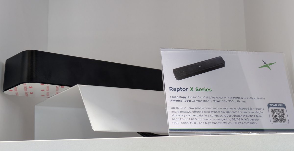
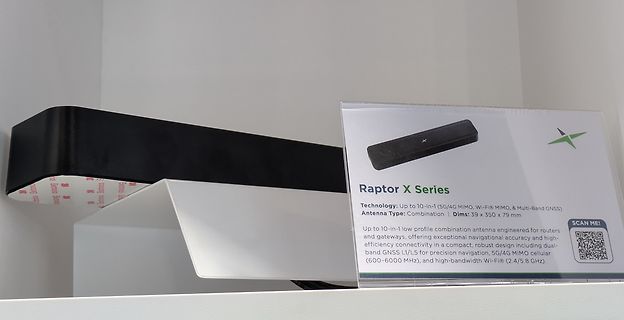
Raptor X Series Antenne und Informationsschild
Raptor X Series Technology: Up to 10-in-1 low profile combination antenna engineered for routers and gateways, offering exceptional navigational accuracy and high-efficiency connectivity in a compact, robust design including dual-band GNSS L1/L5 for precision navigation, 5G/4G MIMO cellular (600-6000 MHz), and high-bandwidth Wi-Fi (2.4/5 GHz). Antenna Type: Combination | Dims: 39 x 350 x 79 mm SCAN ME!
-
 Bild
Bild
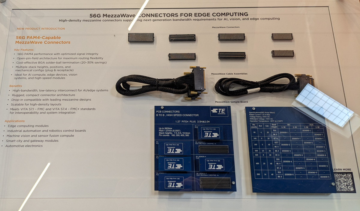
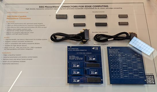
Werbeplakat für 56G MezzaWave Konnektoren
and mechanical configs (plug & receptacle) Ideal for AI compute, edge devices, vision systems, and high-speed modules. Benefits High-bandwidth, low-latency interconnect for AI/edge systems Rugged, compact connector architecture Drop-in compatible with leading mezzanine designs Scalable for high-density
-
 Bild
Bild
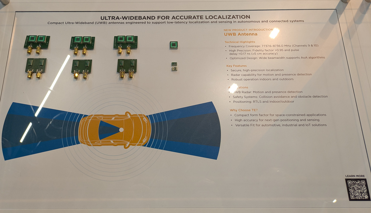
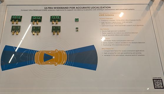
Infotafel über Ultra-Wideband Antennen
ULTRA-WIDEBAND FOR ACCURATE LOCALIZATION Compact Ultra-Wideband (UWB) antennas engineered to support low-latency localization and sensing in autonomous and connected systems NEW PRODUCT INTRODUCTION UWB Antenna Technical Highlights • Frequency Coverage: 7737.6-8736.0 MHz (Channels 9 & 10) • High Precision
-
 Bild
Bild
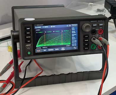
Siglent SMM312X Source Measure Unit
+0.92328 A V2: +1.501450 V ΔV: +1.003449 V Avg: +0.60480 V -0.7424 µA +2.00004 A CH2 ON Auto Scale Low High Sense ON/OFF ON/OFF 2 AUTO TRIGGER Force EXIT ENTER Graph Roll Statistics Buffer Data Logger
-
 Bild
Bild
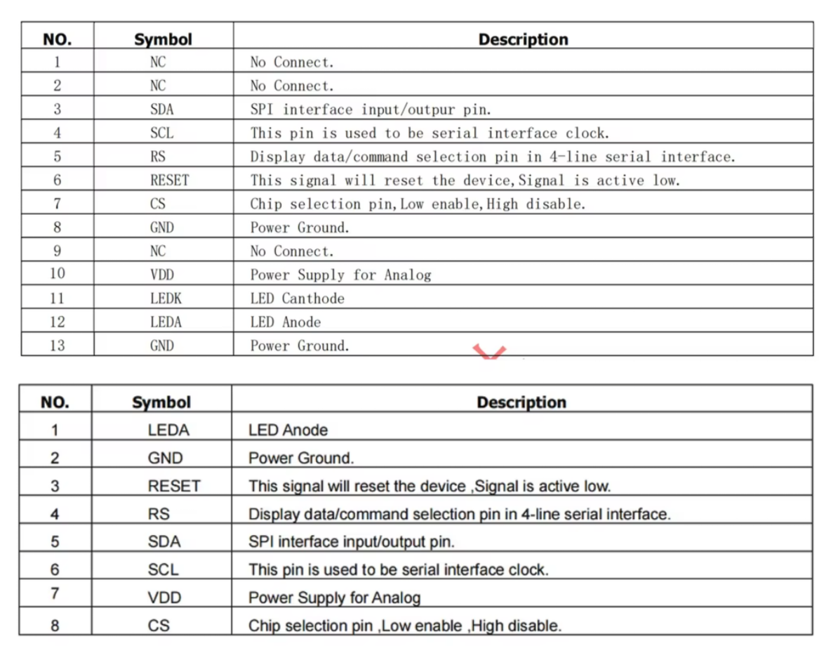
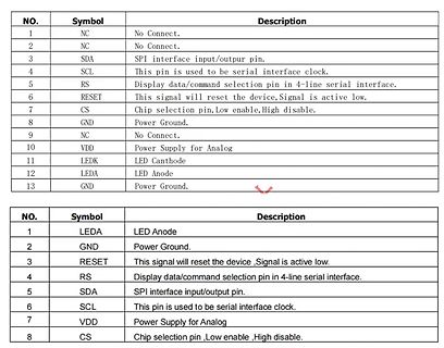
Pinbelegungslisten einer Komponente
selection pin in 4-line serial interface. 6 RESET This signal will reset the device,Signal is active low. 7 CS Chip selection pin, Low enable, High disable. 8 GND Power Ground. 9 NC No Connect. 10 VDD Power Supply for Analog 11 LEDK LED Canthode 12 LEDA LED Anode 13 GND Power Ground. NO. Symbol Description
-
 Bild
Bild
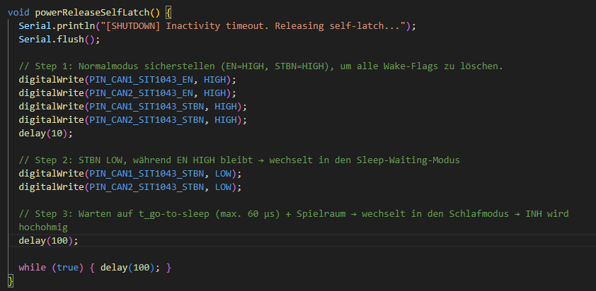
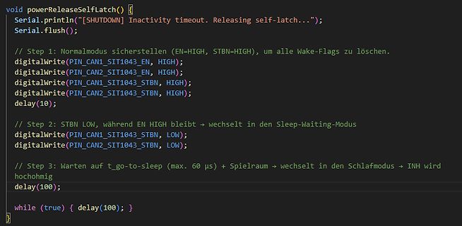
C++ Programmcode für eine Shutdown-Funktion
Inactivity timeout. Releasing self-latch..."); Serial.flush(); // Step 1: Normalmodus sicherstellen (EN=HIGH, STBN=HIGH), um alle Wake-Flags zu löschen. digitalWrite(PIN_CAN1_SIT1043_EN, HIGH); digitalWrite(PIN_CAN2_SIT1043_EN, HIGH); digitalWrite(PIN_CAN1_SIT1043_STBN, HIGH); digitalWrite(PIN_CAN2_SIT1043_STBN, HIGH); delay(10); // Step 2: STBN LOW, während EN HIGH bleibt -> wechselt in den Sleep-Waiting-Modus digitalWrite(PIN_CAN1_SIT1043_STBN, LOW); digitalWrite(PIN_CAN2_SIT1043_STBN, LOW); // Step 3: Warten
-
Thread
Selbsthaltung mit ESP32-S3 & SIT1043 schaltet nicht ab
gewünschte Verhalten: Wenn CAN-Aktivität vorliegt, befinden sich die SIT1043 im Normal-Modus, INH ist HIGH, der NPN leitet, zieht das MOSFET-Gate auf LOW und der MOSFET schaltet durch. Wenn der ESP32 2 Minuten Inaktivität erkennt, versetzt er die SIT1043 in den Sleep-Modus (EN=HIGH, STBN=LOW). INH sollte
nachmessen, auch den EN mit aus. Beim Original von NXP war das zwar theoretisch so das er da sein IHN in High Impedance setzten sollte aber das glaube ich erst wenn dann auch die VCC5 und so weg sind.
-
Thread
DCF77 Empfangsprobleme
oberen Nibble D4-D7 gefüttert werden will. Weil bei den ersten drei 30-er- Gruppen D0-D3 so wie so "low" "0" sind, ist es egal, ob das durch Portpegel oder äußere Beschaltung (Widerstände) auf GND geschieht. Das obere Nibble mit der "3" in der 30-er Gruppe wird immer von D4-D7 gelesen. Die Routine ist
"portb" statt "daten" out portb, temp ; PB0-PB3=Daten ... ori temp, 0b00010000 ; RS=high out daten,temp ; Ausgabe D4-D7-Daten-Nibble auf Port D0-D3 ... [/code] usw. Konsequent durchziehen, dann kannst du das über .equ-Änderungen auch anpassen.
-
 Bild
Bild
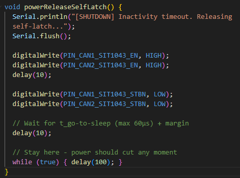
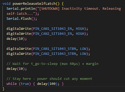
C++ Code für eine Shutdown-Funktion
Inactivity timeout. Releasing self-latch..."); Serial.flush(); digitalWrite(PIN_CAN1_SIT1043_EN, HIGH); digitalWrite(PIN_CAN2_SIT1043_EN, HIGH); delay(10); digitalWrite(PIN_CAN1_SIT1043_STBN, LOW); digitalWrite(PIN_CAN2_SIT1043_STBN, LOW); // Wait for t_go-to-sleep (max 60µs) + margin delay(10);
-
 Bild
Bild
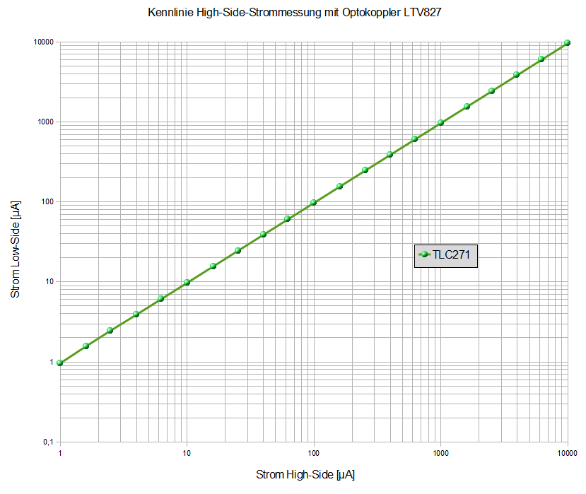
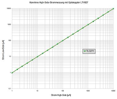
Kennlinie High-Side-Strommessung mit Optokoppler LTV827
Kennlinie High-Side-Strommessung mit Optokoppler LTV827 10000 1000 100 10 1 0,1 Strom Low-Side [µA] 1 10 100 1000 10000 Strom High-Side [µA] TLC271
-
 Bild
Bild
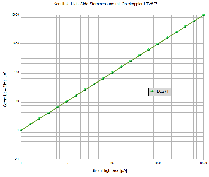
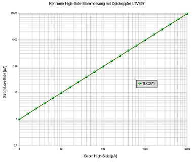
Kennlinie High-Side-Strommessung mit Optokoppler LTV827
Kennlinie High-Side-Strommessung mit Optokoppler LTV827 10000 1000 100 10 1 0,1 Strom Low-Side [µA] Strom High-Side [µA] TLC271
-
Thread
Feelin XR Pro Vape Podsystem Teardown
GPIO-Port-Basisadresse) // Bit 3 (0x08) = RESET-Pin GPIO[0x07] |= 0x08; // RESET → HIGH delay_ms(1); // FUN_00004df8(1) GPIO[0x07] &= 0xF7; // RESET → LOW (AND mit ~0x08) delay_ms(1); // FUN_00004df8(1) GPIO[0x07] |= 0x08; // RESET → HIGH delay_ms_with_check(10); // FUN_00004e34(10) // Zusätzlich: CS-Pin setzen (DAT_40040001, Bit 5 cleared via AND 0xDF) GPIO[0x01] &= 0xDF; // CS → LOW (Chip Select aktiv)
-
Thread
Isolierte Spannungsversorgung
unipolar ac is much longer compared to that under bipolar ac; it is at least two orders of magnitude higher." https://www.analog.com/media/en/technical-documentation/technical-articles/inside_icoupler_technology_high_voltage_endurance.pdf
performance * Isolation Resistance 100GΩ Aber deutlich schlechter als der RHV2 mit 4pF * Ultra low isolation capacitance 13pF Trotzdem: nimm Batterien.
-
 Bild
Bild
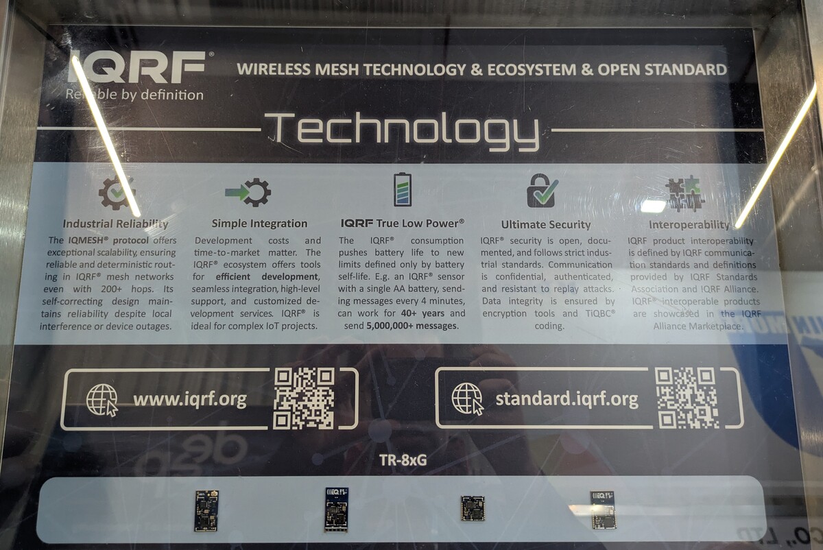
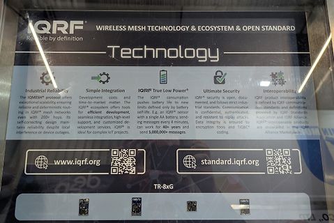
Werbeplakat für IQRF Wireless Mesh Technologie
time-to-market matter. The IQRF ecosystem offers tools for efficient development, seamless integration, high-level support, and customized development services. IQRF is ideal for complex IoT projects. IQRF True Low Power The IQRF consumption pushes battery life to new limits defined only by battery self-life
-
 Bild
Bild
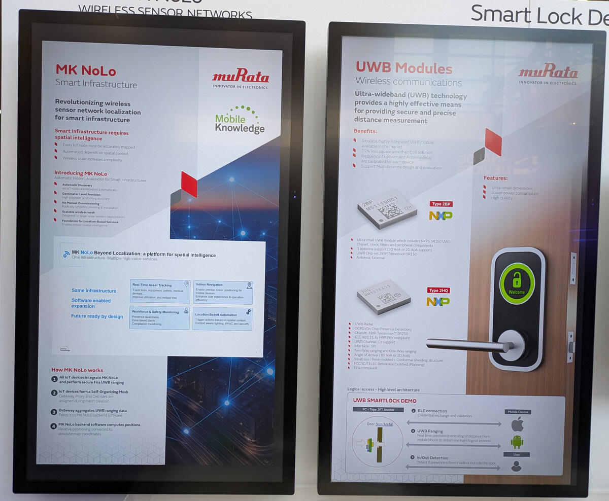
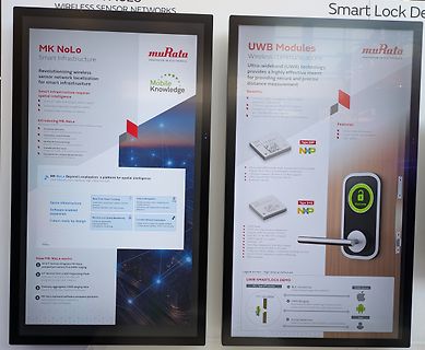
Foto von zwei Informationsdisplays zu Murata UWB Modulen
measurement. Benefits: Small/highly integrated UWB module Small footprint, less area than Col1 solution High precision, 2 antenna delay Antennas are calibrated for each device Support Multi-antenna design and evaluation Type 2BIP Type 2HIP Features: Ultra small dimensions Lower power consumption High quality MK NoLo Beyond Localization: a platform for spatial intelligence One Infrastructure. Multiple high-value services Same Infrastructure Software enabled expansion Future ready by design Real-Time Asset Tracking Inventory, equipment, people, medical devices. Navigation Indoor positioning for mobile
-
Artikel
CAN
Extended IDs. 2004 von infineon abgekündigt, ohne Nachfolgeprodukt Bustreiber (CAN-Transceiver). High-Speed. MCP2551. von Microchip PDIP8 und SOIC VCC = 4,5...5,5V kostet rund 1 Datenblatt Eagle-Lib PCA 82C250. ABGEKÜNDIGT! In Produktion: NXP Orderlist von NXP (ex. Philips) PDIP8 und SO8 VCC = 4,5..
Base Chip (SBC) SO28 Serial Interface (SPI) Spannungsregler (LDO) CAN Repeater. AMIS-42700. Dual High-Speed CAN Transceiver High speed (up to 1Mbit/s) SOIC-20 vgl. Alternative. zwei Transceiver Schaltung Anmerkung: Diese Schaltung ist Quatsch und funktioniert nicht. -Zum Senden eines Zeichen, muss beim
-
 Bild
Bild
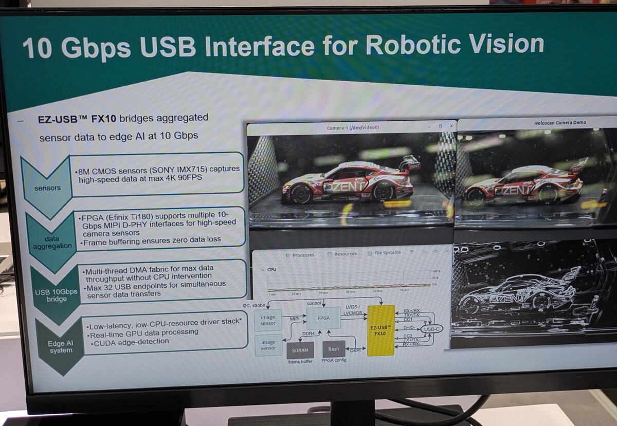
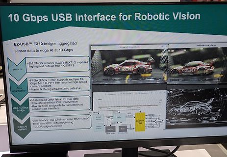
Präsentation einer 10 Gbps USB Schnittstelle für Robotic Vision
FX10 bridges aggregated sensor data to Edge AI at 10 Gbps 8M CMOS sensors (SONY IMX715) captures high-speed data at max 4K 90FPS FPGA (Efinix Ti180) supports multiple 10-Gbps MIPI D-PHY interfaces for high-speed camera sensors Frame buffering ensures zero data loss Multi-thread DMA fabric for max data throughput without CPU intervention Max 32 USB endpoints for simultaneous sensor data transfers Low-latency, low-CPU-resource driver stack Real-time GPU data processing CUDA edge-detection image sensor image sensor FPGA SDRAM flash frame buffer FPGA config I2C, strobe control LVDS / LVCMOS EZ-USB™
-
 Bild
Bild
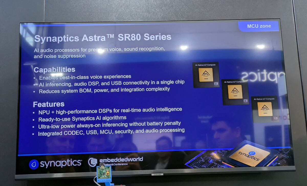
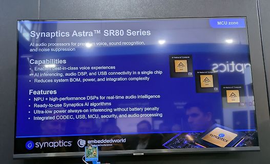
Präsentationsbildschirm für Synaptics Astra SR80 Serie
connectivity in a single chip • Reduces system BOM, power, and integration complexity Features • NPU + high-performance DSPs for real-time audio intelligence • Ready-to-use Synaptics AI algorithms • Ultra-low power always-on inferencing without battery penalty • Integrated CODEC, USB, MCU, security, and audio
-
 Bild
Bild
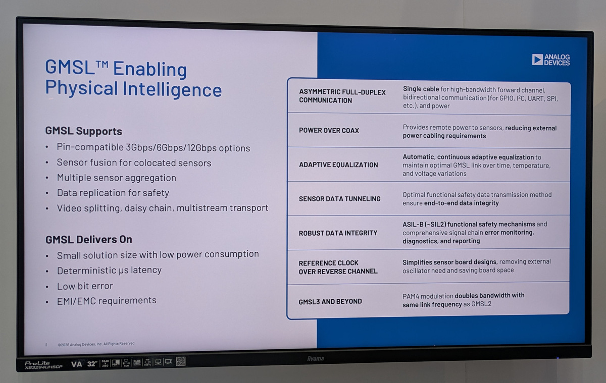
Präsentationsfolie zu GMSL Technologie von Analog Devices
safety Video splitting, daisy chain, multistream transport GMSL Delivers On Small solution size with low power consumption Deterministic µs latency Low bit error EMI/EMC requirements ANALOG DEVICES ASYMMETRIC FULL-DUPLEX COMMUNICATION Single cable for high-bandwidth forward channel, bidirectional communication
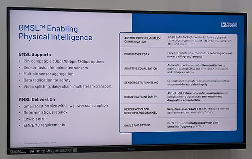
-
 Bild
Bild
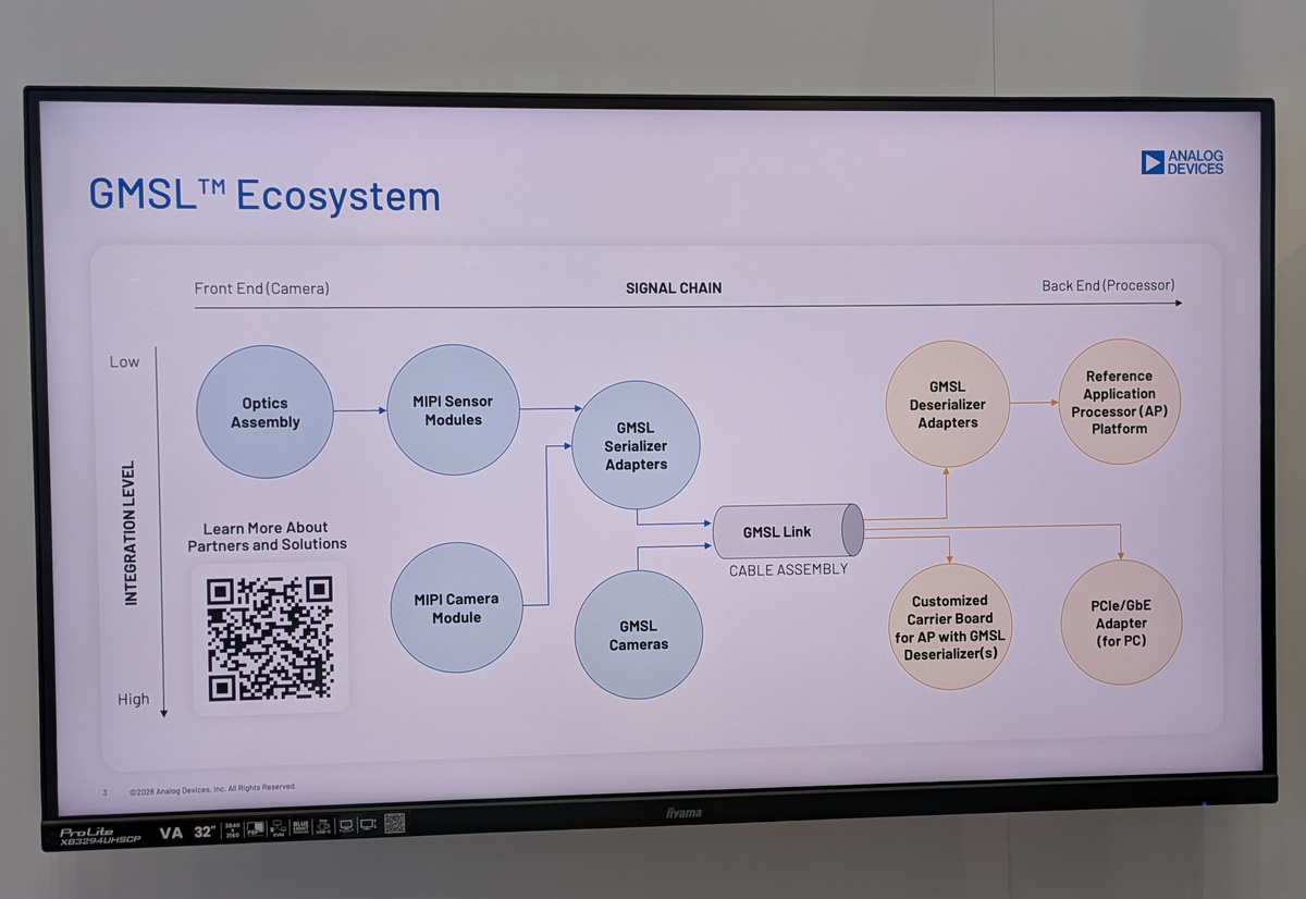
Blockschaltbild des GMSL Ecosystems auf einem Monitor
GMSL™ Ecosystem ANALOG DEVICES Front End (Camera) SIGNAL CHAIN Back End (Processor) Low Optics Assembly MIPI Sensor Modules GMSL Serializer Adapters Reference Application Processor (AP) Platform INTEGRATION LEVEL High Learn More About Partners and Solutions MIPI Camera Module GMSL Cameras
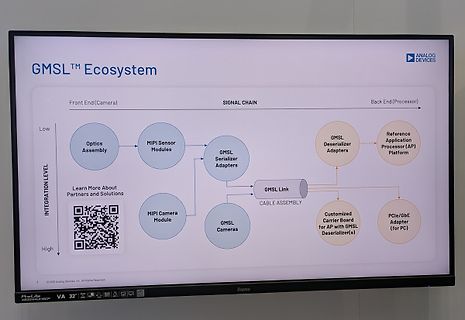
-
Thread
Low End-Mikrocontroller von Renesas und ST, Funkmodule, Amazon Sidewalk uvam
oscilloscope. Users can view all four channels simultaneously and verify proper operation at both high-speed and low-speed ARINC data rates. Output tri-state capability when powered off is also demonstrated. “The ADK-85104 provides engineers with a fast, intuitive way to evaluate all four channels
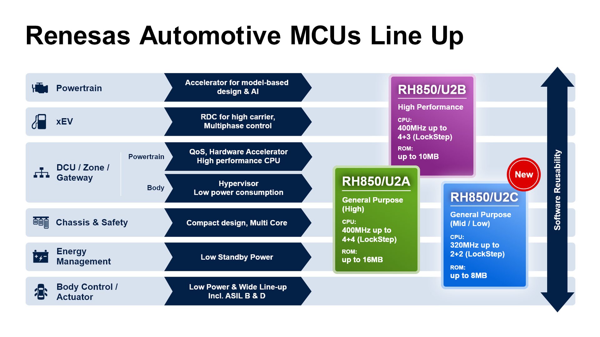
vermeldet Renesas eben da folgendes: [c] The new device extends Renesas’ popular RH850 lineup as a low-end option, complementing the high-end RH850/U2B and mid-range RH850/U2A products. The RH850/U2C combines four RH850 CPU cores operating at up to 320 MHz (including two lockstep cores), with up to 8
-
 Bild
Bild
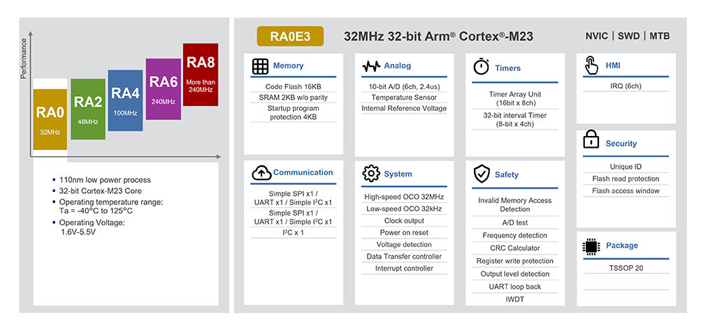
Übersicht der RA-Mikrocontroller-Serie und deren Spezifikationen
bit x 4ch) Communication Simple SPI x1 / UART x1 / I2C x1 Simple SPI x1 / UART x1 / I2C x1 System High-speed OCO 32MHz Low-speed OCO 32kHz Clock output Power on reset Voltage detection Data Transfer controller Interrupt controller HMI IRQ (6ch) Security Unique ID Flash read protection Flash access window
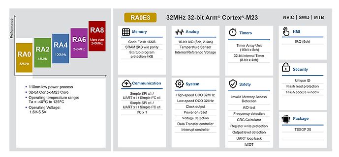
-
 Bild
Bild
Übersicht Renesas Automotive MCUs Line Up
Renesas Automotive MCUs Line Up Powertrain Accelerator for model-based design & AI xEV RDC for high carrier, Multiphase control DCU / Zone / Gateway QoS, Hardware Accelerator High performance CPU Body Hypervisor Low power consumption Chassis & Safety Compact design, Multi Core Energy Management Low Standby Power Body Control / Actuator Low Power & Wide Line-up Incl. ASIL B & D RH850/U2B High Performance CPU: 400MHz up to 4+3 (Lockstep) ROM: up to 10MB RH850/U2A General Purpose (High) CPU: 400MHz up to 4+4 (Lockstep) ROM: up to 16MB RH850
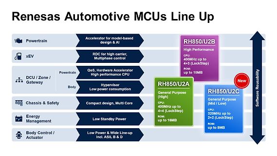
-
 Bild
Bild
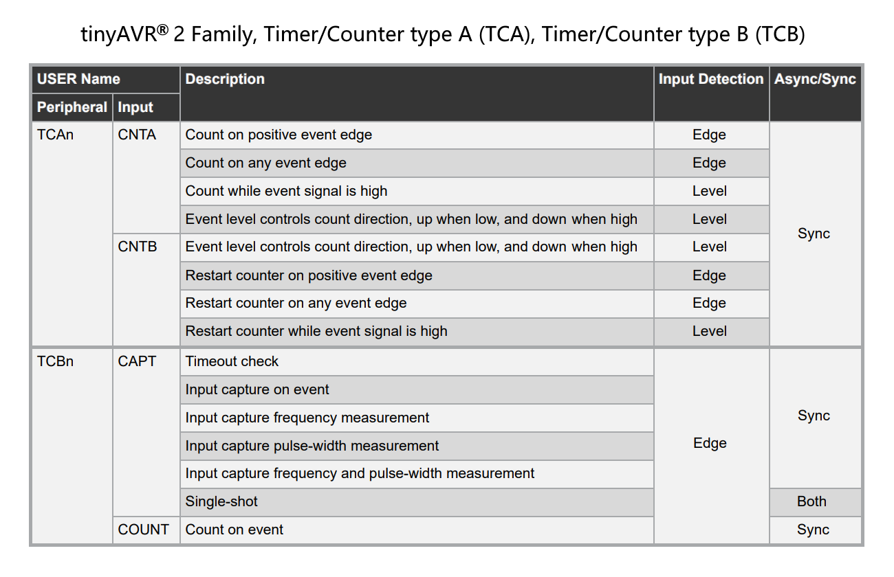
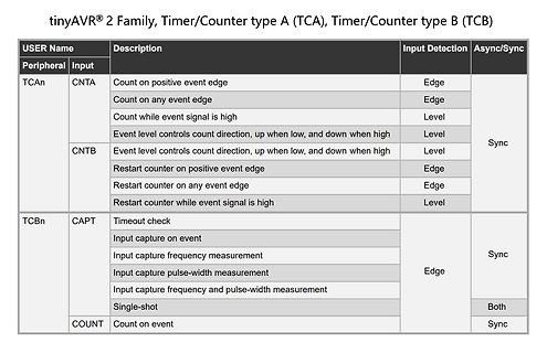
Tabelle der Timer/Counter Funktionen von tinyAVR Peripherie
TCAn CNTA Count on positive event edge Edge Count on any event edge Edge Count while event signal is high Level Event level controls count direction, up when low, and down when high Level CNTB Event level controls count direction, up when low, and down when high Level Restart counter on positive event edge Edge Restart counter on any event edge Edge Restart counter while event signal is high Level TCBn CAPT Timeout check Sync Input capture on event Edge Input capture frequency measurement Edge Input capture pulse-width measurement Edge Input capture frequency and pulse-width measurement
-
Thread
Debounce von Tasten mit dem Candidate-Pattern (Platformunabhängig, Theorie)
--------------------------- Beispiel eines prellenden Signals: [pre] Rohsignal (Bounce) HIGH ────────┐ ┌─┐ ┌──┐ ┌─┐ │ │ │ │ │ │ │ LOW ─────────┴───┘ └─┘ └─┘ └──────── Zeit → [/pre] Der Mikrocontroller würde mehrere Flanken erkennen, obwohl der Benutzer nur *einmal
eingeschoben. Nehmen wir einen Takt von 1KHz an. Bei der Folge "11111110" wird das Signal nach 1ms als Low erkannt, musste aber vorher für mindestens 7ms High sein. Bei der Folge "11110000" muss das Signal 4ms High und danach 4ms Low sein. Kritisch deshalb weil es passieren kann, dass so ein Muster gar
-
Thread
Mini Loopantenne mit NE592N14
bisschen das L messen und anpassen, wenn man die Möglichkeit hat. Bei unkritischen Anwendungen und Low Level kommt das nicht so furchtbar genau. Ich betone 'unkritisch'; z.B. kein High Power! Leitungstransformatoren (*) sind meist sehr geduldige Zeitgenossen. 73 Wilhelm (*) Hier fehlt kein 's
tested most of the transistor types I have on hand that could be suitable for use in an RF preamp (low impedance loop amp or 50 ohm amp). It turns out that both tests track each other quite well--that is, a transistor with low noise output at LF also has a low noise figure at 10 MHz. I've given the results
-
Thread
Funktionsweise CAN <-> LWL <-> CAN
Benutzerhandbuch schaut bekommt man einige Hinweise zur Funktion, z.B. gibt es jeweils zwei CAN Transceiver (Low-/High-Speed, maximal 500 kBit/s bei High-Speed) von denen man einen auswählen muss und die Verbindung zwischen den beiden Modulen erfolgt durch zwei Lichtwellenleiter.
die fehlende Verzögerung die Ursache für das Schwingen ist? Die Logik setzt ja nur den Pegel auf High, wenn von beiden Seiten gesendet wird.
-
Thread
Ladezustand Elektroauto (Typ2 Ladung)
relevante Kommunikation passiert über den CP Pin im Ladestecker. Dabei gibt es zwei Mechanismen. Low-Level Kommunikation: Die Ladesäule signalisiert über den Dutycycle eines PWM-Signals den maximal möglichen Ladestrom bzw. die Verwendung der Highlevel-Kommunikation. Das Fahrzeug ändert durch das Zuschalten eines Widerstands den Spannungspegel am CP Pin und signalisiert so seine Ladebereitschaft. High-Level Kommunikation: Ethernetpakete werden per Powerlinekommunikation auf den CP Pin zusätzlich aufmoduliert. Auch moderne AC-Wallboxen können damit gemäß ISO 15118 den Ladezustand des Fahrzeugs auslesen
-
Thread
Erratum gegen ESP32-C5, neue Messtechnik und Erfolge für RISC/V
testing MF/HF/VHF/UHF antennas, including Shortwave, Wi-Fi, Bluetooth, and GPS applications. 7-Inch High-Definition Capacitive Touchscreen:Features a large 7-inch IPS LCD display with a resolution of 1024x600 and capacitive touch control. The bright screen ensures clear visibility even in outdoor environments
auch auf Mikrocontroller anwenden... Einen Mikrocontroller zu entwickeln der alles kann (5V Betrieb, High Performance, Lower Power, Industriesteuerung, Multimedia, ...) macht keinen Sinn und ist auch überhaupt nicht möglich. Daher gibt's jede Menge verschiedene. Viele davon haben aber gemeinsame Funktionsblöcke
-
Thread
Vor paar Jahren konnten die Burschen kaum laufen Gesperrt
kaufen könnten. Ziemlich hohes Ross für eine Nation die sich zwischen unterwürfigem Betteln nach high tech und Abschottung gegen den Untergang des eigenen Industriemuseums befindet. Und da jetzt wieder 'das ist alles subventioniert' kommt: Subventionen regen uns nur dann auf wenn ein anderer das
Michael K. schrieb im Beitrag #8019201: > China ist längst eine high tech Nation. Bestenfalls Teile von China. Aber auch wird noch ordentlich vom Ausland eingekauft und kopiert. Eigene Innovation ist eher rar. > Und da jetzt wieder 'das ist alles subventioniert