von der Komplexität noch erträglich. In dem Fall hier war das vorteilhaft, weil der control-transfer testweise schnell eingebaut war, und mein Framework die per-Geräte Verbindungseinstellungsumschaltung ohnehin kann :) die software wird übrigens irgendwann mal open-source werden...nach einem größeren
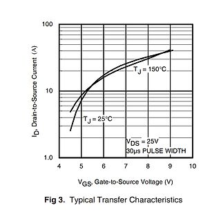
V DD ) d ( E A L V T P U O ,u Vo 0 0 V T- VT+ VDD VH Vin INPUT VOLTAGE (Vdc) Figure 3. Typical Transfer Characteristics http://onsemi.com 4 MC14584B PACKAGE DIMENSIONS PDIP−14 P SUFFIX CASE 646−06 ISSUE N NOTES: 1. DIMENSIONING AND TOLERANCING 14 8 PER ANSI Y14.5M, 1982. 2. CONTROLLING DIMENSION: INCH
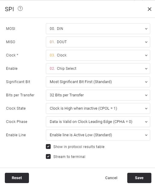
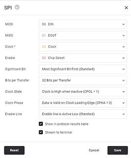
03. Clock
Enable 02. Chip Select
Significant Bit Most Significant Bit First (Standard)
Bits per Transfer 32 Bits per Transfer
Clock State Clock is High when inactive (CPOL = 1)
Clock Phase Data is Valid on Clock Leading Edge (CPHA = 0)
Enable Line Enable line is Active Low (Standard)
Show in protocol
below parameters :
Search (Ctrl+F)
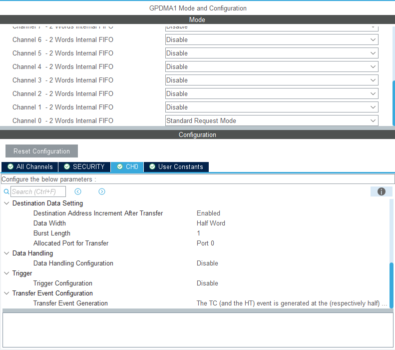
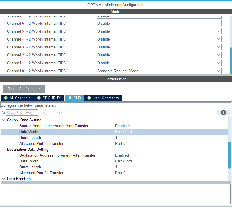
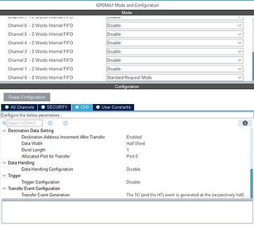
Destination Data Setting
Destination Address Increment After Transfer Enabled
Data Width Half Word
Burst Length 1
Allocated Port for Transfer Port 0
Data Handling
Data Handling Configuration Disable
Trigger
Trigger Configuration Disable
Transfer Event Configuration
Transfer Event Generation The TC (and the HT) event is generated at the (respectively half) ...
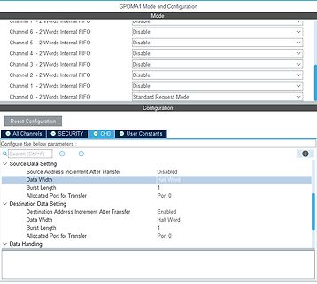
Configure the below parameters :
Search (Ctrl+F)
Source Data Setting
Source Address Increment After Transfer Disabled
Data Width Half Word
Burst Length 1
Allocated Port for Transfer Port 0
Destination Data Setting
Destination Address Increment After Transfer Enabled
Data Width Half Word
Burst Length 1
Allocated Port for Transfer Port 0
Data Handling
broadband noise into the baseband. Similarly for CDS, there is a zero at the origin for the baseband transfer function that cancels any DC offset and significantly reduces the 1/f noise. However, the folded components will be scaled by different but comparable transfer functions to those described in the
neuen Werte in das Shadow-Compare-Register CRS noch mit dem entsprechendem Bit im Register GCSS der Transfer gestartet werden muss. In der CC4x.c kommt zudem das RTX zum Einsatz. Mit dem RTX wird die dim_task gestartet. Deren Endlos-Schleife läuft mit einem konstanten Takt von 50ms. Im Demo Modus - wenn
a positive supply via a pull-up resistor when connected to the output stages of a device. Data transfer may be initiated only when the bus is not busy. 7.1 Bit transfer One data bit is transferred during each clock pulse. The data on the SDA line must remain stable during the HIGH period of the clock
data is written to the the High Voltage operational state. High Voltage MCP4XXX after every byte transfer (during the commands allow the device’s WiperLock Technology Acknowledge). If a Stop or Restart condition is gener- ated during a data transfer (before the A), the data will and write protect features
aus einer App heraus direkt auf USB-Geräte zugreifen, ähnlich zu libusb, und dann beliebige USB-Transfer machen. Das läuft über die UsbManager-Klasse. Der User muss dies nur 1x erlauben (kein rooten o.ä. erforderlich). Ein USB-UART-Chip wird sowieso nicht im Budget sein, man muss auf dem Mikrocontroller
of SDCC warning uint8_t len = 0; // todo this just works for descriptor sets < 256 bytes if(UIF_TRANSFER) { // transfer interrupt switch (USB_INT_ST & (MASK_UIS_TOKEN | MASK_UIS_ENDP)) { // // todo place here bulkrequests for CDC // case UIS_TOKEN_SETUP | 0: { // handle setup stage UEP0_CTRL &= 0xF2;
Verschenke diese Tonertransferfolie. Habe selber nur wenig benutzt und sie liegt seit längerem ungenutzt rum. Porto müsste 1,60€ sein glaube ich. Gruss
9-bit) uses three pins(CSB、SDA、SCK) to enter commands and data. Timing sequence is shown below. Transfer command mode: Transfer data mode: Note: 1、the RS bit defines whether the following data bytes are interpreted as COMMAND or as DATA: When RS is “low”, the following data is COMMAND. When RS is “high
anschließen. Ob es jetzt ein CNY17 oder ein 4N35 ist, kann ich nicht sagen, aber den CTR-Wert (Current Transfer Ratio) kannst du selber herausbekommen und dann einen Ersatztyp mit der entsprechenden Stromverstärkung verwenden. 820 kann auch das Datum sein: Jahr 2008 und 20ste Woche.
> Ob es jetzt ein CNY17 oder ein 4N35 ist, kann ich nicht sagen, aber den > CTR-Wert (Current Transfer Ratio) kannst du selber herausbekommen und > dann einen Ersatztyp mit der entsprechenden Stromverstärkung verwenden. Ich werde bei Gelegenheit mal das Zeitverhalten testen (Rechtecksignal an die
the I C lines. (For further details, refer to I C pull-up Resistor Calculation (SLVA689).) Data transfer may be initiated only when the bus is idle. A bus is considered idle if both SDA and SCL lines are high after a STOP condition. The following is the general procedure for a master to access a slave
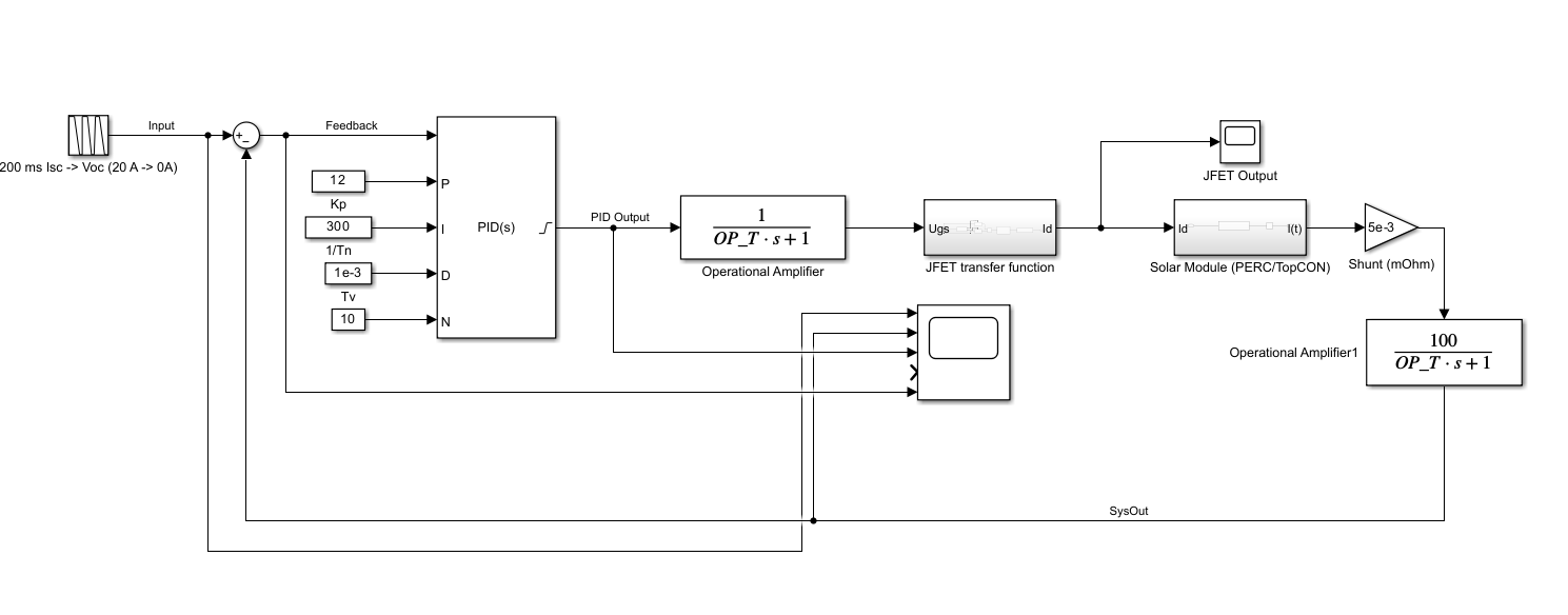
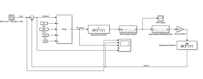
Kp 300 I 1/Tn 1e-3 Tv 10 N PID(s) PID Output 1 / (OP_T * s + 1) Operational Amplifier Ugs JFET transfer function Id Solar Module (PERC/TopCON) Id I(t) Shunt (mOhm) 100 / (OP_T * s + 1) Operational Amplifier1 SysOut
.....................................................................................13 4.3.8.2 Transfer initiated by the key manager...................................................................................................13 4.3.8.3 Transfer initiated by the key consumer....................
Pulse. In this case, the master transmitter can generate the STOP Information in order to abort the transfer. TRANSMISSION WITHOUT ACKNOWLEDGE If you want to avoid the acknowledge detection of the audio processor, a simpler µP transmission may be used. Wait one clock and does not check the slave acknowledge
zu ermitteln. Bild: Kleine Frequenzen sind falsch, da Zeitbereich nur 600µs [code] G = TransferFunction{Continuous, ControlSystemsBase.SisoRational{Float64}} -1.4825867447070777s^2 + 3.915381717456055e7s - 4.5138075195136e14 -------------------------------------------------------------
Derivative aus MODELICA hat noch ein T - sonst geht es nicht. [code] This blocks defines the transfer function between the input u and the output y as approximated derivative: k * s y = ------------ * u T * s + 1 [/code]
per coil at -40°C to +20 C temperature ambient 0,30 W per coil at +80°C temperature ambient Disc transfer time 100ms (stopped disc) 1,5s (unstopped disc) (IA= 350mA, T = i ms, current drive) Lifetime 200 millions disc turns over Display colors disc set-color yellow (white, red, green ... on demand
MCU::ETHERNET::DMA::OMR, 26); // Store-and-Forward Mode (means, that the DMA will only start to transfer the Frame from/to the MAC when the complete Frame is received/sent) bit::set(*MCU::ETHERNET::DMA::OMR, 21); bit::set(*MCU::ETHERNET::DMA::OMR, 25); // Set Full-Duplex Mode bit::set(*MCU::ETHERNET:
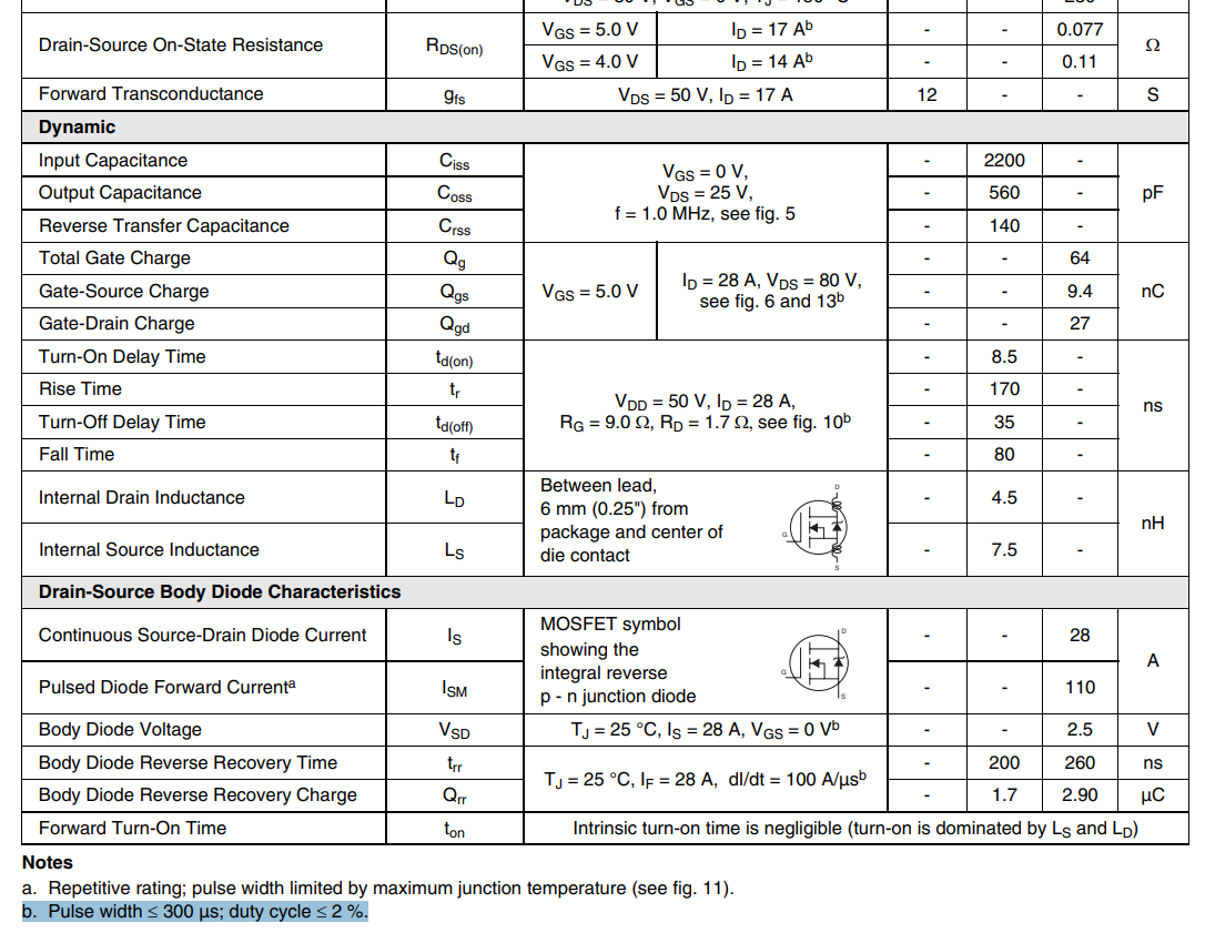
Characteristics Input Capacitance C iss - 6300 - VDS1000V - 260 pF Output Capacitance Coss - VGS =0V Reverse Transfer Capacitance C rss Freq.=100kHz - 16 - C ossStored Energy Eoss - 150 - μJ Turn-On Switching Energy E on VDS800V,V GS=-4V/+15V - 1380 - ID=80A,R G(ext).0Ω μJ Turn-Off Switching Energy E off L=100μH
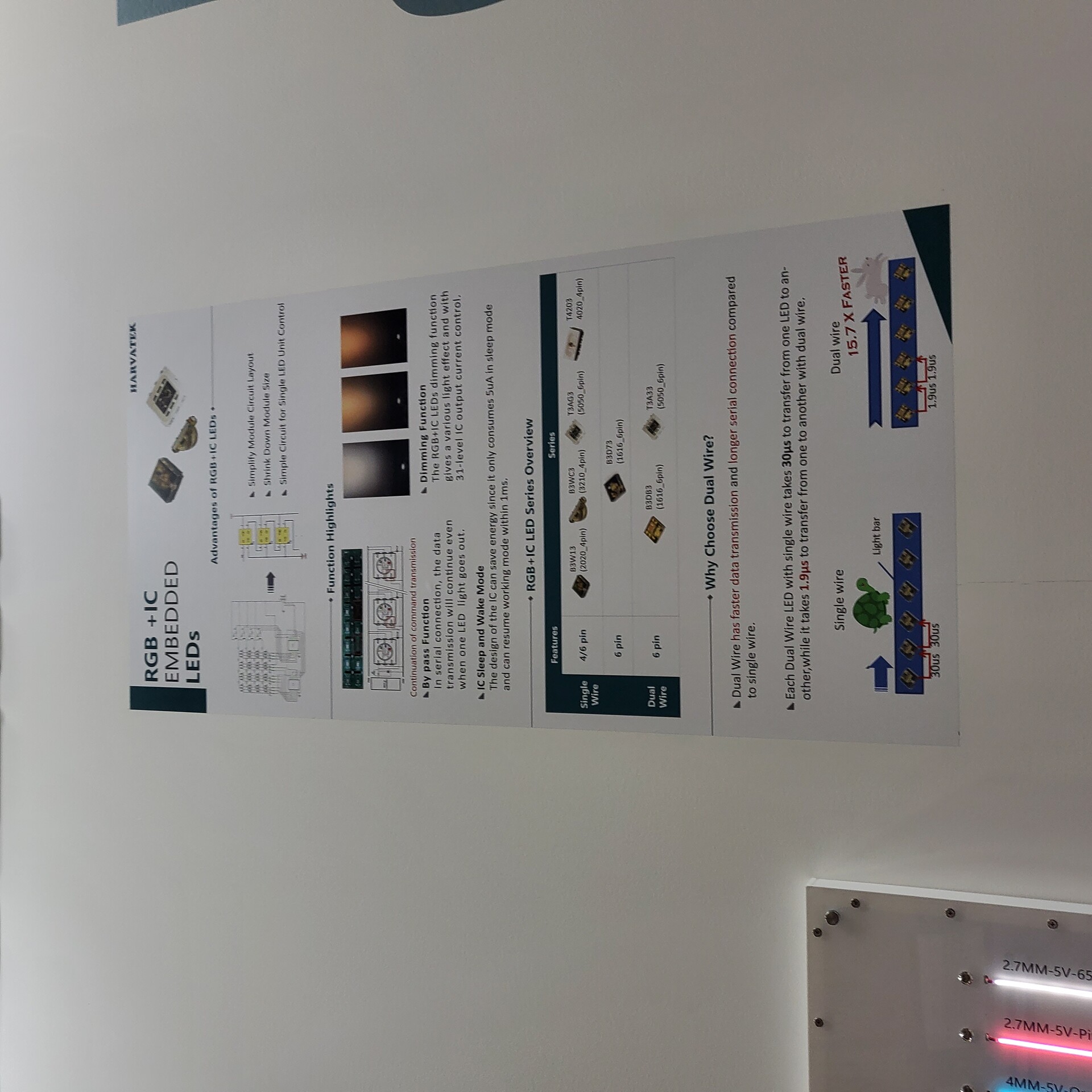
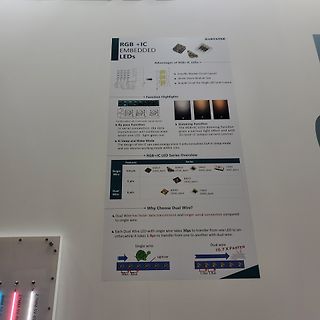
longer serial connection compared to single wire.
Each Dual Wire with single wire takes 30us to transfer from one LED to another, while it takes 1.9us to transfer from one to another with dual wire.
Single wire 30us 30us
Light bar
Dual wire 1.9us 1.9us
15.7 X FASTER
darauf hat. Kann es vorkommen, dass vom Tester während dieser conductive-frames schickt (z.B. bei Transfer-Data), zwischendrinn ein Tester-Present als request schickt? Oder muss ein gestarteter Request erst bis zum ende gesendet werden? In der ISO konnte ich so einen fall nirgends finden.
Timer aufzieht, ohne übers ISOTP/UDS laufen zu müssen, weil das ja gerade mit einem segmentierten Transfer beschäftigt sein könnte.
SCLK, SIN, XLAT pin –1 1 I Input current VI= GND; MODE pin –1 1 A V = V ; MODE pin 50 I CC No data transfer, all output OFFO V = 1 V,(IREF) 10 kΩ 0.9 6 No data transfer, all output OFFO V = 1 V,(IREF) 1.3 kΩ 5.2 12 CC Supply current mA Data transfer 30 MHz, all output ON,OV = 1 V, (IREF) 1.3 kΩ 16 25 Data transfer 30 MHz, all output ON, V = 1 V, R = 640 Ω 30 60 O (IREF) O(LC) Constant output current All output ON, O = 1 V, R(IREF) 640 Ω 54 61 69 mA lkg Leakage output current All output OFF, O = 15 V, R(IREF
The system controller sets SDIO = 1, indicated by NACK = 1, to signal to the device the 2-wire transfer will end. The system controller should set the STOP condition. This process is repeated until the STATUS byte indicates that CTS bit is set, 0x80 in this example. START ADDR+R ACK STATUS NACK STOP
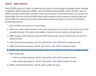
Machine
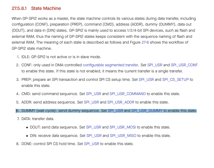
When GP-SPI2 works as a master, the state machine controls its various states during data transfer, including configuration (CONF), preparation (PREP), command (CMD), address (ADDR), dummy (DUMMY), data out (DOUT), and data in (DIN) states. GP-SPI2 is mainly used to access 1/2/4-bit SPI devices
002 02 ! 3 00000011 003 03 ! 4 00000100 004 04 ! 5 00000101 005 05 ! 6 00000110 006 06 TAP AF 1 2 Transfer A to Status Flag Register 7 00000111 007 07 TPA A,Flags 1 2 Transfer Status Flag Register to A 8 00001000 010 08 INX Index 1 4 Increment the Index Register 9 00001001 011 09 DEX X 1 4 Decrement the
of these bits is the configured SPI transmission data bit length in master mode DMA controlled transfer or CPU controlled transfer. The value is also the configured bit length in slave mode DMA RX controlled transfer. The register value shall be (bit_num-1). Can be configured in CONF state.*/ uint32
Frank E. schrieb im Beitrag #7772106: > Naja, "viel" ist relativ: Faktor ca. 1,4. Mit Transfer-Encoding: gzip sogar weniger. Allerdings hat der Webbrowser dann weniger Möglichkeit zum Cachen. Der TE will wohl eine statische HTML-Datei auf die Festplatte schreiben, von einem Webserver war
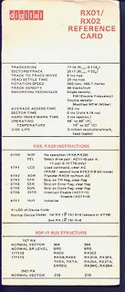
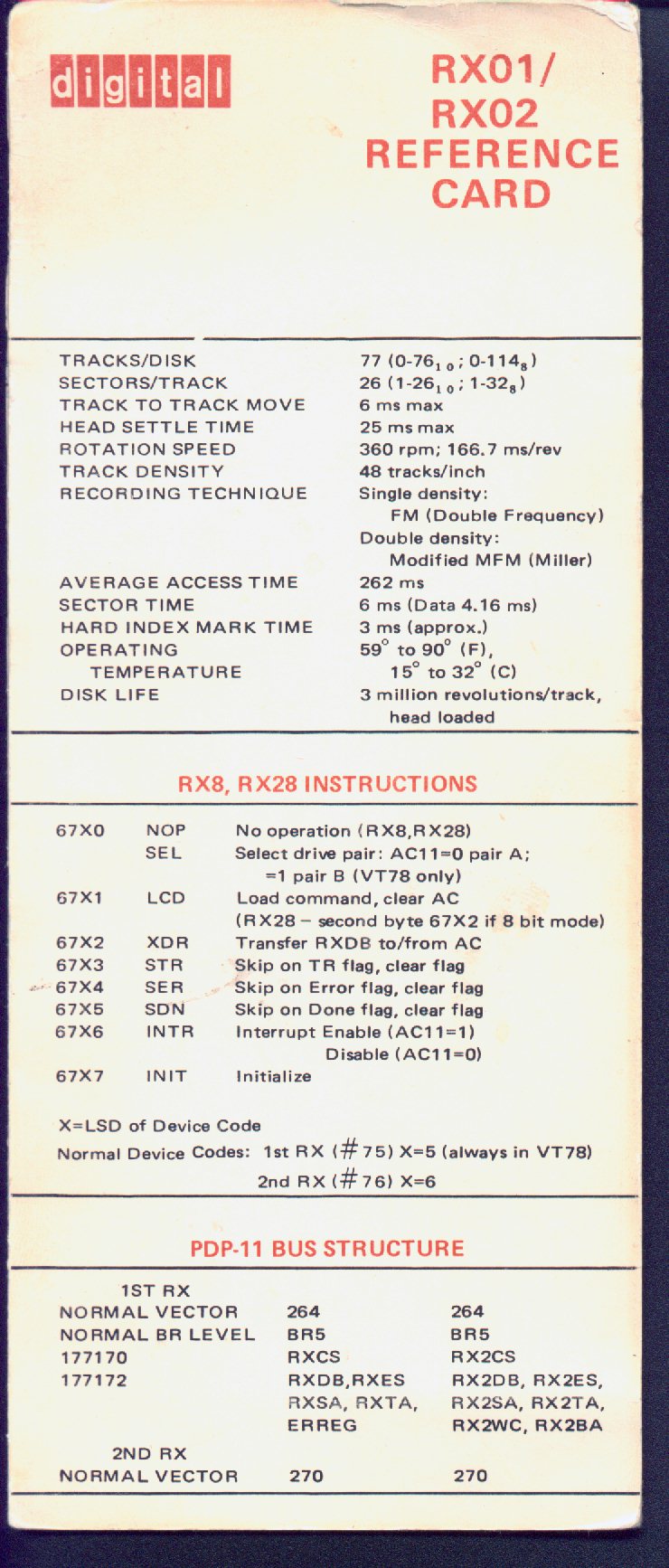
B (VT78 only) 67X2 LCD Load command, clear AC (RX28 - second byte 67X2 if 8 bit mode) 67X3 XDR Transfer RXDB to/from AC 67X4 STR Skip on TR flag, clear flag 67X5 SER Skip on Error flag, clear flag 67X6 SDN Skip on Done flag, clear flag 67X7 INTR Interrupt Enable (AC11=1) Disable (AC11=0) X=LSD of Device
bit or 16-bit bus width, and three (3) Designers can either use parallel bus to achieve high data transfer rate, or use serial bus to create compact LCD modules. Bus Type 8080 6800 S8 (4wr) S8uc(3/4wr) S9 (3WR) Access 16-bit 8-Read/Writebit 8-bit Write Only BM[1:0] 10 00 11 01 00 00 01 {DB[15], DB[13]}
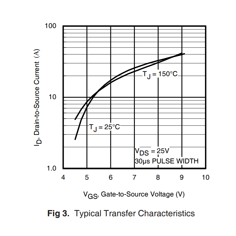
contact S C Input Capacitance 3400 V = 0V iss GS Coss Output Capacitance 1400 pF VDS = -25V C Reverse Transfer Capacitance 640 = 1.0MHz, See Fig. 5 rss Source-Drain Ratings and Characteristics Parameter Min. Typ. Max. Units Conditions I Continuous Source Current MOSFETsymbol D S -74 (Body Diode) A showing
Data Modes 591 27.5.2 FSPI Bus Signal Mapping 592 27.5.3 Bit Read/Write Order Control 594 27.5.4 Transfer Modes 594 27.5.5 CPU-Controlled Data Transfer 594 27.5.5.1 CPU-Controlled Master Mode 595 27.5.5.2 CPU-Controlled Slave Mode 596 27.5.6 DMA-Controlled Data Transfer 596 27.5.6.1 GDMA Configuration
TEST_UTF8 != 0) && (EVE_GEN > 2) /* we need a BT81x for this */ #if 0 /* this is only needed once to transfer the flash-image to the external flash */ uint32_t datasize; EVE_cmd_inflate(0, flash, sizeof(flash)); /* de-compress flash-image to RAM_G */ datasize = EVE_cmd_getptr(); /* we unpacked to RAM_G address
schon seit einigen Jahren die 10 bis 15 Deckel FP Maschinen im befreundeten Betrieb. Zum Datei Transfer kann ich Dir folgendes empfehlen: Adapter: USB zu seriell Adapter (9-pol male Ausgang) Kabel: Standard serielles Kabel 9-pol(female) auf 25-pol(male) Die Bedienkonsole der D4 Maschinen hat ja unten
Characteristics Input Capacitance C iss V DS0V - 560 - Output Capacitance Coss VGS0V - 40.6 - pF Reverse Transfer Capacitance C rss f=1.0MHZ - 30.9 - Switching Characteristics Turn-on Delay Time d(on) - 10.5 - V DD0V, V =1GS Turn-on Rise Time tr R =3.3, I =3A - 9.3 - ns Turn-off Delay Time t G D - 35.7 - d(off
a positive supply via a pull-up resistor when connected to the output stages of a device. Data transfer may be initiated only when the bus is not busy. 7.1 Bit transfer One data bit is transferred during each clock pulse. The data on the SDA line must remain stable during the HIGH period of the clock

 Bild
Bild
 Bild
Bild
 Bild
Bild
 Bild
Bild
 Bild
Bild
 Bild
Bild
 Bild
Bild
 Bild
Bild
 Bild
Bild