-
PDF
IRF3205Z.pdf
Capacitance ––– 310 ––– pF ƒ = 1.0MHz Coss Output Capacitance ––– 1940 ––– V = 0V, V = 1.0V, ƒ = 1.0MHz GS DS Coss Output Capacitance ––– 430 ––– VGS= 0V, V DS= 44V, ƒ = 1.0MHz Cosseff. Effective Output Capacitance ––– 640 ––– VGS= 0V, VDS= 0V to 44V f Source-Drain Ratings and Characteristics Parameter Min.
in „Geiger Counter Sparkfun“ · Mikrocontroller und Digitale Elektronik ·
-
PDF
CFAG12864BTFHV_v3.0.pdf
Oscillation Frequency H OSC=430kHz L OSC=215kHz In the slave mode, it is connected to V . DD Duty Selection (DS1, DS2) It provides various duty selections according to DS1 and DS2. DS1 DS2 Duty L 1/48 L H 1/64 H L 1/96 H 1/128 Neotec Semiconductor Ltd. 11/19 NT7107DSRev0.3 20060607 www.neotec.com.tw Appendix Neotec
in „avr asm LCD Problem“ · Mikrocontroller und Digitale Elektronik ·
-
PDF
mt9v403_ds.pdf
Technology, Inc., reserves the right to change products or specifications without notice. MT9V403_DS.fm - Rev. B 1/04 EN 14 ©2004 Micron Technology. Inc. 1/2-INCH VGA (WITH FREEZE-FRAME) CMOS ACTIVE-PIXEL DIGITAL IMAGE SENSOR Registers Table 4: Complete Register Description READ/ WRITE REGISTER REGISTER
in „Wer hat Interesse an CMOS Bildsensoren?“ · Mikrocontroller und Digitale Elektronik ·
-
PDF
DS1302.pdf
8-pin SOICs for surface X2 3 6 I/O GND 4 5 RST mount § Simple 3-wire interface DS1302 8-Pin SOIC (200-mil) § TTL-compatible (V CC = 5V) DS1302 8-Pin SOIC (150-mil) § Optional industrial temperature range: -40°C to +85°C V CC2 1 16 V CC1 § DS1202 compatible NC 2 15 NC X1 3 14 SCLK
in „genauer TIMER“ · Mikrocontroller und Digitale Elektronik ·
-
PDF
DS1302.pdf
8-pin SOICs for surface X2 3 6 I/O GND 4 5 RST mount § Simple 3-wire interface DS1302 8-Pin SOIC (200-mil) § TTL-compatible (V CC = 5V) DS1302 8-Pin SOIC (150-mil) § Optional industrial temperature range: -40°C to +85°C V CC2 1 16 V CC1 § DS1202 compatible NC 2 15 NC X1 3 14 SCLK
in „RTC DS 1302“ · Mikrocontroller und Digitale Elektronik ·
-
PDF
EEPROM.pdf
web site at www.microchip.com. FIGURE 1-1: BUS TIMING DATA 5 2 D4 4 SCL 7 3 8 9 10 SDA 6 IN 16 13 14 SDA OUT WP (protected) 11 12 (unprotected) DS21203N-page 4 © 2005 Microchip Technology Inc. 24AA256/24LC256/24FC256 2.0 PIN DESCRIPTIONS The descriptions of the pins are listed in Table 2-1. TABLE 2-
in „EEPROM auslesen (24xx256) mit Pic16f819, an PC über RS232“ · Mikrocontroller und Digitale Elektronik ·
-
PDF
PIC18F46J11_39932D.pdf
device’s Reset vector. 13. Determine if the device exited Deep Sleep by reading the Deep Sleep bit, DS (WDTCON<3>). This bit will be set if there was an exit from Deep Sleep mode. 14. Clear the Deep Sleep bit, DS (WDTCON<3>). 15. Determine the wake-up source by reading the DSWAKEH and DSWAKEL registers
in „PIC18F46J11 und RTC. Quarz nötig? Anfängerfrage Übersicht verloren ;-(“ · Mikrocontroller und Digitale Elektronik ·
-
PDF
tc4420.pdf
T56 T 100 10V n30 N E 5V ( t R R M D1 R42 U T U C Y20 C 500 kHz Y A L28 P 10 E P P D U 200 kHz S 10 S14 20 kHz 0 0 0 –60 –20 20 60 100 140 0 100 1000 10,000 0 100 1000 10,000 T (°C) CAPACITIVE LOAD (pF) FREQUENCY (kHz) A TC4420/9-6 10/18/96 © 2001 Microchip TechnolDS21419A 4 6A HIGH-SPEED MOSFET DRIVERS
in „Mosfet Driver gesucht“ · Mikrocontroller und Digitale Elektronik ·
-
PDF
APM2601.pdf
Symbol Parameter Test Condition Unit Min. Typ. Max. Static Drain-Source Breakdown BV DSS V GSV , I DS250µA -20 V Voltage Zero Gate Voltage Drain DSS Current V DS-16V , VGS0V -1 µA VGS(th) Gate Threshold Voltage V DSV GS ,DS =-250µA -0.45 -1.2 V I Gate Leakage Current V =±8V , V =0V ±100 nA GSS GS DS
in „SMD-Bauteilbestimmung“ · Mikrocontroller und Digitale Elektronik ·
-
PDF
___MPASM_USER_S_GUIDE_with_MPLINK_and_MPLIB.pdf
listing file. m On Enable/Disable macro expansion o Off Enable/Disable/Set Path for the object file. DS33014F - page 14 1997 Microchip Technology Inc. Chapter 2. P a r Table 2.1 Assembler Command Line Options (Continued) t 1 p None Set the processor type: – /p<processor_type> M where <processor_type>
in „Anfängerfrage zu Assembler“ · Mikrocontroller und Digitale Elektronik ·
-
Datei
Drehzahl-ST.asm
wr0 ; IRQ bei k = 1/2 * fpwm ldi drehzahl, dz ; nur bei 1 MHZ !!! ; Prescaler = 128 ; Fclk/128 -> DS S.119 T46, Phase Correctly PWM - ein DS. S.117 T42 ; OC2 pin 14 PB3 - LOW = Match->TOP->Match -DS. S118 T45 und PD5 = LOW -> rechts ldi wr0, 0x65 ; 01100101 out TCCR2, wr0 ; ; Timer0/Counter0 einstellen
in „Motorentreiber L293D“ · Analoge Elektronik und Schaltungstechnik ·
-
PDF
162399-da-01-en-IRF_4905.pdf
Normalized On-Resistance Vs. Temperature IRF4905 7000 20 VGS = 0V, f = 1MHz ID = -38A Ciss = C gs + Cgd , C ds SHORTED ) 6000 Crss = C gd V C = C + C ( VDS = -44V oss ds gd g16 V = -28V ) t DS F 5000 o ( C iss V e e c 4000 r12 a u c C oss o a - p 3000 t C e 8 , a C 2000 G C rss , S 4 V 1000 - FOR TEST CIRCUIT
in „High Side Switch“ · Mikrocontroller und Digitale Elektronik ·
-
PDF
IRF4905_TO220.pdf
Normalized On-Resistance Vs. Temperature IRF4905 7000 20 VGS = 0V, f = 1MHz ID = -38A Ciss = C gs + Cgd , C ds SHORTED ) 6000 Crss = C gd V C = C + C ( VDS = -44V oss ds gd g16 V = -28V ) t DS F 5000 o ( C iss V e e c 4000 r12 a u c C oss o a - p 3000 t C e 8 , a C 2000 G C rss , S 4 V 1000 - FOR TEST CIRCUIT
in „FET Frage (n oder p)“ · Analoge Elektronik und Schaltungstechnik ·
-
PDF
Chess-Schematic.PDF
PISIPO30VCC DRAIN2 PISIPO3LD00 LD00 R91 R929 5V 150 S99 RS99 S100 RS10 S11 RS111S122 RS12 S133 RS13 S144 RS14 S155 RS15 S166 RS166 SIPO_SRCK PISIPO30SRCK DRAIN3 PISIPO306 150 ID00 LD00 R01 R020 5V PISO22 10K 10K 10K 10K 10K 10K 10K 10K 5V PISIPO30CLR DRAIN7 PISIPO3LD00 LD00 R11 R121 5V 150 PIPISO20DS P0 PIPISO2071
in „Spannungsabfall bei Last“ · Analoge Elektronik und Schaltungstechnik ·
-
PDF
DIS6531-DS08-0811.pdf
product names are trademarks or service marks of their respective owners. Printed in Europe. DIS6531-DS08-0811 Page 14 of 23 1 3 5.0-Megapixel Camera Module with 5 6 Autofocus, Shutter & Aperture I D Product Data Sheet The-DIS603Hexas a fC0eHexin case of write access and C1 Hex in case of read access Depending
in „Ansteuerung Kameramodul“ · Mikrocontroller und Digitale Elektronik ·
-
 Bild
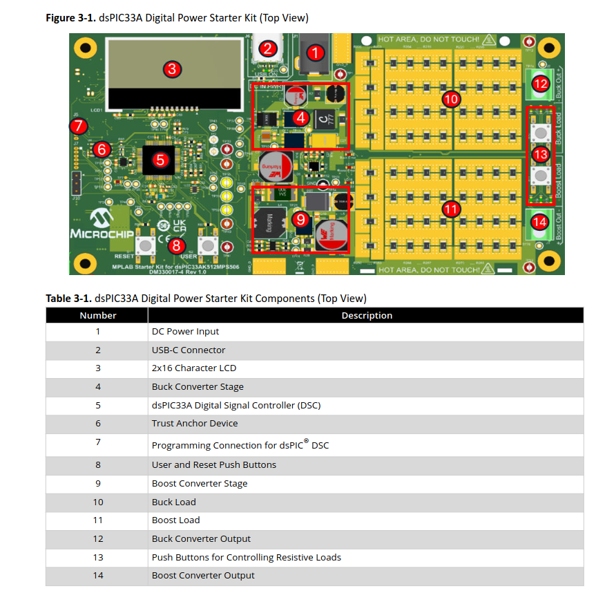
dsPIC33A Digital Power Starter Kit mit Komponentenliste
Figure 3-1. dsPIC33A Digital Power Starter Kit (Top View) 1 2 3 4 5 6 7 8 9 10 11 12 13 14 HOT AREA, DO NOT TOUCH! LCD1 Buck Converter Stage Buck Load Boost Load Buck Converter Output Push Buttons for Controlling Resistive Loads dsPIC33A Digital Signal Controller (DSC) Trust Anchor Device Programming Connection for dsPIC DSC User and Reset Push Buttons MPLAB Starter Kit for dsPIC33A912MPS506 DM30017-4 Rev 1.0 Table 3-1. dsPIC33A
in „Neue Bauteile: vom Radar bis zum Widerstand“ · Mikrocontroller und Digitale Elektronik · · Screenshots
-
PDF
irfiz34n.pdf
nC) DS G Fig 5. Typical Capacitance Vs. Fig 6. Typical Gate Charge Vs. Drain-to-Source Voltage Gate-to-Source Voltage 1000 1000 OPERATION IN THIS AREA LIMITED A BY R DS(on) t n r A u 100 t 100 C n a r 10µs
in „Mosfet Treiber Baustein“ · Analoge Elektronik und Schaltungstechnik ·
-
PDF
DS_SJEP120R100_rev2.1.pdf
Parameter Symbol Conditions Unit Min Typ Max Off Characteristics Drain-Source Blocking Voltage BV DS V GS= 0 V, ID= 600 µA 1200 - - V V = 1200 V, V = 0 V, Tj = 25 C - 100 600 DS GS o V DS = 1200 V, VGS = 0 V, Tj = 150 C - 300 - VDS = 1200 V, VGS < -15 V, Total Drain Leakage Current IDSS o - 1 - µA Tj
in „Siliziumkarbid-JFETS“ · Analoge Elektronik und Schaltungstechnik ·
-
PDF
DS2482-800-DS2482S-800.pdf
1 16 IO2 TYPICAL OPERATING CIRCUIT SCL 2 15 IO1 VCC SDA 3 14 IO0 RP Device #1 SDA Rt 1-Wire lines VDD 4 13 GND (I²C port) SCL IO1 IO2 Device #2 NC 5 12 IO4 µC IO3 AD0 IO5 AD2 6 11 IO5 AD1 IO6 AD2 IO7 AD1 7 10 IO6 DS2482 800 AD0 8 9 IO7 I C is a trademark of Philips
in „1-Wire Leitungs Problem“ · Mikrocontroller und Digitale Elektronik ·
-
PDF
1-buz171.pdf
d e f g h i l A V [V] GS D -14 k a -4.0 R DS (on)0.7 b -4.5 -12 c -5.0 0.6 d -5.5 j e -6.0 0.5 -10 f -6.5 g -7.0 i -8 h -7.5 0.4 h i -8.0 j -9.0 -6 g 0.3 k -10.0 f l -20.0 j -4 0.2 e d -2 0.1 VGS [V] = c a b c d e f g h i j b 5450-5.5 -6.0 -6.5 -7.0 -7-8.0 -9.0 -10.0 -20.0 0 a 0.0 0 -2 -4 -6 -8 -10 -12 -14 -16 V -19 0 -2 -4 -6 -8 -10 -12 A -16 V DS ID Typ. transfer characteristics I = f (V D GS ) Typ. forward transconductance g = f fs (ID) parameter: t = 80 µs parameter: t = 80 µs, p p V ≥ 2 x I x R V
in „IRF9Z34N als Ersatz für BUZ171“ · Analoge Elektronik und Schaltungstechnik ·
-
PDF
datasheet.pdf
) 2.0 2.6 4.0 Vdc DS GS D Threshold Temperature Coefficient (Negative) — 5.3 — mV/⋅C Static Drain–Source On–ResistancGS(V= 10 Vdc,DI = 15 Adc) RDS(on) — 0.067 0.08 Ohm Drain–Source On–Voltage V Vdc DS(on) (VGS = 10 Vdc,DI
in „verstärkerschaltung“ · Analoge Elektronik und Schaltungstechnik ·
-
PDF
I2C_Sheet.pdf
8 9 R82 B P4 10 JP1 9 *) R82/C32 are required to filter PWM noise for EMC reasons B P5 10 INT 10R 14 SCL P6 11 11 DB4 P4 C55 0u1 15 12 SDA n P7 12 DB5 P5 C57 C32 PC0 G 13 DB6 P6 0u1 100uF R74 14 DB7 P7 BL+ 15 LED-A 10K INTRTC 8 PWM1 SP7 16 LED-K 3 SP2W VCC U12 DS3232 GND 8x2 Q6 NXV75UP R77 JP19 4 Vcc
in „NXP PCA8574 hat Phänomen mit 2 Adressen“ · Mikrocontroller und Digitale Elektronik ·
-
PDF
HYCON-Tech-HY2213-BB3A_C113632.pdf
23-6 (Type 2)...................................................................................13 14. REVISION HISTORY ..............................................................................................................................14 © 2012-2015 HYCON Technology Corp DS-HY2213-V05_EN www.hycontek.com
in „LiFePo Balancer: CF-4S30A-A“ · Analoge Elektronik und Schaltungstechnik ·
-
PDF
P0603BDL.pdf
D(ON) V DS= 10V, V GS = 10V 160 A V = 4.5V, I = 35A Drain-Source On-State R GS D 7 15 mΩ Resistance 1 DS(ON) V GS= 10V, ID= 35A 4.2 6.8 Forward Transconductance 1 gfs VDS = 5V, D = 20A 80 S DYNAMIC Input Capacitance
in „Am3 Mainboard Vcore instabil wenn kalt“ · PC Hard- und Software ·
-
PDF
IRF4905.pdf
On-Resistance Vs.Temperature IRF4905PbF 7000 V = 0V, f = 1MHz 20 I = -38A CGS = C + C , C SHORTED D iss gs gd ds ) 6000 Crss = Cgd ( V DS = -44V Coss = Cds + Cgd e16 V = -28V ) a DS F 5000 o ( C iss V c e12 n 4000 r i C o a oss - p 3000 t C t 8 , a C 2000 G C rss ,S G4 1000 - FOR TEST CIRCUIT 0 A 0 SEE FIGURE 13
in „Frage zu Push Pull Abwärtswandler“ · Analoge Elektronik und Schaltungstechnik ·
-
PDF
device_list_hilo_all03_v9-12.pdf
*CAT28F002B *CAT28F002T CAT28F010/I CAT28F010V5/I CAT28F020/I CAT28F512/I CAT28F512V5/I <<DALLAS>> DS1213B (2K*8) DS1213B (8K*8) DS1213C (32K*8) DS1213C (8K*8) DS1213D (128K*8) DS1213D (32K*8) DS1213D (512K*8) DS1213D (8K*8) DS1216B (2K*8) DS1216B/C/E (8K*8) DS1216C/D/E (32K*8) DS1216D/F (128K*8) DS1216F (32K*8) DS1216F (8K*8) DS1220Y/AB/AD DS1225AB/AD/D/E/Y DS1230Y/AB DS1235Y/AB DS1243Y DS1244Y DS1245EE DS1245Y/AB DS1248Y DS1286 DS12887 DS1386 (32K*8) DS1386 (8K*8) DS1387 DS1486 DS1630Y/AB DS1642 DS1643 DS1645EE
in „PROM programmieren“ · Mikrocontroller und Digitale Elektronik ·
-
PDF
0900766b81417515.pdf
Temperature Fig. 6 On-Resistance Variation with Temperature DMG4511SK4 4 of 9 July 2011 Document number: DS32042 Rev. 4 - 2 www.diodes.com © Diodes Incorporated DMG4511SK4 3.0 20 V 2.7 18 ( E A 2.4 16 L ) O 2.1 (14 TA= 25°C V T L 1.8 E12 O R H R S 1.5 D = 250µA C10 R E H 1.2 C 8 T R T 0.9 U A S 6 , S H0.6
in „Datenblatt DMG4511SK4 COMPLEMENTARY PAIR MOSEFT“ · Analoge Elektronik und Schaltungstechnik ·
-
PDF
Funkmodul.pdf
-433-3V Transmitter 433MHz 3 Volt Operation +9dBm FM-RX2-418A-5V Receiver, 418MHz 5 Volt Operation 14kbps FM-RX2-418F-5V Receiver, 418MHz 5 Volt Operation. Fast Version 40kbps FM-RX2-433A-5V Receiver, 433MHz 5 Volt Operation 14kbps FM-RX2-433F-5V Receiver, 433MHz 5 Volt Operation. Fast Version 40kbps Receiver, 418MHz 3 Volt Operation 14kbps FM-RX2-418A-3V FM-RX2-418F-3V Receiver, 418MHz 3 Volt Operation. Fast Version 40kbps FM-RX2-433A-3V Receiver, 433MHz 3 Volt Operation 14kbps FM-RX2-433F-3V Receiver, 433MHz 3 Volt Operation. Fast
in „Funkübertragung über uC“ · Mikrocontroller und Digitale Elektronik ·
-
PDF
MCP73871-Data-Sheet-20002090E__2_.pdf
-Lead QFN (4 mm x 4 mm) temperature range of -40°C to +85°C. 2008-2019 Microchip Technology Inc. DS20002090E-page 1 MCP73871 Package Types MCP73871 20-Lead QFN* E N S T T U E B O I NI C V 20 19 18 17 16 OUT 1 15 VBAT VPCC 2 14 V EP BAT SEL 3 21 13 PROG1 PROG2 4 12 PROG3 THERM 5 11 VSS 6 7 8 9 10 S
in „Fehlersuche beim MCP73871“ · Mikrocontroller und Digitale Elektronik ·
-
PDF
PIC16F1503.pdf
PIC16(L)F1503 Data Sheet 14-Pin Flash, 8-Bit Microcontrollers 2011 Microchip TechPreliminary DS41607A Note the following details of the code protection feature on Microchip devices: • Microchip products meet the specification
in „Versorgungsspannung vom PIC mit PIC messen“ · Mikrocontroller und Digitale Elektronik ·
-
PDF
LM2937.pdf
Transient Response Ripple Rejection DS011280-13 DS011280-14 DS011280-15 Output Impedance Maximum Power Maximum Power Dissipation Dissipation (TO-220) (TO-263) (Note 2) DS011280-16 DS011280-17 DS011280-18 5 www.national.com 7 3 9 Typical Performance Characteristics (Continued) 2 M L Low Voltage Behavior Low Voltage Behavior Low Voltage Behavior DS011280-19 DS011280-20 DS011280-21 Output at Voltage Output at Voltage Extremes Output Capacitor ESR Extremes DS011280-24 DS011280-22 DS011280-23 Peak Output Current DS011280-25 Typical Application DS011280
in „Minimale Hardware zum Auto CAN-Bus abhören“ · Mikrocontroller und Digitale Elektronik ·
-
PDF
buz30a.pdf
Drain current I = (T ) P tot= (T )C D C parameter: V ≥ 10 V GS 130 22 W A 110 18 Ptot 100 D 16 90 14 80 12 70 60 10 50 8 40 6 30 4 20 2 10 0 0 0 20 40 60 80 100 120 ˚C 160 0 20 40 60 80 100 120 ˚C 160 T C TC Safe operating area Transient thermal impedance I = (V ) Z = (t ) D DS th JC p parameter: D
in „Elektronische Last mit 2 MOSFETs“ · Analoge Elektronik und Schaltungstechnik ·
-
PDF
dds_ds558.pdf
dB -100 -112 dB -120 -140 -0.5 -0.25 0 0.25 0.5 Frequency Figure 14: Taylor Series Corrected DDS – Frequency Sweep Simulation, 35 Tones 12 www.xilinx.com DS558 April 19, 2010 Product Specification LogiCORE IP DDS Compiler v4.0 Core Architecture Overview Figure 15 provides
-
PDF
542-01945-0-Z86E04.pdf
identify which of the E04/E08 product variants most closely match the us- er’s application requirements. DS97Z8X1104 P R E L I M I N A R Y 1 Z86E04/E08 CMOS Z8 OTP Microcontrollers Zilog FEATURES 14 Input/Output Lines Two Programmable 8-Bit Counter/Timers, Each with 6-Bit Programmable Prescaler Six Vectored
in „Pollin Ladegerät WCFD0801500IFOON : Rückwärts Ingenieur gesucht !“ · Mikrocontroller und Digitale Elektronik ·
-
PDF
A100_IRF3415_IF.pdf
DS D I DrainStoS±ource LeaOage Current BBB BBB 25 VDS= 150V, VGS = 0V DSS BBB BBB 250 "A V = 120V, V = 0V, T = 150°C DS GS J -ateStoS±ource Forward LeaOage BBB BBB 100 V GS= 20V GSS -ateStoS±ource keherse
in „Suche IR 513H“ · Analoge Elektronik und Schaltungstechnik ·
-
Datei
main.c
); lcd_puts("Einstellungen:"); cli(); } } void disptemp(int sensor) { // Routine für 2x40 LCD if ( DS18X20_start_meas( DS18X20_POWER_PARASITE, &gSensorIDs[sensor-1][0] ) == DS18X20_OK ) { delay_ms(DS18B20_TCONV_12BIT); if ( DS18X20_read_meas( &gSensorIDs[sensor-1][0], &subzero, &cel, &cel_frac_bits)
in „Interrupts machen mich irre... HILFEEEE!!! :-)“ · Mikrocontroller und Digitale Elektronik ·
-
PDF
BME680.pdf
Modifications reserved |Data subject not change without notice | Printed in Germanyumber: BST-BME680-DS001-00 Revision_1.0_072017 Bosch Sensortec | BME680 Datasheet 14 | 50 3. Sensor usage 3.1 Sensor modes The sensor supports low-level power modes: sleep and forced mode. These modes can be selected using
in „PIR-Sensor wird von BME680 gestört, warum?“ · Mikrocontroller und Digitale Elektronik ·
-
PDF
BME680.pdf
Modifications reserved |Data subject not change without notice | Printed in Germanyumber: BST-BME680-DS001-00 Revision_1.0_072017 Bosch Sensortec | BME680 Datasheet 14 | 50 3. Sensor usage 3.1 Sensor modes The sensor supports low-level power modes: sleep and forced mode. These modes can be selected using
in „BME680 Berechnung Temperatur Luftfeuchtigkeit Druck Gas Fragen Initialisierung Assembler ASM ATmega8“ · Mikrocontroller und Digitale Elektronik ·
-
PDF
DS1339.pdf
Capacitance (SDA, SCL) CI/O (Note 12) 10 pF Oscillator Stop Flag (OSF) Delay OSF (Note 13) 100 ms 4 of 18 2 DS1339 I C Serial Real-Time Clock POWER-UP/DOWN CHARACTERISTICS (T = -40▯C to +85°C) (Note 1, Figure 1) A PARAMETER SYMBOL CONDITIONS MIN TYP MAX UNITS Recovery at Power-Up t (Note 14) 2 ms REC V CC Fall
in „Sehr lange Zeitspannen?“ · Mikrocontroller und Digitale Elektronik ·
-
PDF
OV5620_CLCC_DS__1.3_.pdf
Inc. Version 1.3, February 15, 2007 O mni ision Timing Specifications Timing Specifications Figure 14 Serial Bus Timing Diagram t t t F HIGH R SCL t tSU:STO t LOW t HD:STA SU:DAT SDA(IN) tSU:STA AA tHD:DAT tBUF SDA(OUT) t DH 5620CLCC_DS_014 Table 7 Serial Bus Timing Specifications Symbol Parameter Min
-
PDF
ch32v003_getting_started.pdf
i2c_start 26 i2c_startaddr 26 i2c_stop 26 i2c_write_nack 26 i2c_write 27 i2c_write16 27 i2c_read 27 ds18b20_single.h / ds18b20_single.c 28 Der Header ds18b20_single.h 28 Die Funktionen von ds18b20_single 28 ds18b20_reset 28 ds18b20_gettemp 28 oled_i2c / oled_i2c_sw 29 Einstellung des Headers (nur für
in „CH32V003: Selbstbauprogrammer und "Getting started"“ · Projekte & Code ·
-
PDF
en.CD00002654.pdf
I = 1 mA, V = 0 100 V (BR)DSS Breakdown voltage D GS V DS= max rating 50 µA DSS Zero gate voltage V = max rating, Drain currentGSV= 0) T C=125°C 500 µA s ) GSS Gate-body leakage V GS= ± 20 V ±400 nA current DS = 0) u c VGS(th) Gate threshold voltage V DS= VGS
in „STE250NS10 Mosfet“ · Analoge Elektronik und Schaltungstechnik ·
-
PDF
22070a-53890.pdf
900 800 V (700 e 600 VR= 0.8V t 500 o V = 3.0V V400 R G300 R W200 P100 V = 5.0V R 0 0 2 4 6 8 10 12 14 16 18 20 PWRGD Sink Current (mA) FIGURE 2-31: Dynamic Load Response. FIGURE 2-33: Power Good Pulldown Voltage Vs Load. FIGURE 2-32: Dynamic Load Response. FIGURE 2-34: Startup Current. DS22070A-page
in „[V] 50St.LowNoise Microchip LDO MCP1824T 3,3V/300mA SOT223-5 mit Shutdown“ · Markt ·
-
PDF
FDC6327C.pdf
are • N-Channel 2.7A, 20V. R = 0.08Ω @ V = 4.5V produced using Fairchild Semiconductor's advanced DS(on) GS PowerTrench process that has been especially tailored RDS(on)= 0.12Ω @ V GS = 2.5V to minimize on-state resistance and yet maintain low gat• P-Channel -1.6A, -20V.DS(on) 0.17Ω @ V GS = -4.5V charge
in „Port-Stromverstärkung,Push-Pull-Treiber“ · Analoge Elektronik und Schaltungstechnik ·
-
PDF
OZ890-Datenblatt.pdf
=1024us The SC delay time = (N+1)*(SC delay unit), so its range is 8us~32.8ms CONFIDENTIAL OZ890 - DS-V1.6 Page 14 OZ890 Over-Voltage (OV) And Under-Voltage (UV) Protection Parameter Test Condition MIN TYP MAX Unit OV Detection Threshold 13bits programmable (0-5V) OV Release Value 13bits programmable
in „Schaltung für aktiven 3s Balancer gesucht“ · Analoge Elektronik und Schaltungstechnik ·
-
PDF
TF5000CI.pdf
ordering information. Pinout CD54HC164, CD54HCT164 (CERDIP) CD74HC164, CD74HCT164 (PDIP, SOIC) TOP VIEW DS1 1 14 VCC DS2 2 13 Q 7 Q 3 12 Q 0 6 Q1 4 11 Q5 Q2 5 10 Q 4 Q3 6 9 MR GND 7 8 CP CAUTION: These devices are sensitive to electrostatic discharge. Users should follow proper IC Handling Procedures. Copyrigh
in „CPU SAA7219 per Jtag auf Basis FT2232H ansprechen - Tool schreiben“ · PC Hard- und Software ·
-
PDF
DS18B20-PAR_TO-92__12_BIT_0_5__Fehler.pdf
? DS18B20-PAR TX SERIAL NUMBER Y Y Y 6 BYTES DS18B20-PAR TXBIT 1 DS18B20-PAR X MASTER TX DS18B20-PAR T BIT 1 CRC BYTE BIT 1 X MASTER T XIT 1 N N BIT 1 BIT 1 MATCH? MATCH? Y Y DS18B20-PAR X BIT 63 MASTER T
in „Genauigkeitsangabe auf einem Thermometer“ · Mechanik, Gehäuse, Werkzeug ·
-
PDF
DS_IRLZ44N-IR.pdf
, Source-to-Drain Voltage (V) V DS , Drain-to-Source Voltage (V) Fig 7. Typical Source-Drain Diode Fig 8. Maximum Safe Operating Area Forward Voltage IRLZ44NPbF 50 RD V DS VGS 40 D.U.T. ) R G ( +V n - DD e 30 u 5.0V C i Duty Factor ≤
in „IRLZ44N Logic Level? Welcher Parameter?“ · Mikrocontroller und Digitale Elektronik ·
-
PDF
IRLZ44N-IR_Reichelt.pdf
, Source-to-Drain Voltage (V) V DS , Drain-to-Source Voltage (V) Fig 7. Typical Source-Drain Diode Fig 8. Maximum Safe Operating Area Forward Voltage IRLZ44NPbF 50 RD V DS VGS 40 D.U.T. ) R G ( +V n - DD e 30 u 5.0V C i Duty Factor ≤
in „PWM-Drehzahlregelung Wasserpumpe mit DC bürstenloser Motor“ · Mikrocontroller und Digitale Elektronik ·