-
PDF
project.pdf
PB13 M1INB X X X Motor Drivers N 25 PA2 0 1 2 3 4 5 0 1 P PB12 51 M1INA T T T C36 G A S D A A A A C C B B B E E E E E E E E E B B C D A D 1uF P V V P P P P P P P P P P P P P P P P P P P P V V C33 100nF 6 7 8 9 0 1 2 3 4 5 6 7 8 9 0 1 2 3 4 5 6 7 8 9 0 STM32F407VGT6 +5V +5V P2 +5V P3 2 2
in „Schaltplan so richtig? STM32F407VG“ · Mikrocontroller und Digitale Elektronik ·
-
Datei
diskio.c
in period / of 1 ms to generate card control timing. */ void disk_timerproc (void) { WORD n; BYTE s; n = Timer1; /* 1kHz decrement timer stopped at 0 */ if (n) Timer1 = --n; n = Timer2; if (n) Timer2 = --n; s = Stat; if (MMC_WP) /* Write protected */ s |= STA_PROTECT; else /* Write enabled */ s &= ~STA_PROTECT; if (MMC_CD) /* Card is in socket */ s &= ~STA_NODISK; else /* Socket empty */ s |= (STA_NODISK | STA_NOINIT); Stat = s; }
in „STM32 <-> AVR“ · Mikrocontroller und Digitale Elektronik ·
-
 Bild
Bild
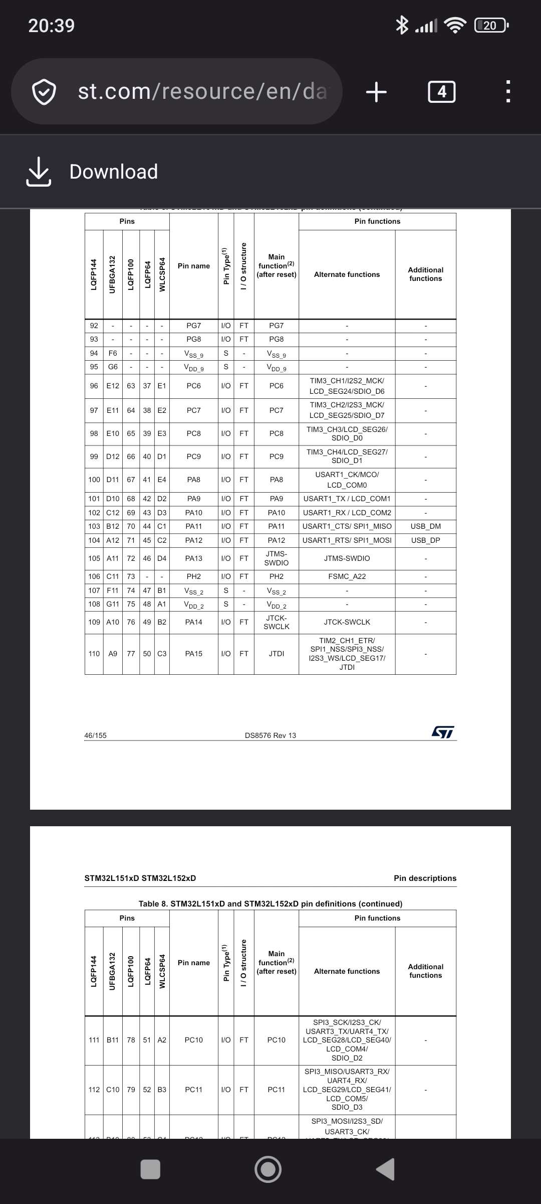
Pinbelegungs-Tabelle eines STM32L151x/STM32L152xD Mikrocontrollers
reset) Alternate functions Additional functions LQFP144 UFBGA132 LQFP100 WLCSP48 92 PG7 I/O FT PG7 93 S Vss_9 94 F6 S Vss_9 95 GR Vss_9 96 E12 63 37 E1 I/O FT PC7 97 E11 64 38 PA8 I/O FT PC8 98 E10 65 39 E3 I/O FT PC9 99 D12 66 40 D1 I/O FT PC9 100 D11 67 41 E4 PA8 I/O FT PC9 101 D10 68 42 D2 I/O FT PC10
in „SWD-Zugriff funktioniert nur über ProgrammerSocket“ · Mikrocontroller und Digitale Elektronik · · Screenshots
-
Datei
mmc_stm32f1.c
SPI_I2S_FLAG_RXNE) == SET)); d = SPI_I2S_ReceiveData(SPI1); buff[1] = d; buff[0] = d >> 8; /* Store it */ SPI_8Bit(); SetLED(GELB,DISABLE); } #if FF_FS_READONLY == 0 /* Send multiple byte */ static void xmit_spi_multi
in „STM32F103 Bluepill mit 128kb lässt sich nicht flashen“ · Mikrocontroller und Digitale Elektronik ·
-
PDF
stm32_magic_eye2.pdf
14 J3 PC7 PB7 MD1 N N AudioJack4_Ground 39 PC8 PB8 61 12 FMT G G 0 k H10 H11 H12 H13 H14 H15 H16 H17 40 PC9 PB9 62 D A 1 1 8 µ S 51 29 MD1 5 2 R C 1 1 0 R2 PC10 PB10 1n 1n GNDA 1 R1 D73 D74 D75 D76 D77 D78 D79 D80 GNDD GNDA 52 PC11 PB11 30 MD0 R
in „STM32F103 und I2S Probleme“ · Mikrocontroller und Digitale Elektronik ·
-
PDF
Schematic_ED2109-015.pdf
DIO0 h 100k DIO0 i 6 VDD FB 4 2 3 13 VCC N 1 GND X1 5 SGND PGND 1 +3.3V R18 8 GND ANT 9 1 ANT R16 100k 1 10 GND 2 GND GND LM2623MM/NOPB GND 100k IC1A 3 GND 10 18 R22 RFSolutions RFM95W-868S2 P1 +3.3V RST 11 PA0-WKUP PB0 19 NP TE Connectivity 1909763-1 GND 1 TX2 12 PA1 PB1 20 GND
-
Datei
ADC_dual_103.c
); /* USER CODE BEGIN 2 */ while (HAL_ADCEx_Calibration_Start(&hadc1) != HAL_OK) ; sprintf(temp, "%s\r\n", "Hello! Sunt STM32!"); HAL_UART_Transmit(&huart1, (uint8_t *)temp, (uint16_t)strlen(temp), HAL_MAX_DELAY); /* USER CODE END 2 */ /* Infinite loop */ /* USER CODE BEGIN WHILE */ while (1) { /* USER
in „STM32F1xx: Injected simultanous ADC läuft nicht“ · Mikrocontroller und Digitale Elektronik ·
-
 Bild
Bild
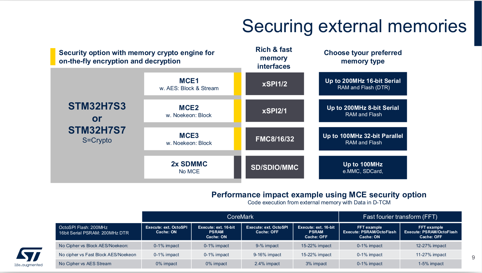
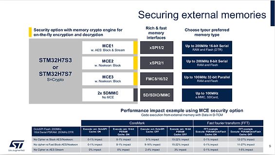
Präsentation von STM32H7S/S Speicherverschlüsselungsoptionen
external memories Security option with memory crypto engine for on-the-fly encryption and decryption STM32H7S3 or STM32H7S7 S=Crypto MCE1 w. AES: Block & Stream xSPI1/2 Up to 200MHz 16-bit Serial RAM and Flash MCE2 w. Noekeon: Block xSPI2/1 Up to 200MHz 8-bit Serial RAM and Flash MCE3 w. Noekeon: Block FMC8/16/32 Up to 100MHz 32-bit Parallel RAM and Flash 2x SDMMC No MCE SD/SDIO/MMC Up to 100MHz e.MMC, SDCard Performance impact example using MCE security option Code execution from external memory with Data
in „Neue STM32H7-Variante, Eclipse-Daten zur IoT-Adoption und neue Kameras“ · Mikrocontroller und Digitale Elektronik · · Screenshots
-
PDF
extended_serial_library.pdf
nicht erreicht war *cptr : Zeiger auf den auszugebenden AsciiZ-String Beispiel: ansi.vertikalout(14,8, 0x4e, 30, " Hallo Welt "); Ausgabe: ein vertikal angezeigter "Hallo Welt"-Text mit gelber Schriftfarbe auf rotem Grund. txtleftout void txtleftout(int xorg, int yorg, char *s); Mit txtleftout ist es
in „Arduino und struct gefallen sich nicht !“ · Mikrocontroller und Digitale Elektronik ·
-
Datei
SPI_Setup.c
) ); //wait until transmit complete SPI_I2S_SendData(SPI3, 0x04); //address PA0 while( !(SPI3->SR & SPI_I2S_FLAG_TXE) ); //wait until transmit complete SPI_I2S_SendData(SPI3, 0x01); //address BA0 while( !(SPI3->SR & SPI_I2S_FLAG_TXE) ); //wait
in „STM32F4: Flash Speicher Zugriff über SPI“ · Mikrocontroller und Digitale Elektronik ·
-
PDF
refclock.pdf
D1 STM32L412 N3 +3.3V +3.3V +3.3V MCP1754ST-33 12 VBUS 1 YE VBUS IN OUT 1 VDD 11 W4 17 2 13 USB-A GND 4 1 5 1 5 VDD 5 C7 8 k C11 C3 C5 C10 VDDA X D3 R 3 D4 D2 D3 74HC86 DSR 6 2u2 8 100n 2 100n 7 100n 100n
-
Datei
irmpconfig.h
300 bytes #define IRMP_SUPPORT_PENTAX_PROTOCOL 1 // Pentax >= 10000 ~150 bytes #define IRMP_SUPPORT_S100_PROTOCOL 0 // S100 >= 10000 ~250 bytes #define IRMP_SUPPORT_ACP24_PROTOCOL 0 // ACP24 >= 10000 ~250 bytes #define IRMP_SUPPORT_RADIO1_PROTOCOL 0 // RADIO, e.g. TEVION >= 10000 ~250 bytes (experimental
in „Umfrage: welche IR-Protokolle nutzt ihr mit IRMP?“ · PC Hard- und Software ·
-
Datei
SK6812.cpp
addressable RGB LED, becuase it relies on a division multiple of the 72Mhz clock frequence on the STM32 SPI to generate the correct width T0H pulse, of 400ns +/- 150nS SPI DIV32 gives a pulse width of 444nS which is well within spec for the SK6812 but is probably too long for the WS2812 which needs
in „STM32 Bluepill -> SK6812 (auf Basis von WS2812B Lib)“ · Projekte & Code ·
-
Datei
startup_stm32f20x.S
/** ****************************************************************************** * @file startup_stm32f2xx.s * @author MCD Application Team * @version V1.0.0 * @date 18-April-2011 * @brief STM32F2xx Devices vector table for Atollic TrueSTUDIO toolchain. * This module performs: * - Set the initial SP
in „STM32 FreeRTOS Projekt (Makefile - GCC)“ · Projekte & Code ·
-
PDF
emw3165.pdf
Flash_SPI1_NSS 6 PB3 I/O FT Flash_SPI1_SCK 7 PB4 I/O FT Flash_SPI1_MISO TIM2_CH3,TIM5_CH3,TIM9_CH1, 8 PA2 I/O FT I2S2_CKIN,USART2_TX, ADC1_2 TIM2_CH2,TIM5_CH2,SPI4_MOSI/I2S4_SD, 9 PA1 I/O FT USART2_RTS, ADC1_1 10 VBAT S - - 11 - - - Not connected TIM2_CH4,TIM5_CH4,TIM9_CH2, 12 PA3 I/O FT I2S2_MCK,USART2
in „EMW3165 - Der ESP8266 Killer ?“ · Mikrocontroller und Digitale Elektronik ·
-
Datei
STM32F4_lcd.c
1000); t2 = SysTick->VAL - 140; while(SysTick->VAL > t2); } // Routinen zur Ausgabe auf LCD 2x16 uint8_t lcd_status(void) // oberstes Bit ist busy-flag, Rest: Adresse { uint8_t temp = 0; GPIO_InitTypeDef GPIO_InitStructure; GPIO_InitStructure.GPIO_Pin = GPIO_Pin_12 | GPIO_Pin_13 | GPIO_Pin_14 | GPIO_Pin
in „LCD-Modul 2x16 am STM32F4Discovery-Board“ · Projekte & Code ·
-
Datei
startup_stm32f4xx.S
/** ****************************************************************************** * @file startup_stm32f4xx.s * @author MCD Application Team * @version V1.0.0 * @date 30-September-2011 * @brief STM32F4xx Devices vector table for Atollic TrueSTUDIO toolchain. * This module performs: * - Set the initial
in „STM32F4 C++ springt bei __libc_init_array in den HardFault“ · Mikrocontroller und Digitale Elektronik ·
-
Datei
startup_stm32f4xx.S
/** ****************************************************************************** * @file startup_stm32f4xx.s * @author MCD Application Team * @version V1.0.2 * @date 05-March-2012 * @brief STM32F4xx Devices vector table for Atollic TrueSTUDIO toolchain. * This module performs: * - Set the initial SP
in „FreeRTOS IDLE-Task“ · Mikrocontroller und Digitale Elektronik ·
-
PDF
schaltplan.pdf
0.47uF 1 2 GND 1 2 6 2 GND 3 1 2 4 SWDIO GND 6 1 _ N N _ 4 I 5 3 4 6 C3 C4 4 I I I I I 0 J GND 7 5 6 8 SWCLK 0 _ GND GND 9 7 8 VREG_5 4.7uF 1uF 9 J GND - GND 9 9 10 10 TRACESWO LDL1117S50R - GND 2 2 M GND NRST 1 GND VIN 3 V12 M 2 VOUT_1 VOUT_2 4 V5 HB_ST M20-9980545 N$8 IS_2 2 1 U2A IS_1 N$9 2 1 IS_1 PA0 STM32F4X5RG U2B 4 4 3 3 IS_2 STM32F4X5RG V33 6 6 5 5 IN_M_2 8 8 7 7 14 PA0/WKUP PC0 8 10 10 9 9 15 PA1 PC1 9 18 VSS_2 VDD_2 19 GND IN_M_1 IN_M_2 16 10 63 32 V33 17 PA2 PC2 11 INH_M VSS VDD_3 48 INH_EXT
-
Datei
triple_interleaved.c
configured, this is done through SystemInit() function which is called from startup files (startup_stm32f40xx.s/startup_stm32f427x.s) before to branch to application main. To reconfigure the default setting of SystemInit() function, refer to system_stm32f4xx.c file */ /* ADC configuration */ ADC_Config
in „STM32, triple mode Interleaved mode, periodisch falsch“ · Mikrocontroller und Digitale Elektronik ·
-
PDF
STM32H7-Base.pdf
/TRACESWO) PE3 3 45 PH3 JTAG_T ST PIU 10162 PB4(NJTRST) PE4 P IU 1 0 3 PI U1 04 5 PH4 GND 163 4 46 S0 +3V3 PIU 10163 PB5 PE5 P IU 1 0 4 PI U1 04 6 PH5 R5R PIU110164 P IU 1 0 5 PI U1808 3 P I X1 0 1 JTAGX_VTGT0VT GT PIR50 PIR502 PB6 PE6 PH6 PIU110165 PI6U1 06 8 PI U1808 4 P I X1 0 2 22R COR 1 +3V3 167
in „STM32H7 und JTAG: Irgendwelche Fallstricke“ · Mikrocontroller und Digitale Elektronik ·
-
PDF
MC_productmatrix_022005.pdf
8-bit Family h x / t l l a r r i e e e R y / t s n c a i s o o i d k n T ( t u n o v B U t P P d g h g l t O m B e I t / ) p I 2 i o ) a b M - a i e . r e / e r ( L - o e B r e a N M . P B d n e n c W
in „8051-Derivat mit zwei UART gesucht“ · Mikrocontroller und Digitale Elektronik ·
-
Datei
stm32f4_discovery_lcd.c
, 0x00, 0x00, 0x00, 0x60, 0x92, 0x0c, 0x00, 0x00, 0xff, 0xff, 0xff, 0xff, 0xff, 0xff, 0xff, 0xff}; sFONT Font16x24 = { ASCII16x24_Table, 16, /* Width */ 24, /* Height */ }; sFONT Font12x12 = { ASCII12x12_Table, 12, /* Width */ 12, /* Height */ }; sFONT Font8x12 = { ASCII8x12_Table, 8, /* Width */ 12, /* Height */ }; sFONT Font8x8 = { ASCII8x8_Table, 8, /* Width */ 8, /* Height */ }; /** @defgroup stm32f4_discovery_LCD * @brief This file includes the LCD driver for (LCDSSD2119) * @{ */ /** @defgroup stm32f4_discovery_LCD_Private_TypesDef
in „STM32F4Discovery mit CooCox CoOS-RTOS und printf“ · Projekte & Code ·
-
PDF
STM32F4-BASE_BRD.pdf
1 SV1 10 10 SV5 1 1 4VS 01 1 1 1 N 6 R R8 O SV6 J R9 C JP7 JP15 2 X2 2 MCU1 C20 C18 2 4 3 1 C C 1 R10 3 3 0 C22 C U1 2 U2 R11 J S 1 C 1 J C1 S JP11 1 1 1 1 1 D1 1 3 4 2 C C C C C JP5 3 4 C2X1 4 1 7 1 9 P 4 R R R C R R2 C6 C J J X 2 3 L 8 C93
in „STM32F407 (100pin) Basisboard - Review bitte“ · Mikrocontroller und Digitale Elektronik ·
-
Datei
usb.c
/* ST STM32F103C8T6: USB als COM Port betreiben */ #include "StdTypes.h" #include "STM32F103all.h" #include "usb.h" /* die Transfer-Puffer für zeichenweises In und Out über den USB */ #define txLen 256 char UsbTxBuf
in „USB CDC von Stefan Frings und WS“ · Mikrocontroller und Digitale Elektronik ·
-
Datei
irsndconfig.h
bytes #define IRSND_SUPPORT_PENTAX_PROTOCOL 0 // Pentax >= 10000 ~150 bytes #define IRSND_SUPPORT_S100_PROTOCOL 0 // S100 >= 10000 ~150 bytes #define IRSND_SUPPORT_ACP24_PROTOCOL 0 // ACP24 >= 10000 ~150 bytes /*---------------------------------------------------------------------------------------
in „Umfrage: welche IR-Protokolle nutzt ihr mit IRMP?“ · PC Hard- und Software ·
-
Datei
main.c
) { int i = 0; while (TxIdx < BufferSize) { /* Wait for SPI_MASTER Tx buffer empty */ while (SPI_I2S_GetFlagStatus(SPI_MASTER, SPI_I2S_FLAG_TXE) == RESET); /* Send SPI_MASTER data */ SPI_I2S_SendData(SPI_MASTER, SPI_MASTER_Buffer[TxIdx++]); Delay(0xAFFFF); for (i=0; i<= TxIdx; i++) { /* Turn on led
in „STM32 SPI2 als Master sendet nichts“ · Mikrocontroller und Digitale Elektronik ·
-
 Bild
Bild
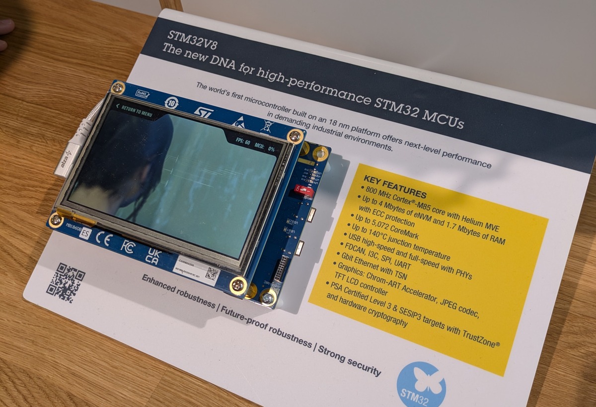
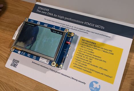
STM32V8 Mikrocontroller Display auf Informationsblatt
STM32V8 The new DNA for high-performance STM32 MCUs The world's first microcontroller built on an 18 nm platform offers next-level performance in demanding industrial environments KEY FEATURES 800 MHz Cortex-M85
in „EmbeddedWorld 2026, Tag 1 – AI fressen Elektronik auf“ · Mikrocontroller und Digitale Elektronik · · Fotos
-
Datei
startup_stm32f30x.S
/** ****************************************************************************** * @file startup_stm32f30x.s * @author MCD Application Team * @version V1.0.0 * @date 04-Spetember-2012 * @brief STM32F30x Devices vector table for RIDE7 toolchain. * This module performs: * - Set the initial SP * - Set
in „STM32 Takt Frage“ · Mikrocontroller und Digitale Elektronik ·
-
Datei
stm32f10x_it.c
SysTick_Handler(void) { } /******************************************************************************/ /* STM32F10x Peripherals Interrupt Handlers */ /* Add here the Interrupt Handler for the used peripheral(s) (I2C), for the */ /* available peripheral interrupt handler's name please refer to the startup */ /* file (startup_stm32f10x_xx.s). */ /******************************************************************************/ /** * @brief This function handles I2C1 Event interrupt request. * @param None * @retval : None */ void
in „stm32 Cortex I2C : Master zieht SCL auf Masse“ · Mikrocontroller und Digitale Elektronik ·
-
Datei
stm32f10x_it.c
SysTick_Handler(void) { } /******************************************************************************/ /* STM32F10x Peripherals Interrupt Handlers */ /* Add here the Interrupt Handler for the used peripheral(s) (I2C), for the */ /* available peripheral interrupt handler's name please refer to the startup */ /* file (startup_stm32f10x_xx.s). */ /******************************************************************************/ /** * @brief This function handles I2C1 Event interrupt request. * @param None * @retval : None */ void
in „Cortex I2C zu kurze Impulsdauer“ · Mikrocontroller und Digitale Elektronik ·
-
Datei
startup_stm32f4xx.c
/** ****************************************************************************** * @file startup_stm32f4xx.s * @author Coocox * @version V1.0 * @date 03/05/2012 * @brief STM32F4xx Devices vector table for RIDE7 toolchain. * This module performs: * - Set the initial SP * - Set the initial PC == Reset_Handler
in „GCC STM32F4 -> Wie Variablen auf RAM bereiche verteilen“ · Mikrocontroller und Digitale Elektronik ·
-
Datei
startup_stm32f4xx.c
/** ****************************************************************************** * @file startup_stm32f4xx.s * @author Coocox * @version V1.0 * @date 03/05/2012 * @brief STM32F4xx Devices vector table for RIDE7 toolchain. * This module performs: * - Set the initial SP * - Set the initial PC == Reset_Handler
in „STM32 ohne CMSIS aber mit den includes etc. in CoIDE“ · Mikrocontroller und Digitale Elektronik ·
-
PDF
TC1797_UM_v1.1.pdf
. 8-5 [1] User´s Manual I-8 V1.1, 2009-05 TC1797 Table of Contents 8.4 Address Map of the FPI Bus System . . . . . . . . . . . . . . . . . . . . . . . . . . 8-7 [1] 8.4.1 Segments 0 to 14 . . . . . . . .
in „TC1797 - keine Datenblätter?“ · Mikrocontroller und Digitale Elektronik ·
-
Datei
mbportserial.c
/* * MODBUS Library: ARM STM32 Port (FWLIB 2.0x) * Copyright (c) Christian Walter <cwalter@embedded-solutions.at> * All rights reserved. * * ARM STM32 Port by Niels Andersen, Elcanic A/S <niels.andersen.elcanic@gmail.com> * * $
in „FreeRTOS + LWIP + UART Interrupt Problem“ · Mikrocontroller und Digitale Elektronik ·
-
Datei
gfx_pictures.h
vornimmt (5 Bit fuer rot, 6 Bit fuer gruen, 5 Bit fuer blau) Verfuegbare Formate sind: PCX 256 Farben BMP s/w, 4, 16, 256 Farben MCU : AVR / STM32 / STM8 25.01.2019 R. Seelig ------------------------------------------------------ */ #ifndef in_gfxpictures #define in_gfxpictures // Fuer Verwendung mit einer
-
Datei
inpucapproblem.c
- mw_alt ); // u16Last = u16Temp; return(mw); } //........................................... uint8_t zaehlen(void) // wenn STM-Ausgang bei high erwischt { int16_t mw=0; DDRD &= 191; // ICR=PORTD6 wird Eingang if (PIND & 64) // ist PORTD6 high? (Abfrage funktioniert!) { mw++; }; return (mw); } //..
in „input capture funktioniert nicht - Verständnisfrage“ · Mikrocontroller und Digitale Elektronik ·
-
Datei
06072010.txt
) function which is called from startup file (startup_stm32f10x_xx.s) before to branch to application main. To reconfigure the default setting of SystemInit() function, refer to system_stm32f10x.c file */ USART2Init(); // char highBits1; // char lowBits1;
in „STM32 Interrupts“ · Mikrocontroller und Digitale Elektronik ·
-
 Bild
Bild
Startseite der ST Community Webseite
to increase your skills. Search all content... 161,029 Topics 563,763 Replies 107,420 Members What's happening now See the latest activity, browse open questions, and explore categories. Recent activity No best answer Categories xpress_embedo Associate III · Asked in STM32CubeIDE (MCUs) No ST-LINK detected! Please connect ST-LINK and restart the debug session. 0 8 1 21 minutes ago DeryaVar Visitor · Asked in STM32 MCUs Products STM 32 Nucleo. F7 and H7 Connections 0 26 2 25 minutes ago Maxime_MARCHETTO ST Employee · Posted in Compliance and regulations Navigate
in „AI-VNA, 6GHz-Oszilloskop von Rigol, NEC-Frontend uvam“ · Mikrocontroller und Digitale Elektronik · · Screenshots

-
Datei
sysf103_init.c
zugehoerigen Header sind mittels defines die GPIO - Pins als Input / Output konfigurierbar. Hardware : STM32F103C8 IDE : keine (Editor / make) Library : libopencm3 Toolchain : arm-none-eabi 28.09.2016 R. seelig ------------------------------------------------------------- */ #include "sysf103_init.h" volatile
in „Einstieg Mikrocontroller Atmel“ · Mikrocontroller und Digitale Elektronik ·
-
Datei
stm32f10x_can.c
&= (u8)0x0000000F; CAN->sTxMailBox[TransmitMailbox].TDTR &= (u32)0xFFFFFFF0; CAN->sTxMailBox[TransmitMailbox].TDTR |= TxMessage->DLC; /* Set up the data field */ CAN->sTxMailBox[TransmitMailbox].TDLR = (((u32
in „STM32F10x Cortex M3 CAN Konfiguration“ · Mikrocontroller und Digitale Elektronik ·
-
PDF
STM32F4-BASEbrd.pdf
1 SV1 10 V 10 SV5 1 1 4VS 2 01 1 1 0 1 6 R R8 N F SV6 M J C 7 4 X2 5 CU R9 JP7 JP15 C C 1 0 C20 C18 R10 3 e 2 4 3 1 C U1 1 U2 P A S 1 C22 C R11 J P C1 1 t J 4 6 5 7 9 D1 S c JP11 61R C C C C C 1 3 n 4 2 71R C23X1 JP5 w o 3 4 4 w 3 4 5 C C R 02R R2 1 P J X W R R R D R 81R 1 C6 C C J C26 s o 1 1 6 91R L 87 C93 R15 s D D Di C R R C . E E Em D 72C R1 C2 e L L L S 1 SV2 20 1 SV3 10 01.03.2012 18:44:54 C:\Users\SuperK\13-Eagle\1-Projekte\STM32F407Vx_Baseboard\STM32F4-BASE.brd
in „STM32F407 (100pin) Basisboard - Review bitte“ · Mikrocontroller und Digitale Elektronik ·
-
Datei
startup_stm32l562ceux.s
/** ****************************************************************************** * @file startup_stm32l562xx.s * @author MCD Application Team * @brief STM32L562xx devices vector table GCC toolchain. * This module performs: * - Set the initial SP * - Set the initial PC == Reset_Handler, * - Set the
in „STM32 startet im HardFault“ · Mikrocontroller und Digitale Elektronik ·
-
Datei
ili9341.c
---------------------------------------- private defines -- #define __ILI9341_TOUCH_NORM_SAMPLES__ 8U // ----------------------------------------------------------- private macros -- #define __IS_SPI_SLAVE(s) (((s) > issNONE) && ((s) < issCOUNT)) #define __SLAVE_SELECT(d, s) \ if (__IS_SPI_SLAVE(s))
in „STM32U575 und ILI9341 SPI DMA Problem“ · Mikrocontroller und Digitale Elektronik ·
-
Datei
stm32F43x.lib.txt
EESchema-LIBRARY Version 2.2 Date: 08/04/16-12:40:10 # # stm32F43x # DEF stm32F43x U 0 40 Y Y 1 0 N F0 "U" 0 -100 50 H V C C F1 "stm32F43x" 0 100 50 H V C C F2 "MODULE" 0 0 50 H I C C F3 "DOCUMENTATION" 0 0 50 H I C C DRAW S -1900 1900 1900 -1900 1 0 0 N X BOOT0
-
PDF
panasonic_tx-p50u20b_e_tx-pr50u20_chassis_gpf13de_sm.pdf
16k M M AV-SW HK digital FE T T 32k S S TEMP SENSOR R2A11014FT Brazil FE MM3285ANRE FE DVB-T2 FE SLV-ADR 0x90 CXD2817R A TUNER E STM PDP-PANEL TO 4/19 TO 6/19 TO 13/19 TO 17/19 TO 2/19 TO 11/19 TO 5/19 TO 3/19 F 1 2 3 4 5 6 7 8 9 47 13.6
in „Panasonic TX-P50U20E“ · Analoge Elektronik und Schaltungstechnik ·
-
Datei
usart_nrf3.h
InformAlarmDataNO; typedef union { struct { //dong 20200520 u16 WCode; u8 Alarm_Id[6] ; u8 WNum[2]; u8 WTime1[4]; u8 WTime2[4]; u8 Data1[2]; u8 Data2[2]; } Data; u8 DataMsg[22]; } AlarmDataType; typedef struct { u8 Alarm_Id[6] ; //dong 20200520 u16 WCode; u8 WNum[2]; u8 WTime1
in „Wechselrichter Hoymiles HM-xxxx 2,4 GhZ Nordic Protokoll?“ · Mikrocontroller und Digitale Elektronik ·
-
Datei
main.c
configured, this is done through SystemInit() function which is called from startup file (startup_stm32f10x_xx.s) before to branch to application main. To reconfigure the default setting of SystemInit() function, refer to system_stm32f10x.c file */ /* System clocks configuration --------------------
in „STM32F103: Auswahl des richtigen ADC Modus“ · Mikrocontroller und Digitale Elektronik ·
-
PDF
spwf01.pdf
from 25 °C to peak temperature 8 minutes max. Figure 2. Soldering profile AM17477v1 8/16 DocID025635 Rev 2 SPWF01SA, SPWF01SC Regulatory compliance 7 Regulatory compliance RF compliance The RF certifications obtained are described in
in „Wlan2Serial Modul für 5 euro“ · Mikrocontroller und Digitale Elektronik ·
-
PDF
TMS470.pdf
any base modification (and resolve the cause of the abort) before restarting the instruction. 4.11.8 Instruction cycle times Normal LDM instructions take nS + 1N + 1I and LDM PC takes (n+1)S + 2N + 1I incremental cycles, where S, N, and I are as defined in Section 6.2, Cycle Types, on page 6-3. STM instructions
in „Vergleiche mit (2^n)-1 und -(2^n) schneller?“ · Mikrocontroller und Digitale Elektronik ·