Pin-out Diagram Figure 1-1. AT86RF230 Pin-Out Diagram S S S D D S 2 1 S S S D D S A A A A A A E A X X T 32 31 30 29 28 27 26 25 AVSS 1 24 IRQ Exposed Paddle AVSS 2 AVSS 23 SEL AVSS 3 22 MOSI RFP 4 21 DVSS AT86RF230 RFN 5 20 MISO AVSS 6 19 SCLK TST 7 18 DVSS RST 8 17 CLKM 9 10 11 12 13 14 15 16 S S R S D D
long) == 8. Note the absence of a 4-byte, 32-bit type. The patch proposes to change sozeof(long long) to be 4 bytes (32 bits). When and if the patch is included in gcc, we will need to change avr-libc accordingly. 7.14 Deprecated List Global eeprom
Break For On-chip Debug Only None N/A Note: 1. These instructions are only available in ATmega168. 14 2545RS–AVR–07/09 ATmega48/88/168 6. Ordering Information 6.1 ATmega48 Speed (MHz) Power Supply Ordering Code Package (1) Operational Range ATmega48V-10AI 32A ATmega48V-10MI 32M1-A ATmega48V-10PI 28P3
/50))= 32,2 nH, der Tabellenwert ist 27nH. Im RF12 wird ein um zwei Bauteile (im Bild C2 und L1 genannt) erweitertes Netzwerk empfohlen, das macht man um eine breitbandigere Anpassung zu erreichen. Betriebsspannung
von Bezugsquellen. csd-electronics IT-WNS Pollin Electronic RS Components Robotikhardware.de Links. AVR RFM12 RFM12 Protokoll Stack RF_SOAP RN-MikroFunk, kleines kompaktes AVR-Evaluationsboard für RFM12b und RFM12 Pollin_Funk-AVR-Evaluationsboard Sehr kleines/stromsparendes Funk-AVR-Evaluationsboard RN-MikroFunk
input. One 16-bit output operand and one 16-bit result input. Figure 3 shows the structure of the 32 general purpose working registers in the CPU. Figure 3. AVR CPU General Purpose Working Registers 7 0 Addr. R0 0x00 R1 0x01 R2 0x02 … R13 0x0D General R14 0x0E Purpose R15 0x0F Working R16 0x10 Registers
result input One 16-bit output operand and one 16-bit result input Figure 3 shows the structure of the 32 general purpose working registers in the CPU. Figure 3. AVR CPU General Purpose Working Registers 7 0 Addr. R0 0x00 R1 0x01 R2 0x02 … R13 0x0D General R14 0x0E Purpose R15 0x0F Working R16 0x10 Registers
40 / t 38 a a C 36 34 32 0 1 2 3 4 5 6 7 8 9 10 11 12 13 14 15 16 Processor number Abbildung 5.60: Selbsttest: Nullwert der Kapazitätsmessung 80 REF_R_KORR 60 V m 40 / o c 20 r c 0 e t o -20 V -40 -60 0 1 2 3 4 5 6 7 8 9 10
input. One 16-bit output operand and one 16-bit result input. Figure 3 shows the structure of the 32 general purpose working registers in the CPU. Figure 3. AVR CPU General Purpose Working Registers 7 0 Addr. R0 0x00 R1 0x01 R2 0x02 … R13 0x0D General R14 0x0E Purpose R15 0x0F Working R16 0x10 Registers
meiner 789-Schnittstelle messe ich 8-9 ca. 24 V (scheint ok), 7-9 hat ca. 5.5 V, wenn geheizt wird ca. 14 V. Folgendes dabei finde ich seltsam: * die 5.5 V im Ruhezustand liegen an der Therme an, auch wenn der Raumthermostat nicht angeschlossen ist. * die 14 V 7-9 scheinen unabhängig von der Solltemperatur
40 / t 38 a a C 36 34 32 0 1 2 3 4 5 6 7 8 9 10 11 12 13 14 15 16 Processor number Abbildung 5.60: Selbsttest: Nullwert der Kapazitätsmessung 80 REF_R_KORR 60 V m 40 / o c 20 r c 0 e t o -20 V -40 -60 0 1 2 3 4 5 6 7 8 9 10
input. One 16-bit output operand and one 16-bit result input. Figure 3 shows the structure of the 32 general purpose working registers in the CPU. Figure 3. AVR CPU General Purpose Working Registers 7 0 Addr. R0 0x00 R1 0x01 R2 0x02 … R13 0x0D General R14 0x0E Purpose R15 0x0F Working R16 0x10 Registers
voll und meine Werkzeugakkus halten nun wesentlich länger. Also bei mir geht das ganze auch mit den 14,4V Akkus tadellos! mfg Fasti
es gibt spezielle Hochtemperaturzellen z.b. von Sanyo mit C/10 dürfen diese 14-16 Stunden geladen werden und mit C/30 über 48 Stunden(wieviel drüber sagen Sie im Datenblatt aber auch nicht)
Verzeichnis gespeichert. Das Verzeichnis ist bei einer Standardinstallation am PC auf C:\Programme\Atmel\AVR Tools\AvrAssembler\Appnotes\. Einige Include-Dateien heißen AT90s2313: 2313def.inc ATmega8: m8def.inc ATmega16: m16def.inc ATmega32: m32def.inc ATTiny12: tn12def.inc ATTiny2313: tn2313def.inc Um sicher
auch, meine ich jedenfalls, auf der ST Seite eine Empfehlung zu C++ gelesen), würde ich mir das STM32F4 DISCOVERY STM32F407VGT6 STM32 ARM Cortex-M4 Development Board kaufen und damit anfangen. Da brauchst du zunächst keine Widerstände und auch nichts anderes kaufen. Die F0 und F1 Boards sind noch günstiger
-b.examiner.com/sites/default/files/styles/image_content_width/hash/e8/30/Williams_5a.jpg?itok=pI8cDdUW :-D Grüße Andreas
result input One 16-bit output operand and one 16-bit result input Figure 6 shows the structure of the 32 general purpose working registers in the CPU. Figure 6. AVR CPU General Purpose Working Registers 7 0 Addr. R0 0x00 R1 0x01 R2 0x02 … R13 0x0D General R14 0x0E Purpose R15 0x0F Working R16 0x10 Registers
AVR16/32DD14/20
MVIO - Multi-Voltage I/O
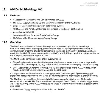
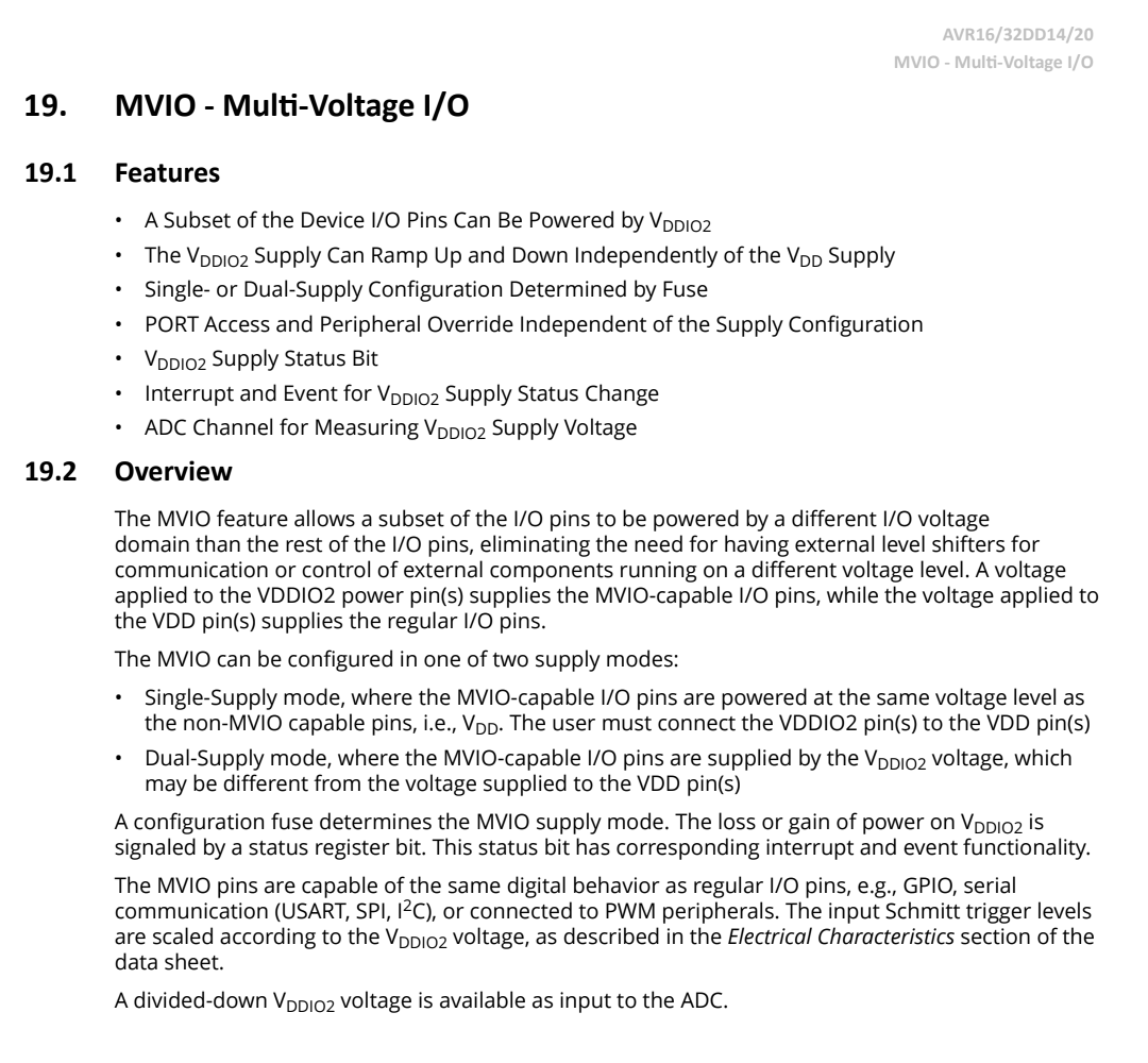
19. MVIO - Multi-Voltage I/O
19.1 Features
• A Subset of the Device I/O Pins Can Be Powered by VDDIO2
• The VDDIO2 Supply Can Ramp Up and Down Independently of the
2 Address 3 Array ref 0x0 Element 0 Element 1 Element 2 Element 3 - 0x4 Length - 0x8 Array header 14 AVR32 32049A–AVR32–09/06 AVR32 2.5 Trapping instruction 2.5.1 Entering traps Unimplemented instructions are automatically trapped. A trap is executed very much like the call instruction. Each unimplemented
deaktivieren damit die Walzen beim Abkühlen weiterlaufen. 12V Ralais schaltet die Heizung... Kosten 14,- der Rest kam aus der Bastelkiste :D
sobald der da war und ausprobiert wurde , grummel wurde gleiche ein synchronmotor mit 2,5 umdrehungen 14w (derzeit 12umdr. 14w) bestellt, die dinger mit 14w , gleiche Bauform gibts seit kurzem bei ebay :-) gruß Klaus
Debug Only None N/A Note: 1. These instructions are only available in ATmega168PA and ATmega328P. 14 8271BS–AVR–04/10 ATmega48A/48PA/88A/88PA/168A/168PA/328/328P 6. Ordering Information 6.1 ATmega48A (2) (1) Speed (MHz) Power Supply Ordering Code Package Operational Range ATmega48A-AU (5) 32A ATmega48A-AUR
sichert, und zwar auch nur die wirklich verwendeten Teile. Die Handhabung ist etwas komplexer als bei dd, eine gute Anleitung und ein ausführlicherer Vergleich der beiden Tools ist auf bitblokes.de zu finden. Unter Windows gibt es das Tool Win32DiskImager welches komplette bitweise Images (von SD-Karten
die Aufzeichnung starten: ./RasPi_logGPIO.sh [Liste mit GPIO-Pins] > ausgabedatei.txt Für die Pins 14, 31 und 23 sieht das Kommando z.B. so aus: ./RasPi_logGPIO.sh 14 31 23 > ausgabedatei.txt Die Aufzeichnung kann mit Strg+C gestoppt werden. Jetzt kann man die entstandene Datei (z.B. hier ausgabedatei.txt
input One 16-bit output operand and one 16-bit result input Figure 7-2 shows the structure of the 32 general purpose working registers in the CPU. Figure 7-2. AVR CPU General Purpose Working Registers 7 0 Addr. R0 0x00 R1 0x01 R2 0x02 … R13 0x0D General R14 0x0E Purpose R15 0x0F Working R16 0x10 Registers
migration to the left reduces the pin count and therefore also the available features. Figure 1-1. tinyAVR 1-Series Overview Flash 32KB 16KB ATtiny1614 ATtiny1616 ATtiny1617 8KB ATtiny814 ATtiny816 ATtiny817 4KB ATtiny417 2KB Pins 8 14 20 24 32 Devices with different Flash memory size typically also have
migration to the left reduces the pin count and therefore also the available features. Figure 1-1. tinyAVR 1-Series Overview Flash 32KB 16KB ATtiny1614 ATtiny1616 ATtiny1617 8KB ATtiny814 ATtiny816 ATtiny817 4KB ATtiny417 2KB Pins 8 14 20 24 32 Devices with different Flash memory size typically also have
38 a a C 36 34 32 0 1 2 3 4 5 6 7 8 9 10 11 12 13 14 15 16 Processor number Figure 5.51: Selftest: zero o▯set of the capacity measurement 80 REF C KORR 60 REF R KORR m / 40 o c 20 e o 0 e a o -20 V -40 -60 0 1 2 3 4 5
Programme und Spiele) existiert bereits und kann einfach vom PC auf die SD-Karte kopiert werden (FAT32) - das ist ein Lerncomputer: Verbindung über TTL-Serial-RSR232-USB-Adapter (FTDI-Kabel o.ä.) mit dem PC ist recht kompliziert für Anfänger
nicht blockierende Eingaben. Standard Microtronic kann nur blockierendes KIN: https://youtu.be/5fJnDdA0HZY https://hackaday.io/project/180252-a-retro-authentic-microtronic-emulator/log/199133-retrochallenge-retrochallenge-update-4

 Bild
Bild
 Bild
Bild