preamble" followed by a series of "data bits". So far, all of the "shot" signals I have tested use the same preamble; 3mS Carrier On / 6mS Carrier Off / 3mS carrier On (3/6/3). Each of the shot signals also contain 7 data bits which are used a little differently depending on the type of game. MegaTags
/EN 60950. To find the location of the serial ports onthe MOPS/386A board, please see the Appendix E: Connector Layout chapter. 8.2 Configuration You can set the two serial input/output interfaces to base I/O-address 3F8h, 2F8h, 3E8h, 2E8h, AUTO or disabled. You can set their interrupts to IRQ3 or IRQ4
). E96 E48 E24 E12 E6 E96 E48 E24 E12 E6 Values Values (±1%) (±2%) (±5%) (±10%) (±20%) (±1%) (±2%) (±5%) (±10%) (±20%) 1,00 X X X X X 3,30 X X X 1,02 X 3,32 X X 1,05 X X 3,40 X 1,07 X 3,48 X X 1,10 X X X
J6) 19 Data Sheet Rev1.1 V A R - 6 U L C U S T O M B O A R D D A T A S H E E T R E V 1 . 1 2.3.9.3 GPIO Connector (J8) Pin# VAR-6ULCustomBoard Signal Type Description 1 GPIO1_5 IO GPIO1[5] 2 NAND_CLE IO NANDCLE(usedbyonSoMNAND) 3 GPIO1_8 IO GPIO1[8] 4 NAND_WP_B IO NANDWriteProtect
flow angle ö min ) can also be adjusted Series resistance 1 can be calculated as follows: by using R 8(see figure 4). V – V R1max+ 0.85 x M Smax When the potential on Pin 2 reaches the set point level of 2 x Itot Pin 3, a trigger pulse is generated whose pulse width, t p whereas is determined from the
Pulse Voltage output monitoring 1 Load current Level Soft Reference detector shift start voltage 2 3 4 5 6 7 8 Figure 1. Block diagram TELEFUNKEN Semiconductors 1 (12) Rev.A1, 28-May-96 U2010B F e A B C C m o 2 M S1 7 1 N 9 6 G 9 F e A a B – C x e 7 m 1 l a m u a m n g 8 C 1 S u o a A s I e l D V S
global dynamic noprefixroute valid_lft 86394sec preferred_lft 86394sec inet6 fe80::e5d:b3f4:8bc7:6ad7/64 scope link noprefixroute valid_lft forever preferred_lft forever $ ip r default via 192.168.1.1 dev wlp112s0 proto dhcp metric 600 169.254.0.0/16 dev virbr0 scope link
MOC3053M TYPICAL CHARACTERISTICS 1.7 400 ) V A ( 1.6 ( 300 E T A 1.5 E 200 T R O 1.4 R 100 V U D C R 1.3 T 0 A TA= −40°C A W 1.2 S −100 O TA= 25°C − F 1.1 O −200 − T = 85°C − F A M V 1.0 IT −300 0.9 −400 1 10 100 −3 −2 −1 0 1 2 3 IF− LED FORWARD CURRENT (mA) VTM
Hier mal ein Beispiel, wie sowas in der Praxis aussieht: https://docs.oracle.com/en/servers/x86/x8-8/service-manual/img/bios_main_security_settings_secure_boot_key_management.jpg Bauform B. schrieb im Beitrag #7632404: > Der nächste Zug von Microsoft könnte > sein, dass Windows nur noch
Windows auch keine Ausnahme, aber echte Hardware, die heute ja auch fast immer Software enthält, wird m.E. nie unter echten Bedingungen getestet, geschweige denn wirklich benutzt. Anders ist mir das nicht erklärbar. Beispiel: Aldi-E-Zahnbürste. 8 Programme, schickes buntes Display mit lustigen Symbolen
ADVANTAGES CONFIGURATIONS APPLICATIONS Ultra-low and compact package profile Buck DC-DC converters (5.3mm height x 24.8mm length x 32.3mm width) Boost Battery chargers Surface mountable via standard reflow process Full-bridge Switching and resonant power supplies (Available in Tape & Reel packaging) Half-bridge
the hole at a rapid retract rate. The drill then moves to point B, and the cycle is repeated. The same sequence is followed for holes C, D and E. After the completion of the last hole the drilling head may be instructed to return to the original starting point or to another parking position and automatically
buffered) DB14 P2.6 (buffered) DB15 P2.7 (buffered) /CS P0.22 RS P0.23 /WR P0.24 /RD P0.25 RESET RESET 2.8.3 Display Interface The CN7 Databus interface of the Land Tiger LPC17XX development board can be connected to a 2.8 or 3.2 inch 320X240 TFT color LCD. The datalines are connected to P2.0 ... P2.7 and
MANUAL RESET D C T D - R X P M O R D D C D D D E 3 T I N V R CAN0 P CAN1 P O D N 0 C VDD1V8 D R U I I N V A B S P C I U D U S M N J14 VDDPLL A X E SYSTEM CONTROLLER B 1 PIO A PIO B I 8 XOUT - 3 AT91SAM7A3-LQFP100 A 2 I H P z P
selbst aus der Nase ziehen: Eine weiße LED wird mit 17mA betrieben und hat eine Flussspannung von 3,3V. (5V-3,3V)/100R=17mA 8x17mA=136mA Gesamtstromaufnahme Pro LED wird also jeweils ein 100R Widerstand vorgeschaltet. Unwichtig schrieb im Beitrag #7626009: > Die 8x LED´s hätte man in Reihe
schrieb im Beitrag #7626021: > Eine weiße LED wird mit 17mA betrieben und hat eine Flussspannung von 3,3V. > (5V-3,3V)/100R=17mA > 8x17mA=136mA Gesamtstromaufnahme > Pro LED wird also jeweils ein 100R Widerstand vorgeschaltet. Genau so. > Das 5V Netzteil lag bestimmt sowieso schon in der >
multiplexers and switches may exceed this capacitance because they connect multiple paths together. s 1 4 e l r 0 4 g m 2 7 s a 0 f e u 6 e a 4 4 . l xxxxxxxxxxxxxxxxxxxxx xxxxxxxxxxxxxxxxxxxxxxxxxx xxxxxxx x x x xxxxxxxxxxxxxxxxxxxxxxxxxxxxxx xxxxxxxxxxxxxxxxxxx xx xx xxxxx xxxxxxxxxxxxxxxxxxxxxxxxxxx xxxxxxxxxxxxxxxxxxx
1 0 eul G 0 e U l T e ng U n i A G D edi St cat no C xa M mm51. 0=t mm2. 0=t mm360. 0x8x51 l epa Tevo me R reziral oP B8131# M3 v r e p ur r a e i t S 6 u C 5 2-R0.4± 0.05 0 SS V ) 3 H MDC V 3 1 " FE RI 0 7 D ± 6
y a T B D 3 ii m 0 1 p m e ± ± (2.4) 9± 0.2 e s n i r n r n P0.62x(14-1)=8.06± 0.05 t t t u o s l . W=0.32± 0.03 a 0.1± 0.03 O n R T e gn 0 30- n n U r m A 2 ?025±0 o U e D H A S 0S T 1 2 C G V S R V FE C C . . V41 S V V C C a ± ± 1 2 d o 0 . . 2-? 0.8± 6.2± 0.1 0 S p r ± 6 6 0.05 ± c p t . 2 t r n 1 o m i 1.874 x C t S (2.01) 0.3 e a u a M C T m u 5 1 v 5 l o . G e m e 0 a m R t T 60 v 0 c 3 . 0 t x 0 1 r 9 ( e P S ) l i ) n S er ) ) P ap r / A/ 2
Hallo in die Runde, ich habe mir früher mal bei eBay einen guten gebrauchten Weller-WSP-80-Lötkolben relativ günstig ersteigert und schaue noch immer ab und an mal nach guten Angeboten. Dabei fallen ja die Angebote chinesischer Händler auf, z.B. https
Standard in allen Fertigungen waren? > aber bei THT-Handbestückung im Akkord muss man auch da auf > 8er-Lötspitzen (800 °F, d.h. 425 °C) zurückgreifen. In unser damaligen Fertigung hat niemand 8er-Spitzen verwendet! Aber nach Magnastat kam WECP, fast gleich aufgebauter Kolben mit Elektronikregelung
µc.net Henrik Haftmann TU Chemnitz. Text -> Lautschrift -> Phoneme -> PCM-Wave AVR-Freaks-Diskussion SAM Software Automatic Mouth C64-Programm konvertiert nach C Mehr Sinn macht das Abspielen von kurzen Tonfetzen (Samples), die man kreativ zusammenfügt (fünf-zehn Uhr drei-ßig). 8 kHz x 8 Bit = 8.000 Byte
GitHub 🎧 Hörproben auf Thorsten-Voice.de 🐸Coqui.ai 🎧 Hörproben Englisch Mozilla-Forum Mycroft Mimic 3. Performantes offline TTS welches auch auf Raspberry Pi 3/4 gut nutzbare Geschwindigkeiten bietet (100+ Sprachen unterstützt). Thorsten-Voice ist als deutsche Stimme auch mit dabei. Die alte Anleitung
SG-C17xxZ27S 7 R Sele,tSon Guide TJ VZ m m Z 2 7 RPart Number IF(AV)(Max.) Min. Max. e V o V BatteZy 2 SG-C17LXZ27R 35 A Stator R 1 7 V SG-C17VLZ27R 50 A o t - C SG-C177xZ27R SG-C17VVZ27S 60 A 235 °C 24 V 30 V N S G C 1 SG-C17WVZ27S 80 A G - SG-C17WVZ27R S SG-C17xxZ27-DSE Rev.1.3 SANKEN
Beides zusammen geht nicht. "The ESP32 only supports either Bluetooth or WIFI, but not both at the same time. So if you use A2DP, you will not be able to use any functionality which depends on WIFI (e.g. FreeRTOS queues)" Quelle: https://github.com/pschatzmann/ESP32-A2DP/wiki/WIFI-and-A2DP-Coexistence
anstelle des Akkus. Funktioniert. Beim weiteren Rumtesten habe ich festgestellt, dass ich vom ESP32S3 DevKit v4 am 5V Pin nur 4.8V bekomme, wenn ich das DevKit per USB mit einer Stromquellen wie Ladegerät oder Laptop versorge. Vielleicht hat jemand eine Idee, warum das so ist...? Ich habe dann mit
Hallo, ganz so wie gedacht funktioniert es bei mir doch noch nicht crontab -e: [code] 0 */3 * * * cd speedtest && sh speedtest.sh [code] (zwischen */3 und cd speedtest soll 3x*) es soll alle 3 Stunden in den Ordner speedtest gewechselt werden und das skript speedtest.sh ausgeführt
Server immer in der Vollen Stunde und Halben Stunde überlastet sind. Habe meinen cron-Befehl dann auf 8 Minuten nach (alle 3 Stunden) gändert. [code] 8 */3 * * * sh /home/speedtest/speedtest.sh >> /home/cron.log 2>&1 [/code] Werde ich dann morgen sehen, ob es das Problem war. Aber zumindest weiß
Yalu X. schrieb im Beitrag #7610304: > Michael B. schrieb: >> Yalu X. schrieb: >>> Logisch. Ein E-Auto hat im Vergleich zu einem V-Auto weniger Teile, >>> die bei Ausfall zu einer Panne führen. Da die Starterbatterie
are not read in a sequen- tially manner from the lookup table but just every second value. At the same sample frequency an output signal with twice the frequency is generated (see Figure 4). Figure 4. Doubling the Output Frequency (X SW = 2) V 1/fl 2 3 4 5 6 7 8 9 10 11 12 t T/2 T In using not every
eine Anfrage zum Upload. Doku ist China typisch in Dropbox: https://www.dropbox.com/sh/epucei8lmoz7xpp/AAAmon04b1DiSOeh1q4nAhzAa?e=1&spm=a2g0o.detail.1000023.1.676claGNlaGNb1&dl=0 https://www.dropbox.com/sh/pznvlzx8qx5nfr3/AABpzhSyjqH0qWNYgMvxqAA9a?e=1&spm=a2g0s.imconversation.0.0.109b3e5fckU9p0&
Gesamtlänge jetzt auch, es kommmen 18432 Byte, entspricht 192 * 192/2, [c] // image data 4 Bit -> 8 Bit for(int y=0; y < 192; y++) { for(int x=0; x < 192/2; x++) { uint8_t val1 = (imageBuffer[x + y*96] >> 4) * 16; uint8_t val2 = (imageBuffer[x + y*96] & 0xf) * 16; lineBuffer
Debugwire, UPDI und ISP). Die Ausnahme ist HV-Programmierung. MPLAB Snap kann auch für ARMe der SAM-Reihe von Atmel/Microchip und für PICs und dsPICs genutzt werden, das aber nicht alles mit dem Microchip Studio, sondern mit MPLAB X. Letzlich ist MPLAB Snap eine etwas abgespeckte Variante des PICKit
software-tools/programmers-and-debuggers/avr-updi-high-voltage/ https://onlinedocs.microchip.com/oxy/GUID-8D61C0B9-A97F-4F4D-99F8-1D7424264C2A-en-US-1/GUID-E5FA70C8-E80C-471B-A036-574F30027BDD.html Das kann MPLAB Snap nicht.
transmitted in a CANopen network in the form of messages. These messages basically consist of a COB-ID and 8 data bytes. COB-ID The 11-bit COB-ID is made up as follows: 10 9 8 7 6 5 4 3 2 1 0 Function code Node number X X X X X X X X X X X X free, to be selected The COB-ID only determines the message object
Name Description Version PSMN3R7-100BSE D2PAK plastic, single-ended surface-mounted package (D2PAK); 3 SOT404 terminals (one lead cropped); 2.54 mm pitch; 11 mm x 10 mm x 4.3 mm body 7. Limiting values Table 4. Limiting values In
= 0.5V(2) 8 20 — mA I Low Level Output Current OL OL VCC= 2.3V to 5.5V; V = 0.7V(2) 10 24 — mA OL IOH= -8mA; VCC = 2.3V [3] 1.8 — — V IOH= -10mA; VCC = 2.3V [3] 1.7 — — V [3] IOH= -8mA; VCC = 3.0V 2.6 — — V VOH
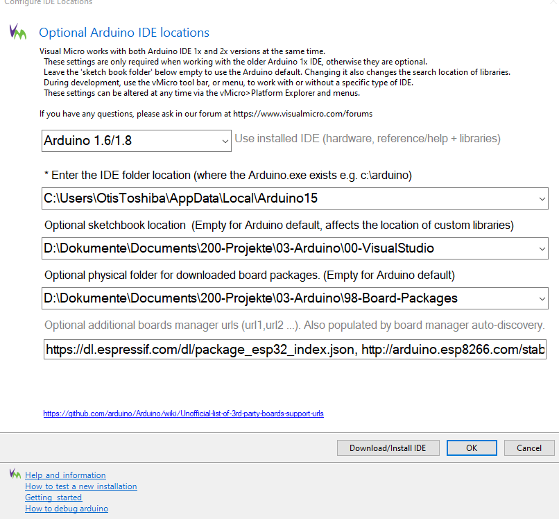
Optional Arduino IDE locations
Visual Micro works with both Arduino IDE 1x and 2x versions at the same time.
These settings are only required when working with the older Arduino 1x, otherwise they are optional.
Leave the sketch book folder below empty to use the Arduino default
, e.g., disable Find My to steal an iPhone or use Express Cards and Keys 3.2.3 Low-Power Mode Setup. When the iPhone shuts down due to steal money or physical assets. There is a usability aspect, for to
s 2.0 s t t 25˚C e –30˚C e u 1.5 u 2.0 C C –30˚C l 1.0 l p p u u 1.0 S 0.5 S 0.0 0.0 0 1 2 3 4 5 6 7 8 9 10 0 1 2 3 4 5 6 7 8 9 10 Input Voltage V(V) Input Voltage V(V) R 5VL45C 3.0 Topt=80˚C 2.5 A ( s 2.0 25˚C t e –30˚C u 1.5 C l 1.0 p u S 0.5 0.0 0 1 2 3 4 5 6 7 8 9 10 Input Voltage VV) 2 Detector Threshold vs. Temperature R 5VL27C R 5VL36C 3.0 4.0 V V E 2.9 E 3.9 D +V DET D d d o 2.8 o 3.8 s s +V DET r r T 2.7 T 3.7 r –V DET r c c t 2.6 t 3.6 –V DET
VSS=0V) : Parameter Symbol Range Unit Power supply voltage VDD -0.5~+5.5 V Logic input voltage V -0.3~VDD+0.3 V IN Working temperature Topt -20~+80 ℃ Storage temperature Tstg -50~+120 ℃ ESD pressure V ESD 4K V 8. The electrical parameters (unless otherwise specified, TA=-20 ~ +70 ℃, VDD=4.5 ~ 5.5V, VSS
V 62 V G 0G 65 2 V1C CV 8 CC V 52 75 42 7R 85 7 R T DN G 32 6R 95 6 R B 2 X 22 5R 06 5 R KL C1 X 12 H r 4R 16 4 R 3OI M PS 02 M N e 3R 26 3 R 2OI M PS 91 1 p G i 2R 36 2 R OSI M M PS 81 C 1 r 1 R 3 O CC V Y d 1R 46 71 D D 0R
given for a constant DC supply double make DB-DM or sinusoidal AC supply. Other operating conditions (e.g. pulse control, contact ramp voltage, half wave rectifying, etc.) may lead to characteristics other than specified. Triple make Form 3 contact Coil-contact circuit data Insulation parameters between
die Sache nicht gegessen. Es ist ja nicht jeder Lebensmittelchemiker und vertüddelt sein Leben auf E-Nummern Partys.
Immer strebend bemüht habe ich jetzt die Version 2.3.0 installiert. Diese arbeitet erfreulicherweise deutlich schneller und kennt bei pinMode jetzt auch INPUT_PULLDOWN. Die "Raspberry Pi RP2040 Boards (3.7.0)" werde ich auch noch dazupacken. Sehr erfreulich
1.2 mm max height SCALE 2.000 SMALL OUTLINE PACKAGE C 6.6 TYP A 6.2 PIN 1 INDEX 0.1 C SEATING AREA 36X 0.5 PLANE 38 1 2X 9.8 9.6 9 NOTE 3 19 20 0.27 38X B 4.5 0.17 4.3 0.08 C A B SEE DETAIL A (0.15) TYP 2X 0.95 MAX NOTE 5 19 20 2X 0.95 MAX NOTE 5 0.25 GAGE PLANE 1.2 MAX 4.70 39 3.94 THERMAL PAD 0.75 0.15
°C/W R θJA Junction-to-Ambient ––– 110 2 www.irf.com IRLR6225PbF 1000 1000 VGS VGS TOP 10V TOP 10V 3.5V 3.5V A 3.0V A 3.0V t 2.3V t 2.3V e 2.0V e 2.0V r 1.8V r100 1.8V C BOTTOM 1.5V C BOTTOM 1.5V e e r 100 r o o - - - - 1.5V i i 10 r r , , I I 1.5V ≤60µs PULSE WIDTH ≤60µs PULSE WIDTH Tj = 25°C Tj =
AUGUST 2001 − REVISED JANUARY 2007 APPLICATION INFORMATION 5 F + C 1 2 0 R 1 D 1 F L 2 1u 1 C .0 C D 8 V G Z 3 R B 3 2 F P C 1 0 1 u C 1 F + 3 2 C 2 0 6 u 2 u + 2 7 C 2 8 7 6 5 C 4 F c T D E c U N R V O G F 1 u H F C 7 8 7 6 5 L 7 8 p 4 x . C 0 T R O R U C 1 5 4 4 O I T O 8 R 7 4 3 B H B L C U 2 U 0 S
reader or is FFh. Length (Data Length Indicator) Denotes the length of the Data block. Software Guide 1.3 125kHz OEM.odt Page 8 of47 Kronegger GmbH 125kHz OEM Data This part contains the command and data. The command values are the same as in ASCII protocol mode like ’s’ for select or 'x' for reset, whereas

 Bild
Bild