-
PDF
MIK-k05-AVR_uc.pdf
zu seinem Höchstwert TOP und anschließend wieder zurück auf $0000 zäNlt. Bei einer programmierten PWM-Auflösung von N Bit errechnet sich TOP zu TOP = 2 – 1; Die Frequenz f PWM, mit der sich die PWM-Zyklen wiederholen, errechnet sich zu f = f / (2+1- 2), PWM T/C1 wobei f T/C1ie über die Bits CS10 ... CS12 in Register TCCR1B gewählte Eingangsfrequenz von T/C1 und N die über die Bits PWM10 und PWM11 in Register TCCR1A gewählte PWM-Auflösung ist. Tab. 4.3.3 zeigt diese Zusammenhänge. Wenn der Zählerstand in TCNT1 mit dem Wert der 10 niederwertigsten Bits in OCR1A bzw. OCRIB übereinstimmt
in „Warum komme ich beim Auswärten des ADC's nur bis 25% ?“ · Mikrocontroller und Digitale Elektronik ·
-
Datei
rgb.asm
.include "m8def.inc" .def akku = r16 .def akku2 = r17 .def pwm1 = r18 .def pwm20 = r19 .def pwm3 = r20 .def pwmcount = r21 .def status = r22 .def verzug = r23 .org 0x000 rjmp start .org INT0addr ; External Interrupt0 Vector Address reti .org INT1addr ; External
in „Programm geht nicht mehr“ · Mikrocontroller und Digitale Elektronik ·
-
Datei
ausgangspositionmitte.ino
5; servonum<6; servonum++) pwm.setPWM(5,0,370); delay(3000); for (int servonum = 4; servonum<5; servonum++) pwm.setPWM(4,0,357); delay(2000); for (int servonum = 3; servonum<4; servonum++) pwm.setPWM(3,0,365); delay(2000); for (int servonum = 2; servonum<3; servonum++) pwm.setPWM(2,0,370); delay(3000); for (int servonum = 1; servonum<2; servonum++) pwm.setPWM(1,0,650); delay(3000); for (int servonum = 0; servonum<1; servonum++) pwm.setPWM(0, 0, 490); } }
in „Roboterarm mit Gestensteuerung HILFE I2C“ · Mikrocontroller und Digitale Elektronik ·
-
Datei
Inout.c
group A pins */ /* bit 15 0: 0=IOPB7, 1=TCLKINA bit 14 0: 0=IOPB6, 1=TDIRA bit 13 0: 0=IOPB5, 1=T2PWM/T2CMP bit 12 0: 0=IOPB4, 1=T1PWM/T1CMP bit 11 0: 0=IOPB3, 1=PWM6 bit 10 0: 0=IOPB2, 1=PWM5 bit 9 0: 0=IOPB1, 1=PWM4 bit 8 0: 0=IOPB0, 1=PWM3 bit 7 0: 0=IOPA7, 1=PWM2 bit 6 1: 0=IOPA6, 1=PWM1 bit 5 0
in „TMS320LF2407 ???“ · Digitale Signalverarbeitung / DSP / Machine Learning ·
-
Datei
main.c
16 (); void Wipper2 (void); // // ++++ Main-Programm ++++ // int main(void) { DDRD |= (1<<PWM_0); // Ausgang PWM als Hellichkeit-Dimmer DDRB |= (1<<PWM_1); // Ausgang PWM als Farben-Dimmer //PORTD |= (1<<PWM_0); //PORTB |= (1<<PWM_1); DDRD &= ~(1<<wip1_auf); // Eingänge Wipper 1 DDRD &= ~(1<
in „PWM steuert Helligkeit & Farbe bei LED-Module“ · Projekte & Code ·
-
 Bild
Bild
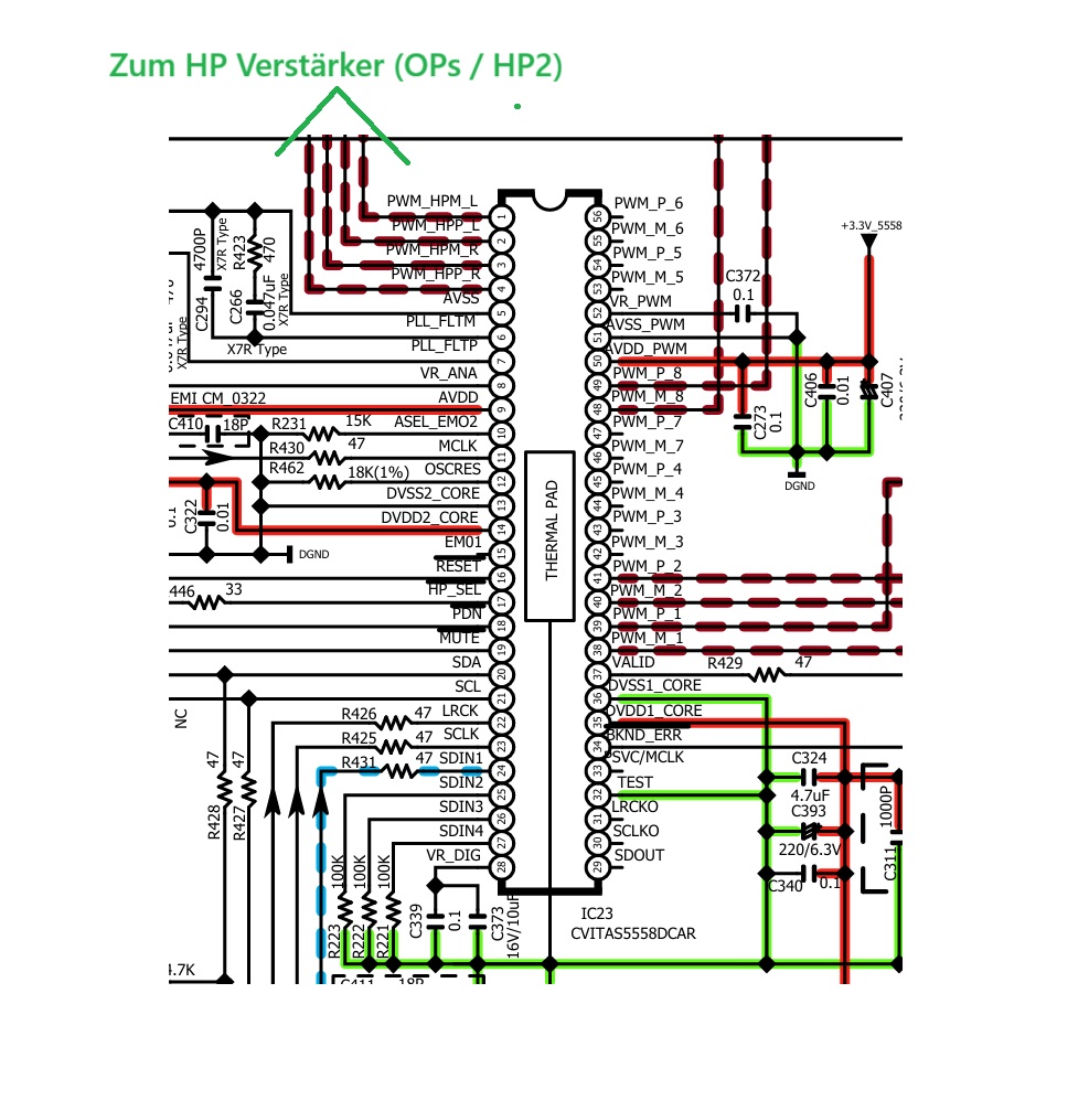
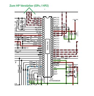
Schaltplan eines Verstärkers
Zum HP Verstärker (OPs / HP2) PWM_HPM_L PWM_HPM_C PWM_HPM_R PWM_HPP X7R C294 470pF C266 0.1uF X7R AVDD MCLK OSCRES AVDD DVSS2_CORE DVDD2_CORE RESET HP_SEL PDN MUTE SDA SCL LRCK SCLK SDIN1 SDIN2 SDIN3 SDIN4 VR_DIG SDOUT VR_PWM AVSS PLL_FLTM VR_ANA PWM_P_6 PWM_M_6 PWM_P_5 PWM_M_5 PWM_P_4 PWM_M_4 PWM_P_3 PWM_M_3 PWM_P_2 PWM_M_2 PWM_P_1 PWM_M_1 DVSS1_CORE DVSS2_CORE DVSS_CORE +3.3V_5558 C372 0.1 C406 0.01 C407 THERMAL PAD R429 47 R426 47 R425 47 R431
in „Hifi Kompaktanlage mit Bluetooth Sender ausstatten“ · Analoge Elektronik und Schaltungstechnik · · Schaltpläne
-
Datei
dualMotorPll.c
ecSpinUpFaulhaber1226(&motor.current,&motor.target,DDS_TUNE_1HZ,DDS_F_SAMPLE); fc200Dbg(false); } void fc200Pwm1Init(void) { // the hardware PWM: PCONP |= 1<<PCONP_PWM1; // ports P2.0..P2.6 as PWMs: pin function 1 for (int p=P2_0; p<=P2_5; ++p) pinFunction(p,1); PWM1.tcr = 1<<PWMTCR_RESET; PWM1.pr = PCLK_PWM1 /F_SWITCH /PWM_A -1; PWM1.mr0 = PWM_A; PWM1.mcr = 1<<PWMMCR_MR0_RESET | 1<<PWMMCR_MR0_INTERRUPT; PWM1.mr1 = 0; PWM1.mr2 = 0; PWM1.mr3 = 0; PWM1.mr4 = 0; PWM1.mr5 = 0; PWM1.mr6 = 0; PWM1.pcr = 0 // all six PWMs are
in „Wechselrichter zur Netzeinspeisung bauen?“ · Analoge Elektronik und Schaltungstechnik ·
-
PDF
ZXBM5210.pdf
OUT2 to OUT1; V REF duty control H H x L L Brake mode – Short circuit brake with low side switches on PWM L H PWM Forward mode – Current flows from OUT1 to OUT2; PWM control mode VDD L PWM VDD PWM H Reverse mode – Current flows from OUT2 to OUT1; PWM control mode H H x L L Brake mode – Short circuit brake
in „Overcurrent Protecion (OCP) bei integrierten Voll-/Halbbrücken“ · Mikrocontroller und Digitale Elektronik ·
-
Datei
brs501_Release_20.01.2016.c
led level glasses { if ( pwm_value < 246 ) { pwm_value = pwm_value + 10; output_low(BUZZER); delay_us(100); output_high(BUZZER); set_pwm1_duty(pwm_value); } else if ( pwm_value < 254 ) { pwm_value = pwm_value + 1; output_low(BUZZER
in „HEX-Datei erstellen“ · Mikrocontroller und Digitale Elektronik ·
-
Datei
main.c
VECTOR __interrupt void TIMER0_B1_ISR (void) { switch (TB0IV) { case TB0IV_TBCCR2: // TB0CCR2 { if (PWM_Aktuell < PWM_Max && PWM_Dir == 1) { PWM_Aktuell += PWM_Step; } else if(PWM_Aktuell > PWM_Max && PWM_Dir == 1) { PWM_Aktuell -= PWM_Step; PWM_Dir = 0; } if (PWM_Aktuell > PWM_Min && PWM_Dir == 0) { PWM_Aktuell -= PWM_Step; } else if(PWM_Aktuell < PWM_Min && PWM_Dir == 0) { PWM_Aktuell += PWM_Step; PWM_Dir = 0; } break; } } } // ++++++++++++++++++++++++++++++++++++++++++++++++++++++++++++++++++++++
in „MSP430 F5529 Wobbel-Generator“ · Mikrocontroller und Digitale Elektronik ·
-
Datei
main.c
void TIMER0_B1_ISR (void) { switch (TB0IV) { case TB0IV_TBCCR2: // TB0CCR2 { if (Modus ==1) { if (PWM_Aktuell < PWM_Max && PWM_Dir == 1) { PWM_Aktuell += PWM_Step; } else if(PWM_Aktuell > PWM_Max && PWM_Dir == 1) { PWM_Aktuell -= PWM_Step; PWM_Dir = 0; } if (PWM_Aktuell > PWM_Min && PWM_Dir == 0) { PWM_Aktuell -= PWM_Step; } else if(PWM_Aktuell < PWM_Min && PWM_Dir == 0) { PWM_Aktuell += PWM_Step; PWM_Dir = 0; } } else if (Modus == 2) { if (FRQ_Aktuell < FRQ_Max && FRQ_Dir == 1) { FRQ_Aktuell += FRQ_Step
in „Brücke zwischen Pin und LED herstellen - für zwei unterschiedliche Timer“ · Mikrocontroller und Digitale Elektronik ·
-
PDF
muxPcbWithTeensy.pdf
250MA_MAX) 3V3 3V3_ VIN VIN 0 A22 0/MOSI1/RX1/TOUCH A22/DAC1 1 1/MISO1/TX1/TOUCH A21/DAC0 A21 E 2 2/PWM 39/A20 39 E 3 38 3/PWM/CAN0TX/SCL2 38/A19/PWM/SDA1 4 4/PWM/CAN0RX/SDA2 37/A18/PWM/SCL1 37 5 36 5/PWM/TX1/MISO1 36/A17/PWM 6 6/PWM 35/A16/PWM 35 7 34 7/PWM/RX3/MOSI0/SCL0 34/A15/CAN1RX/SDA0/RX5 8 8/PWM
in „analoges rauschen reduzieren?“ · Analoge Elektronik und Schaltungstechnik ·
-
PDF
doc8005.pdf
, such as a stalled rotor. Figure 3-1. Program flowchart Power on RESET Initialize MCU Clock, ADC, PWM Mode Set dutycycle to start val Read Hallsensor and power up coil Read ADC Thermistor Value Read ADC PWM input Access Look Up Tables (LUT), calculate Fan Power PWM value No Stalled rotor? Yes Alarm
in „BLCD Motor via PWM steuern“ · Mikrocontroller und Digitale Elektronik ·
-
PDF
AVR442_PC_Fan_Control_using_ATtiny13.pdf
, such as a stalled rotor. Figure 3-1. Program flowchart Power on RESET Initialize MCU Clock, ADC, PWM Mode Set dutycycle to start val Read Hallsensor and power up coil Read ADC Thermistor Value Read ADC PWM input Access Look Up Tables (LUT), calculate Fan Power PWM value No Stalled rotor? Yes Alarm
-
Datei
pins.h
define I2CADDRPIND PINF #define I2CADDR1PIN PF2 #define I2CADDR2PIN PF1 #define I2CADDR3PIN PF0 #define PWM_PORTA PORTA // Port für PWM #define PWM_DDRA DDRA // Datenrichtungsregister für PWM #define PWM_PORTB PORTB // Port für PWM #define PWM_DDRB DDRB // Datenrichtungsregister für PWM #define PWM_PORTC PORTC // Port für PWM #define PWM_DDRC DDRC // Datenrichtungsregister für PWM #define PWM_PORTE PORTE // Port für PWM #define PWM_DDRE DDRE // Datenrichtungsregister für PWM
in „Wie macht man solche Lichtmodes? Lauflicht, PWM und Co“ · Mikrocontroller und Digitale Elektronik ·
-
Datei
main.c
| (1<<PINB4) | (1<<PINB5) | (1<<PINB6) ); // All phases at ground U_GND; V_GND; W_GND; // TIMER1 - PWM @ 39 kHz TCCR1A |= ( (1<<COM1A1) | (0<<COM1A0) | (1<<COM1B1) | (0<<COM1B0) | (0<<FOC1A) | (0<<FOC1B) | (1<<PWM1A) | (1<<PWM1B) ); // OC1A and OC1B - PWM A and B enable TCCR1B |= ( (0<<PWM1X) | (0<<PSR1
in „BLDC Treiber MIT AVR“ · Mikrocontroller und Digitale Elektronik ·
-
PDF
ADUC7019_7020_7021_7022_7024_7025_7026_7027_7028.pdf
-BIT ADC11 DAC DAC1 SENSOR ADuC7026 1DACIT DAC2 CMP0 CMP1 BANDGAP 12-BIT DAC3 CMP OUT REF DAC VREF PWM0 H OSC THREE- PWM0 L XCLKI AND PLL ARM7TDMI-BASED MCU WITH PHASE PWM1 H XCLKO ADDITIONAL PERIPHERALS PWM PWM1 L 2k × 32 SRAM PWM2 H PSM PLA 31k × 16 FLASH/EEPROM GPIO PWM2 L 4 GENERAL SERIAL I/O RST
-
Datei
LEDNotifier.c
CDC_NOTIFICATION_EPSIZE, .NotificationEndpointDoubleBank = false, }, }; /** Counter for the software PWM */ static volatile uint8_t SoftPWM_Count; /** Duty cycle for the first software PWM channel */ static volatile uint8_t SoftPWM_Channel1_Duty; /** Duty cycle for the second software PWM channel */ static
in „Startschwierigkeiten mit ATmega16U2“ · Mikrocontroller und Digitale Elektronik ·
-
Datei
PCA9635.h
AI_CTLPWMONLY 0x7 #define PCA9635_REG_MODE1 0x00 #define PCA9635_REG_MODE2 0x01 #define PCA9635_REG_PWM0 0x02 #define PCA9635_REG_PWM1 0x03 #define PCA9635_REG_PWM2 0x04 #define PCA9635_REG_PWM3 0x05 #define PCA9635_REG_PWM4 0x06 #define PCA9635_REG_PWM5 0x07 #define PCA9635_REG_PWM6 0x08 #define PCA9635_REG_PWM7 0x09 #define PCA9635_REG_PWM8 0x0A #define PCA9635_REG_PWM9 0x0B #define PCA9635_REG_PWM10 0x0C #define PCA9635_REG_PWM11 0x0D #define PCA9635_REG_PWM12 0x0E #define PCA9635_REG_PWM13 0x0F #define
in „Funktionsaufruf Funktioniert nicht richtig..warum?“ · Mikrocontroller und Digitale Elektronik ·
-
Datei
PCA9635.h
AI_CTLPWMONLY 0x7 #define PCA9635_REG_MODE1 0x00 #define PCA9635_REG_MODE2 0x01 #define PCA9635_REG_PWM0 0x02 #define PCA9635_REG_PWM1 0x03 #define PCA9635_REG_PWM2 0x04 #define PCA9635_REG_PWM3 0x05 #define PCA9635_REG_PWM4 0x06 #define PCA9635_REG_PWM5 0x07 #define PCA9635_REG_PWM6 0x08 #define PCA9635_REG_PWM7 0x09 #define PCA9635_REG_PWM8 0x0A #define PCA9635_REG_PWM9 0x0B #define PCA9635_REG_PWM10 0x0C #define PCA9635_REG_PWM11 0x0D #define PCA9635_REG_PWM12 0x0E #define PCA9635_REG_PWM13 0x0F #define
in „Funktion funktionieren nicht aber warum?“ · Mikrocontroller und Digitale Elektronik ·
-
PDF
UP6281B8.pdf
Low Voltage DC/DC Converters Pin Configuration & Typical Application Circuit BOOT 1 8 UGATE e VIN PWM 2 7 PHASE s OD# 3 GND 6 GND 1 BOOT UGATE 8 VCC 4 5 LGATE Input 2 PWM PHASE 7 VOUT PSOP-8L 3 OD# GND 6 BOOT 1 8 UGATE iVCC 4 VCC LGATE 5 PWM 2 7 PHASE OD# 3 GND 6 GND VCC 4 5 LGATE C WDFN3x3-8L uPI Semiconductor
in „Am3 Mainboard Vcore instabil wenn kalt“ · PC Hard- und Software ·
-
Datei
LCD.bas
Compare1a = 255 Dim X As Byte X = 0 Start: Do Lcd "Zaehlmodus?" If Pinc.0 = 1 Then Config Timer1 = Pwm , Pwm = 8 , Compare A Pwm = Clear Down , Compare B Pwm = Clear Up , Prescale = 1 If Pinc.0 = 1 Then Lcd "Clear Down" If Pinc.5 = 1 Then Config Timer1 = Pwm , Pwm = 8 , Compare A Pwm = Clear Up , Compare
in „Atmega8 Bascom Eeprom“ · Mikrocontroller und Digitale Elektronik ·
-
PDF
AT90PWM2_2B_3_3B__2_.pdf
AT90PWM2 SO24 2 x 2 8 1 2 One fluorescent ballast AT90PWM2B AT90PWM3 SO32, 3 x 2 11 2 3 HID ballast, fluorescent ballast, AT90PWM3B QFN32 Motor control 1. History Product Revision AT90PWM2 First revision of
in „Interrupt bem Flankenwechsel beim AVR“ · Mikrocontroller und Digitale Elektronik ·
-
PDF
at90pwm3.pdf
AT90PWM2 SO24 2 x 2 8 1 2 One fluorescent ballast AT90PWM2B AT90PWM3 SO32, 3 x 2 11 2 3 HID ballast, fluorescent ballast, AT90PWM3B QFN32 Motor control 1. History Product Revision AT90PWM2 First revision of
in „Schrittmotorsteuerung mir 90atPWM3“ · Mikrocontroller und Digitale Elektronik ·
-
Datei
HSV_RGB_10bitPWM.asm
) byte[0..255] RGB_G: .BYTE 1 ; RGB_G(Sram) byte[0..255] RGB_B: .BYTE 1 ; RGB_B(Sram) byte[0..255] PWM_RGB_R: .BYTE 2 ; PWM LED Rot (Sram) byte[0..1023] PWM_RGB_G: .BYTE 2 ; PWM LED Gruen (Sram) byte[0..1023] PWM_RGB_B: .BYTE 2 ; PWM LED Blau (Sram) byte[0..1023] PWM_CNT: .BYTE 2 ; Counter für PWM .cseg
in „DMX - PWM generieren“ · Mikrocontroller und Digitale Elektronik ·
-
PDF
FR5050_1.2_complete.pdf
controller board and the PWM signal source. 1ON-2ON: RC-receiver PWM mode Use 3.3-10V PWM signal on PWM input to change both the output duty cycle and output directions. If needed optocoupler isolator can be used between the motor
in „suche Poti mit Rechts- und Linkslauf“ · Analoge Elektronik und Schaltungstechnik ·
-
Datei
main.c
pwm = 0; // 0-100, aktuelles Tastverhältnis der PWM volatile unsigned char active_ad_channel = 0; // ADC-Kanal 0-2 für Analog Komparator int main(void){ ports_init(); // Alle Pins konfigurieren LED1_EIN
in „Brushless-Regler: Umschaltung Analog Komparator <-> ADC“ · Mikrocontroller und Digitale Elektronik ·
-
Datei
Timer0.asm
movwf gpio ;Alle LEDs an movwf gpio_copy ;Kopie vom GPIO Port btfsc gpio,5 ;Schnell o. Langsam ? goto PWM_A ;Kurze Schleife goto PWM_B ;Lange Schleife PWM_A: incf pwm,1 ;PWM um 1 erhöhen btfss pwm,3 ;Schleife: 8x durchläufe? goto LED0 ;NEIN, LEDs und Timer0 überprüfen clrf pwm ; goto up_down0 ;JA, RGB-Reg verändern PWM_B: incf pwm,1 ;PWM um 1 erhöhen btfss pwm,5 ;Schleife: 32x durchlaufen? goto LED0 ;LEDs und Timer0 überprüfen clrf pwm ;***********************ROTE LED************************************ up_down0:
in „PIC 16F872 Initialisierung. Wie gehts richtig?“ · Mikrocontroller und Digitale Elektronik ·
-
PDF
CAT4104.pdf
EN/PWM rising tLED from ILED= 175 mA 1.5 ms shutdown ILED= 80 mA 1.3 TP1 Turn−On time, EN/PWM rising tLED ILED= 175 mA 600 ns TP2 Turn−Off time, EN/PWM fallingLED I ILED= 175 mA 400 ns I = 80 mA 300 LED T
in „ATtiny85, energiesparende Schaltung mit PIR und LED FadeIn/FadeOut (Newbie)“ · Mikrocontroller und Digitale Elektronik ·
-
Datei
Funktionstest.asm
.include "m8def.inc" .def Sekunde = R16 .def Minute = R17 .def Stunde = R18 .def temp = R19 .def PWM_CNT = R20 .def PWM_LED1 = R21 .def PWM_LED2 = R22 .org 0x0000 rjmp main ; Reset Handler .org OC1Aaddr rjmp timer1_compare_handler ; Uhr .org OVF0addr rjmp timer0_OVF ; PWM main: ldi temp, LOW(RAMEND
in „wie 2 Timer gleichzeitig auf ATMega8“ · Mikrocontroller und Digitale Elektronik ·
-
Datei
Tiny2313_fast_PWM.c
/* * Tiny2313_fast_PWM.c * * Created: 28.08.2015 23:30:50 * Author: Joerg */ #define F_CPU 1000000UL #include <avr/io.h> #include <util/delay.h> int main(void) { unsigned char PWM_val1 = 200; // 8-bit PWM value unsigned char PWM_val2 = 0; // 8-bit PWM value unsigned char PWM_val3 = 130; // 8-bit PWM value unsigned char x = 0; // input value // Output DDRB |= (1 << PB2); // PWM output on PB2 - OC0A // Input DDRD &= ~(1 << PD0
in „Problem mit if Abfrage in C“ · Mikrocontroller und Digitale Elektronik ·
-
Datei
Arduino_IN9_clock.ino
========================================================================================== int Pin_PWM_hour = 9; // Ausgabe-Pin für das PWM-Signal für die Stunden int Pin_PWM_minute = 10; // Ausgabe-Pin für das PWM-Signal für die Minuten int PWM_hour; // On-time des PWM-Signals für Stunden int PWM_minute
in „Physikprojekte“ · Offtopic ·
-
Datei
main.c
tmpuh,tmpvh,tmpwh; v u8 zl_step, max_step=23; u8 fb_color_mnu=0; v u8 wert_x=30; #define u_set_h OCR0B=pwm_wert #define u_set_l OCR0A=pwm_wert #define u_set_z OCR0A=255;OCR0B=255 #define v_set_h OCR1B=pwm_wert #define v_set_l OCR1A=pwm_wert #define v_set_z OCR1A=255;OCR1B=255 #define w_set_h OCR2B=pwm_wert
in „BLDC Ansteuerung“ · Mikrocontroller und Digitale Elektronik ·
-
PDF
converter.pdf
(Contact the manufacturer for instructions on more than one input combination.) Input Selection - PWM PWM Input: Input (to PWM Output) 0-5,000 Hz PWM input frequency range 0-100% PWM input Duty Cycle range NB. Selecting a PWM input disables the analog input capability. Output PWM D.C. is the inverse of the input PWM D.C. All outputs follow the input, simultaneously. Input Selection - PWM PWM Input: Input (to Voltage or 2,000 to 5,000Hz PWM input frequency range Current Output) 10% PWM D.C. input is equal to output
in „4-20ma Signal“ · Mikrocontroller und Digitale Elektronik ·
-
PDF
Driver_Library_user_guide.pdf
OutB. The six output signals are called PWM0, PWM1, PWM2, PWM3, PWM4, and PWM5. PWM0 and PWM1 are associated with Gen0, PWM2 and PWM3 are associated with Gen1, and PWM4 and PWM5 are associated with Gen2. Also, as a simplifying assumption for
in „I2C Display Steuern“ · Mikrocontroller und Digitale Elektronik ·
-
Datei
sicherungsschranklampe.c
TLC5940_BLANK_LOW PORTB &= ~(1 << PIN_BLANK) volatile uint16_t counter_ticks = 0; uint16_t pwm_values[16]; uint8_t pwm_values_for_spi[24]; void fill_pwm_values() { for (uint8_t j = 0; j < 16; j++) { pwm_values[j] = 100; } } void create_pwm_values_for_spi() { uint8_t counter = 0; fill_pwm_values(); for (uint8_t i = 0; i < 16; i += 2) { pwm_values_for_spi[counter] = ((pwm_values[i] & 0x0ff) >> 4); pwm_values_for_spi[counter+1] = ((pwm_values[i] & 0x0f) << 4) | (pwm_values[i+1] >> 8); pwm_values_for_spi[counter+2] = (pwm_values[i+1]) <<
in „c / atmega328: 16bit-arraywerte werden komisch gespeichert“ · Mikrocontroller und Digitale Elektronik ·
-
Datei
Hauptprogramm.ino
COUNTERCLOCKWISE_MOTOR_1 6 // Pin am Arduino, der die Drehrichtung von Motor_1 gegen den Uhrzeigersinn festlegt #define PWM_SIGNAL_MOTOR_0 11 // Pin am Arduino, der das PWM-Signal für Motor_0 ausgibt #define PWM_SIGNAL_MOTOR_1 10 // Pin am Arduino, der das PWM-Signal für Motor_1 ausgibt #define PIN_ADC_JOYSTICK_X A5 // Pin
in „Seltsames Verhalten - Arduino“ · Mikrocontroller und Digitale Elektronik ·
-
Datei
Hauptprogramm_01.ino
COUNTERCLOCKWISE_MOTOR_1 6 // Pin am Arduino, der die Drehrichtung von Motor_1 gegen den Uhrzeigersinn festlegt #define PWM_SIGNAL_MOTOR_0 11 // Pin am Arduino, der das PWM-Signal für Motor_0 ausgibt #define PWM_SIGNAL_MOTOR_1 10 // Pin am Arduino, der das PWM-Signal für Motor_1 ausgibt #define PIN_ADC_JOYSTICK_X A5 // Pin
in „Seltsames Verhalten - Arduino“ · Mikrocontroller und Digitale Elektronik ·
-
Datei
Hauptprogramm.ino
COUNTERCLOCKWISE_MOTOR_1 6 // Pin am Arduino, der die Drehrichtung von Motor_1 gegen den Uhrzeigersinn festlegt #define PWM_SIGNAL_MOTOR_0 11 // Pin am Arduino, der das PWM-Signal für Motor_0 ausgibt #define PWM_SIGNAL_MOTOR_1 10 // Pin am Arduino, der das PWM-Signal für Motor_1 ausgibt #define PIN_ADC_JOYSTICK_X A5 // Pin
in „Seltsames Verhalten - Arduino“ · Mikrocontroller und Digitale Elektronik ·
-
Datei
NEW_MAP.txt
_4800; USART_Init(4800); } baudrate = br; } void turnBacklightOn(){ timer = lightFadeOffTime; if (!pwmRunning) { PWM1_Start(); PWM2_Start(); pwmRunning = 1; } PWM1_Change_Duty(lightStrenght); PWM2_Change_Duty(lightStrenght); } void nop(){ } void lightFade(){ unsigned char s; if (newlyPressd) { turnBacklightOn
in „Chatpad PIC16F883“ · Mikrocontroller und Digitale Elektronik ·
-
Datei
BLMC.c
next_commutate_state (1); // Motoranlauf aktivieren rotor_run = 0; // Anlauf starten OCR2A = START_PWM; // Anlaufstromstärke OCR2B = START_PWM; OCR0B = START_PWM; } //############################################################################ ISR (TIMER2_OVF_vect) // Softtimer für PPM, da keine Timer
in „Eingang am AVR schalten“ · Mikrocontroller und Digitale Elektronik ·
-
PDF
TB6549.pdf
brake H OFF L L H Stop L (high impedance) H OFF H/L H/L L (high impedance) Standby L • PWM control function Speed can be controlled by inputting the 0/5 V PWM signal to the PWM terminal. When PWM control is provided, normal operation and short brake operation are repeated. If the upper and
in „Motoransteuerung (24V, 4A) mit Mikrocontroller“ · Mikrocontroller und Digitale Elektronik ·
-
Datei
test.c
1 / iinP_1; delta_gP = diP / dvP; if ( dvP == 0 ) { if ( diP == 0 ) goto ende; else { if (diP > 0) pwm_photo++; else pwm_photo--; } goto ende; } else { if ( gP == delta_gP) goto ende; else { if ( gP > delta_gP ) pwm_photo++; else pwm_photo--; } } } else pwm_photo = 0; ende: if (pwm_photo >= 1023) pwm_photo = 1023; if (pwm_photo <= 0) pwm_photo = 0; //OCR1A++; OCR1B = pwm_photo; } }
in „ATMega32 SPI und PWM“ · Mikrocontroller und Digitale Elektronik ·
-
 Bild
Bild
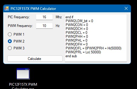
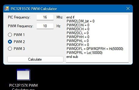
PIC12F157X PWM Calculator Software
PIC12F157X PWM Calculator PIC Frequency: 16 MHz PWM Frequency: 10 Hz PWM 1 PWM 2 PWM 3 Calculate end if PWM2LDM_bit = 0 PWM2CON = 0 PWM2DCH = 0 PWM2DCL = 0 PWM2PHH = 0 PWM2PHL = 0 PWM2OFH = 0 PWM2OFL = 0 PWM2PRH = Hi(50000) PWM2PRL = Lo(50000) end sub
in „Frage zu PIC12F1572“ · Mikrocontroller und Digitale Elektronik · · Screenshots
-
 Bild
Bild
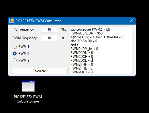
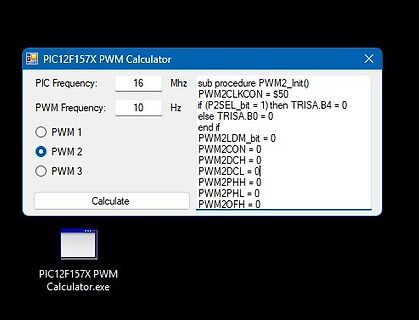
Software-Fenster eines PIC12F157X PWM Calculators
PIC12F157X PWM Calculator PIC Frequency: 16 Mhz PWM Frequency: 10 Hz PWM 1 PWM 2 PWM 3 Calculate sub procedure PWM2_Init() PWM2CLKCON = $50 if (P2SEL_bit = 1) then TRISA.B4 = 0 else if TRISA.B0 = 0 end if PWM2LDM_bit = 0 PWM2CON = 0 PWM2DCH = 0 PWM2DCL = 0 PWM2PHH = 0 PWM2PHL = 0 PWM2OFH = 0 PIC12F157X PWM Calculator.exe
in „Frage zu PIC12F1572“ · Mikrocontroller und Digitale Elektronik · · Screenshots
-
Datei
msp430x46x_tb_10.c
| 32kHz // --|RST XOUT|- // | | // | P2.2/TB1|--> CCR1 - 75% PWM // | P2.3/TB2|--> CCR2 - 25% PWM // | P3.4/TB3|--> CCR3 - 12.5% PWM // | P3.5/TB4|--> CCR4 - 6.26% PWM // | P3.6/TB5|--> CCR5 - 3.13% PWM // | P3.7/TB6|--> CCR6 - 1.566% PWM // // K. Quiring/ M. Mitchell
in „MSP430xG46x TimerB Capture Compare Register Funktion“ · Mikrocontroller und Digitale Elektronik ·
-
Datei
empfangen_uebung.c
wert1 = 0; if(pwm > 185) { wert1 = -(pwm-177); wert1 = ((wert1*4)+35); OCR1A = wert1; PORTB |= (1 << PB3); PORTB &= ~(1 << PB5); } if(pwm < 181) { wert1 = -(pwm-177); wert1 = ((wert1*4)+25); wert1 = -wert1; OCR1A = wert1
in „Probleme mit UART“ · Mikrocontroller und Digitale Elektronik ·
-
Datei
pwm8ch.asm
*********************************** RAM usage ****************************** .dseg .org SRAM_START pwm_val: ;brightness value, .byte 8 ;8 LEDs pwm_val_end: pwm_data: ;bit slice pattern, .byte 8 ;8 bit pwm_data_end: .cseg .list .listmac ;----------------------------------------------------------------
in „AVR Assembler-Frage“ · Mikrocontroller und Digitale Elektronik ·
-
 Bild
Bild
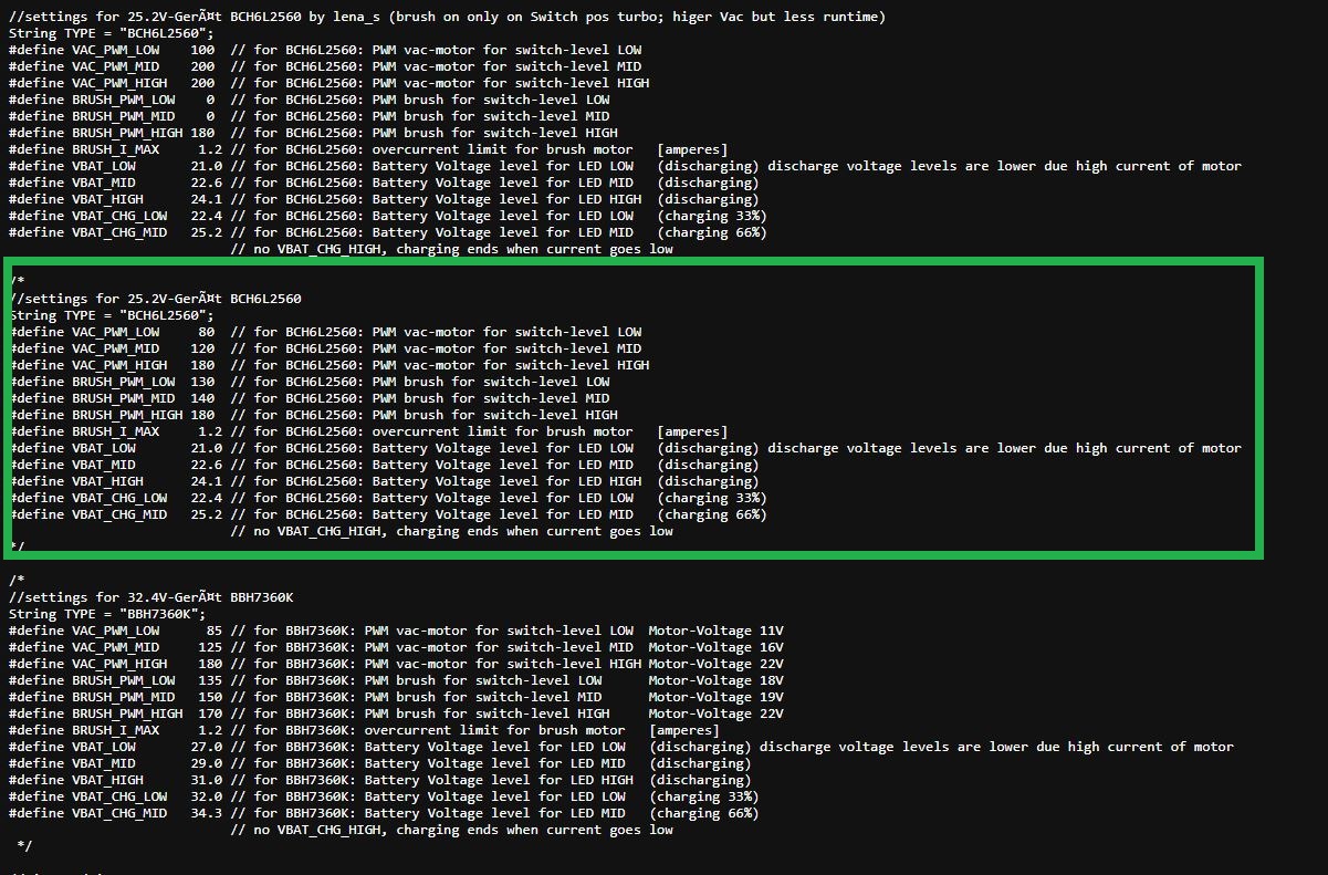
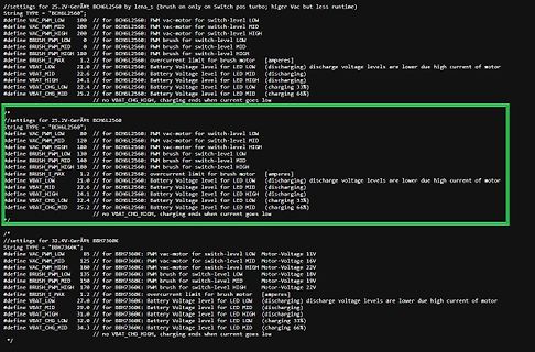
Konfigurationsdatei für PWM- und Batteriespannungswerte
//settings for 25.2V-Gerät BCHL2560 STRING type = "BCHL2560"; #define VAC_PWM_LOW 100 // for BCHL2560: PWM vac-motor for switch-level LOW #define VAC_PWM_MID 200 // for BCHL2560: PWM vac-motor for switch-level MID #define VAC_PWM_HIGH 200 // for BCHL2560: PWM vac-motor for switch-level
in „Bosch Athlet 25,2 V Akku 7 Stück Tauschen“ · Analoge Elektronik und Schaltungstechnik · · Screenshots
-
PDF
drv103.pdf
Cycle addition, adjustable PWM allows fine control of the power ● FULLY PROTECTED delivered to the load. DC-to-PWM output delay time and Thermal and Current Limit Shutdown with oscillator frequency are also externally adjustable.
in „PWM Signal wie stell ich das ein?“ · Mikrocontroller und Digitale Elektronik ·