Suchergebnisse für ""STM32""
Groppe * pic-projekte.de/Download/1-Wire-Projekt-V1_3.pdf * * Umgeschrieben zur Verwendung auf dem STM32 F4 Discovery * * von Malte Becker * Projekt-Seminar WS 12/13 */ // Includes #include "stm32 f4xx.h" #include "stm32 f4xx_gpio.h" #include "stm32 f4xx_rcc.h" #include "global_variables.h" // Sensor-Konfiguration
in
„1-Wire Stm32f4discovery“
·
Mikrocontroller und Digitale Elektronik
·
20.02.2013 14:22
Header */ /** ****************************************************************************** * @file stm32 f0xx_it.c * @brief Interrupt Service Routines. ****************************************************************************** * @attention * * <h2><center>© Copyright (c) 2019 STMicroelectronics
in
„LCD W204B-NLW“
·
Mikrocontroller und Digitale Elektronik
·
16.04.2019 19:46
/* * usart_stm32 f4xx.c * * USART/UART-Treiber * * $Date: 2019-03-24 09:25:14 +0100 (So, 24 Mrz 2019) $ * $Revision: 578 $ * * 15.05.2019 Nicolas */ #ifdef STM32 F4XX #include "usart.h" #include "hw_config.h" #include "myassert.h" #include "stm32 f4xx_usart.h" // Testbuffer #define DMA_BUFFERLEN 10 uint8_t dma_buffer[DMA_BUFFERLEN] = "Hallo!\n"; /** UART Initialisieren */ void usart_init(void) { USART_InitTypeDef USART_InitStructure; GPIO_InitTypeDef
in
„STM32: Sendepuffer für USART“
·
Mikrocontroller und Digitale Elektronik
·
18.05.2019 15:17
per copy und paste in das Feld eingefügt werden!) USE_STDPERIPH_DRIVER USE_FULL_ASSERT USE_ULPI_PHY STM32 F4XX USE_USB_OTG_FS HSE_VALUE=8000000 - Includes: (kann per copy und paste in das Feld eingefügt werden! mit den Anführungszeichen) "${workspace_loc:/${ProjName}}" "${workspace_loc:/${ProjName}/CMSIS}" "${workspace_loc:/${ProjName}/CMSIS/Include}" "${workspace_loc:/${ProjName}/STM32 F4xx_StdPeriph_Driver}" "${workspace_loc:/${ProjName}/STM32 F4xx_StdPeriph_Driver/inc}" "${workspace_loc:/${ProjName}/usb_vcp}" "${workspace_loc:/${ProjName}/usb_vcp/usb_cdc_lolevel}" - Optimization:
in
„Ambilight mit STM32F4discovery und TVP5150AM1“
·
Mikrocontroller und Digitale Elektronik
·
18.08.2014 09:45
TX/WKUP +3V VBAT CLKOUT 24 PA1/USART2_RTS/USART4_RX VDD33 25 PA2/USART2_TX +1V8 VDD18 REFCLK VDD18 STM32 F407VX +3V VDDIO NC N GND U$1G$2 G 26 PA3/USART2_RX 27 VSS2 28 VDD2 29 PA4/SPI1_NSS/SPI3_NSS/USART2_CK 30 31 PA5/SPI1_SCK 32 PA6/SPI1_MISO 33 PA7/SPI1_MOSI 34 PC4 35 PC5 36 PB0 37 PB1 38 PB2/BOOT1 39
in
„STM32F4 USB High Speed VCP mit USB3320 PHY“
·
Projekte & Code
·
24.12.2013 14:49
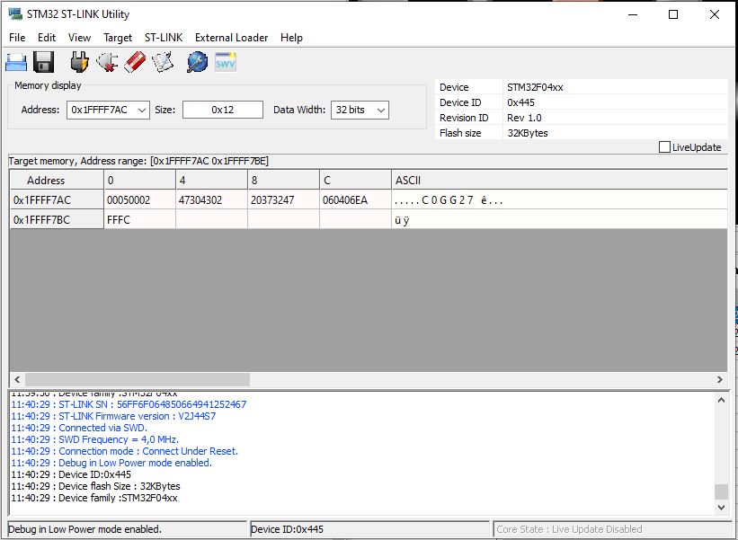
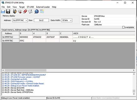
Bild
STM32 ST-LINK Utility
Memory display
Device STM32 F04xx
Device ID 0x445
Revision ID Rev 1.0
Flash size 32KBytes
Address: 0x1FFF7AC
Data Width: 32 bits
Target memory, Address range: [0x1FFF7AC 0x1FFF7BE]
Address
in
„STM32F042 gecloned aber verhält sich seltsam“
·
Mikrocontroller und Digitale Elektronik
·
17.01.2025 12:40
·
Screenshots
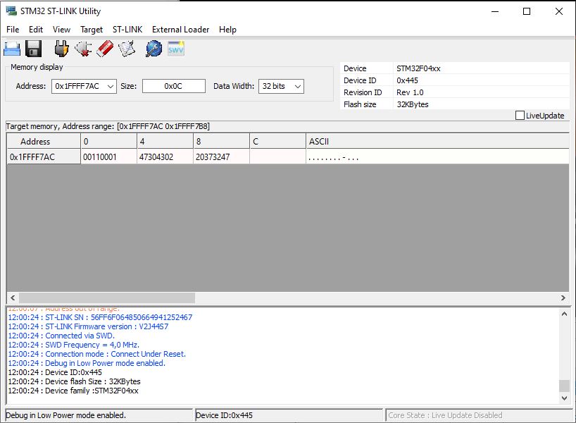
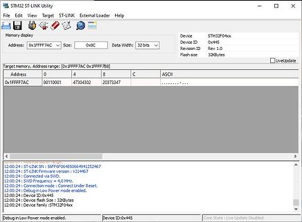
Bild
STM32 ST-LINK Utility
Device STM32 F04xx
Address: 0x1FFFF7AC
Size: 0x0C
Data Width: 32 bits
Device ID 0x445
Revision ID Rev 1.0
Flash size 32KBytes
Target memory, Address range: [0x1FFFF7AC 0x1FFFF7B8]
Address
in
„STM32F042 gecloned aber verhält sich seltsam“
·
Mikrocontroller und Digitale Elektronik
·
17.01.2025 12:42
·
Screenshots
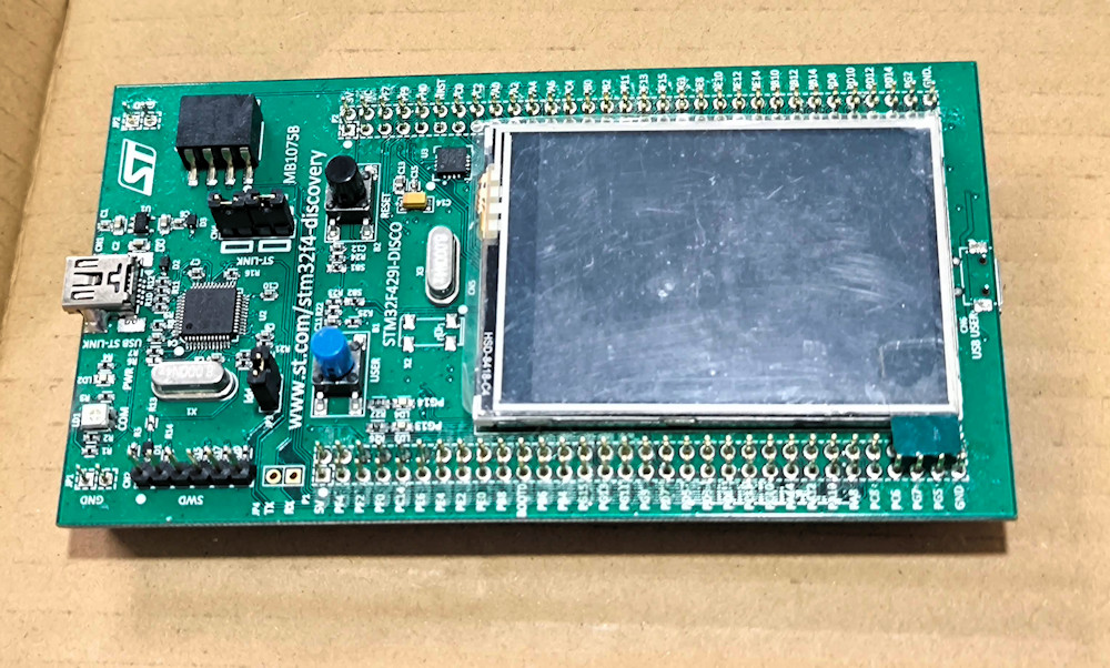
Bild
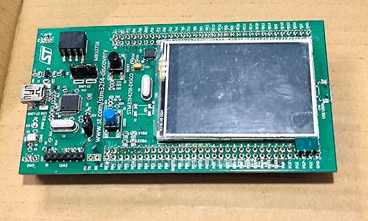
STM32 F429-DISCO, www.st.com, ST-LINK, USB USER, USER, SWD, GND, PG14, PG13, PG12, PG11, PG10, PG9, PG8, PG7, PG6, PG5, PG4, PG3, PG2, PG1, PG0, PA15 bis PA0, PB15 bis PB0, PC15 bis PC0, PH14, PH13, PH12,
in
„[V] Diverse Evaluation-Boards - ca. 2014-2016“
·
Markt
·
05.02.2025 08:46
·
Platinenfotos
Bild
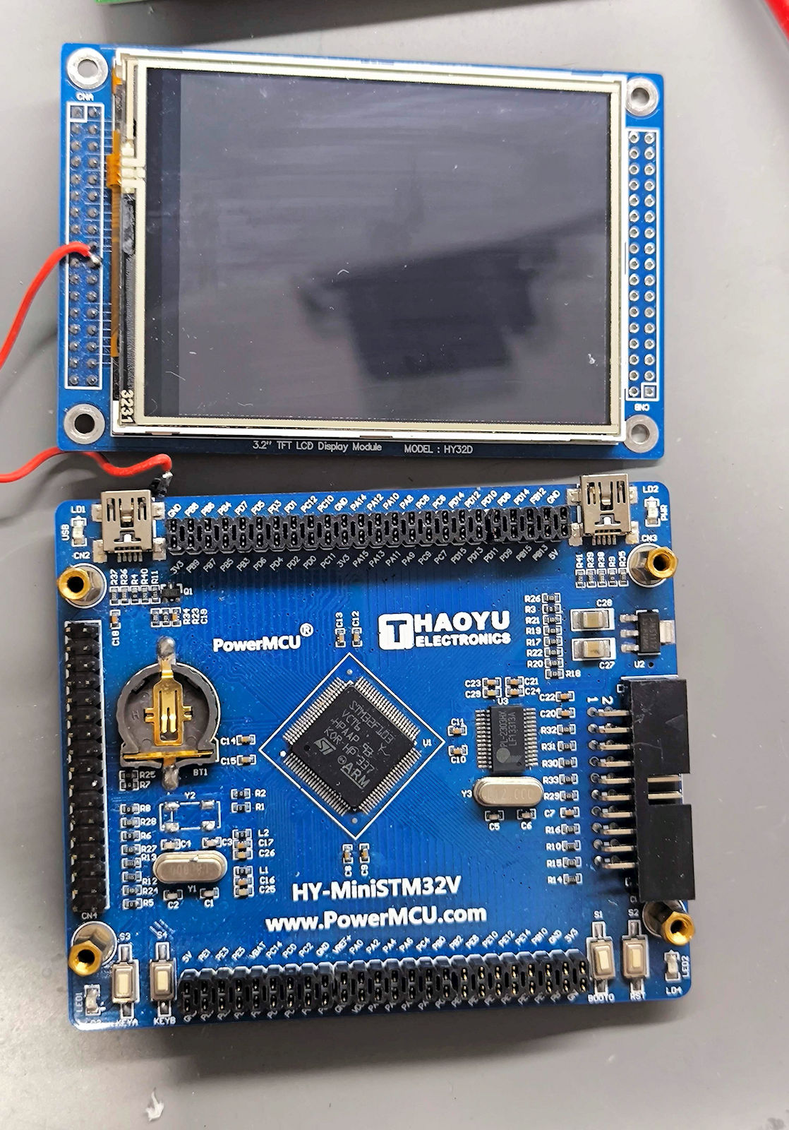
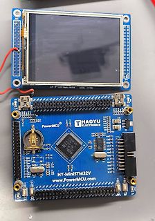
3.2" TFT LCD Display Module MODEL: HY32D
PowerMCU
THAOYU ELECTRONICS
STM32 F407VGT6
ARM
HY-MiniSTM32 V
www.PowerMCU.com
in
„[V] Diverse Evaluation-Boards - ca. 2014-2016“
·
Markt
·
06.03.2025 11:11
·
Platinenfotos
Bild
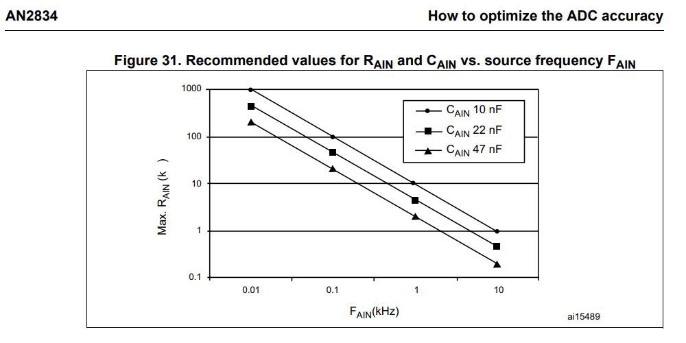
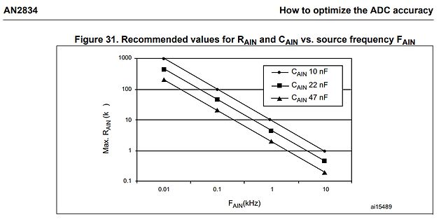
AN2834 How to optimize the ADC accuracy Figure 31. Recommended values for RAIN and CAIN vs. source frequency FAIN Max. RAIN ( k ) 1000 100 10 1 0.1 0.01 0.1 1 10 FAIN(kHz) CAIN 10 nF CAIN 22 nF CAIN 47 nF ai15489
in
„Attiny85 ADC Eingangswiderstand - wie hoch“
·
Mikrocontroller und Digitale Elektronik
·
24.01.2024 09:00
·
Diagramme
Bild
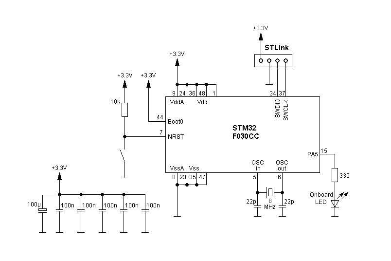
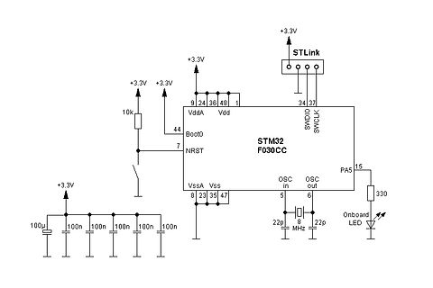
+3.3V STLink 34 37 SWDIO SWCLK 9 24 36 48 1 Vdd VddA Vdd Boot0 44 7 NRST STM32 F030CC PA5 15 330 Onboard LED 8 23 35 47 Vss VssA OSC in OSC out 5 6 22p 8 MHz 22p 100µ 100n 100n 100n 10k
in
„Probleme mit STM32F030CC“
·
Mikrocontroller und Digitale Elektronik
·
07.02.2024 18:39
·
Schaltpläne
Bild
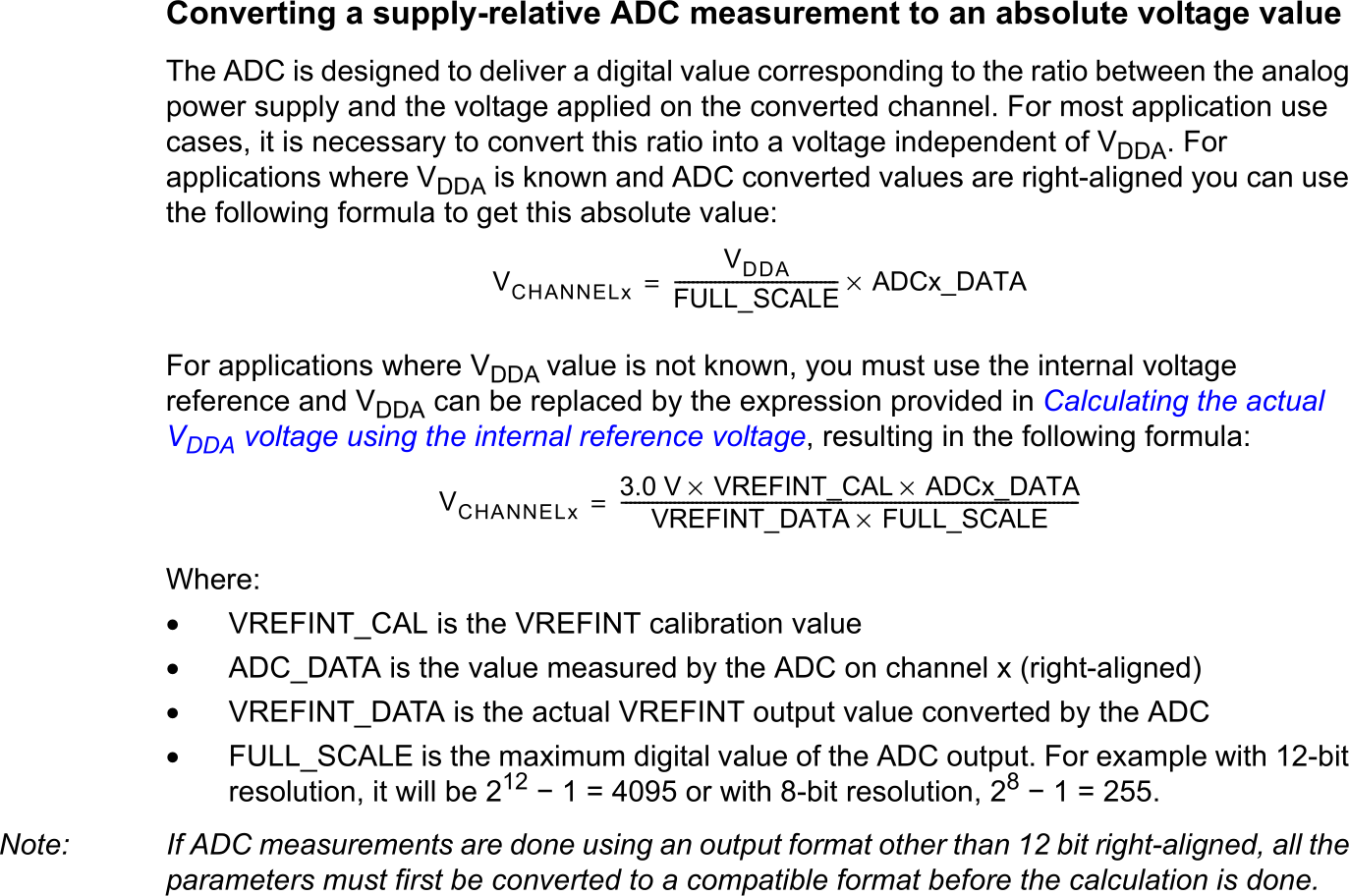
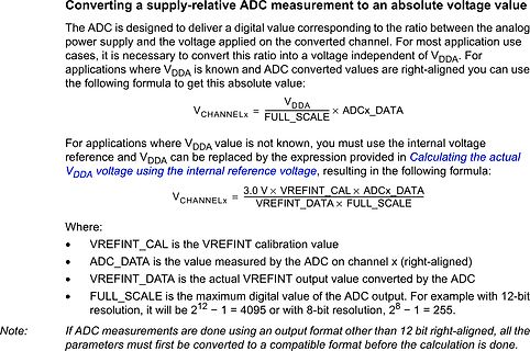
Converting a supply-relative ADC measurement to an absolute voltage value
The ADC is designed to deliver a digital value corresponding to the analog power supply and the voltage applied on the converted channel. For most application use cases, it is necessary to convert this ratio into a voltage independent of VDDA. For applications where VDDA is known and ADC converted values can use the following formula to get this absolute value:
VCHANNELx = (VDDA / FULL_SCALE) x ADCx_DATA
For applications where VDDA value is not known, you must use the internal voltage reference and VDDA can be replaced by the expression
in
„ADC - ungenaue Werte“
·
Analoge Elektronik und Schaltungstechnik
·
26.02.2024 10:36
·
Screenshots
Bild
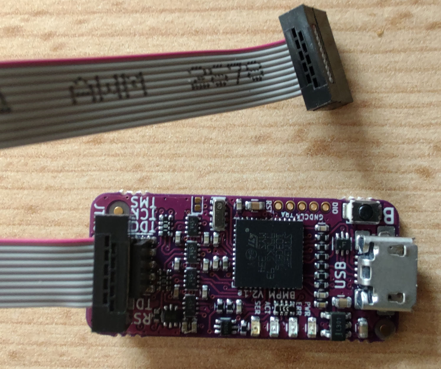
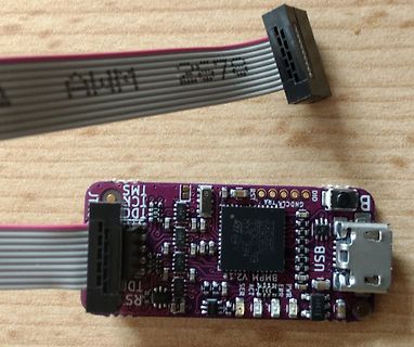
AWM 2575, TMS, TCK, TDC, GND, CLK, SDA, SCL, USB, BMPM V2.1, SER, PWR, GND, RST, TDO, TDI, TCK, TMS, TBD, RS
in
„10W Bitcoin miner mit 450GH/s für Raspberry Pi“
·
Projekte & Code
·
29.02.2024 13:36
·
Platinenfotos
Bild
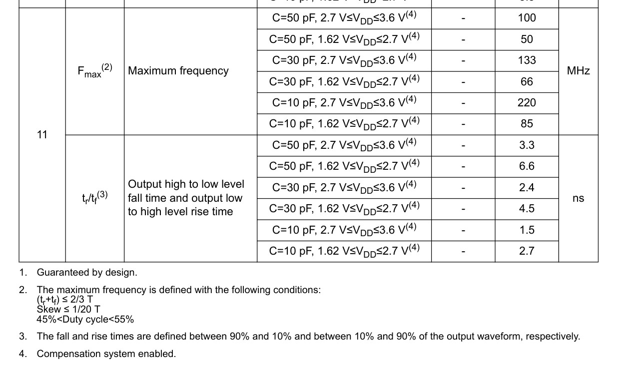
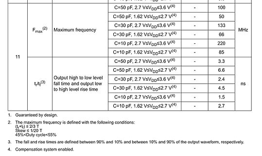
Fmax(2) Maximum frequency C=50 pF, 2.7 V<=VDD<=3.6 V(4) 100 C=50 pF, 1.62 V<=VDD<=2.7 V(4) 50 C=30 pF, 2.7 V<=VDD<=3.6 V(4) 133 MHz C=30 pF, 1.62 V<=VDD<=2.7 V(4) 66 C=10 pF, 2.7 V<=VDD<=3.6 V(4) 220 C=10 pF, 1.62 V<=VDD<=2.7 V(4) 85 tr/tf(3) Output high to low level fall time and output low to high level rise time C=50 pF, 2.7 V<=VDD<=3.6 V(4) 3.3 ns C=50 pF, 1.62 V<=VDD<=2.7 V(4) 6.6 C=30 pF, 2.7 V<=VDD<=3.6 V(4) 2.4 C=30 pF, 1.62 V<=VDD<=2.7 V(4) 4.5 C=10 pF, 2.7 V<=VDD<=3.6 V(4) 1.5 C=10 pF, 1.62 V<=VDD<=2.7 V(4) 2.7
in
„Gesucht Generator/Oszillator mit fester Frequenz 250 MHz“
·
Analoge Elektronik und Schaltungstechnik
·
22.07.2025 19:53
·
Screenshots
Bild
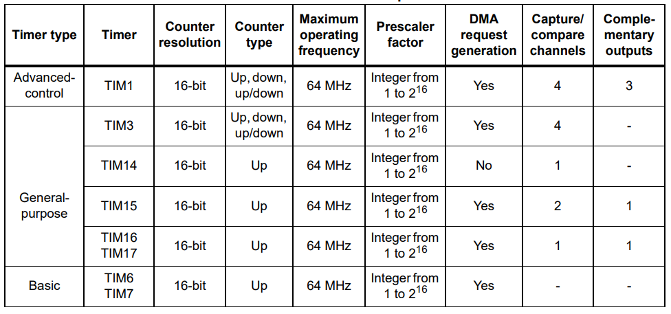
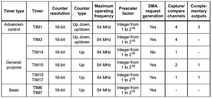
Timer type, Timer, Counter resolution, Counter type, Maximum operating frequency, Prescaler factor, DMA request generation, Capture/compare channels, Complementary outputs
Advanced-control, TIM1, 16-bit, Up, down, up/down, 64 MHz, Integer from 1 to 2^16, Yes, 4, 3
TIM3, 16-bit, Up, down, up/down, 64 MHz, Integer from 1 to 2^16, Yes, 4, -
General-purpose, TIM14, 16-bit, Up, 64 MHz, Integer from 1 to 2^16, No, 1, -
TIM15, 16-bit, Up, 64 MHz, Integer from 1 to 2^16, Yes, 2, 1
TIM16 TIM17, 16-bit, Up, 64 MHz, Integer from 1 to 2^16, Yes, 1, 1
Basic, TIM6 TIM7, 16-bit, Up, 64 MHz, Integer from 1 to
in
„RC-Signale einlesen - so einigermassen bulletproof?“
·
Mikrocontroller und Digitale Elektronik
·
22.04.2025 15:51
·
Screenshots
Bild
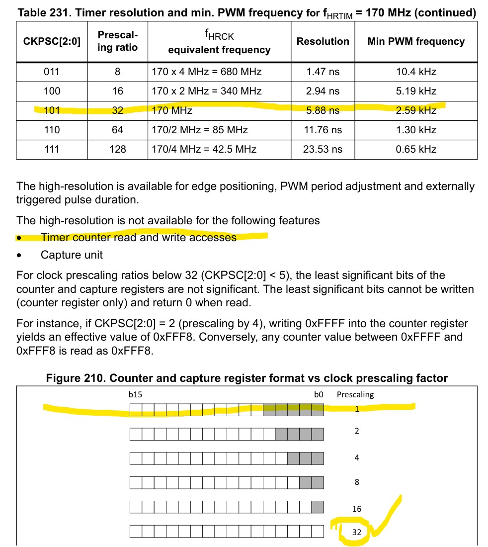
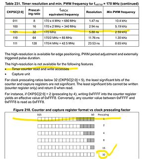
Table 231. Timer resolution and min. PWM frequency for fHRTIM = 170 MHz (continued)
CKPSC[2:0] Prescaling ratio fHRCK equivalent frequency Resolution Min PWM frequency
011 8 170 x 4 MHz = 680 MHz 1.47 ns 10.4 kHz
100 16 170 x 2 MHz = 340 MHz 2.94 ns 5.19 kHz
101 32 170 MHz 5.88 ns 2.59 kHz
110 64 170/2 MHz = 85 MHz 11.76 ns 1.30 kHz
111 128 170/4 MHz = 42.5 MHz 23.53 ns 0.65 kHz
Figure 210. Counter and capture register format vs clock prescaling factor
in
„Auflösung der Abtastung eines periodischen Signals mit ADC“
·
Mikrocontroller und Digitale Elektronik
·
04.08.2026 13:43
·
Screenshots
;/*****************************************************************************/ ;/* STM32 F10x.s: Startup file for ST STM32 F10x device series */ ;/*****************************************************************************/ ;/* <<< Use Configuration Wizard in Context Menu >>> */ ;/****
in
„STM32 SysTick“
·
Mikrocontroller und Digitale Elektronik
·
20.08.2009 20:35
Main-Auszug // Init clock system RCC_Configuration(); // NVIC configuration NVIC_Configuration(); // Config Miscellaneous Misc_Config(); // Config I2C-Bus I2C_Config(); // Config USART2 USART_Config(); - Ab hier ist PA01 high // External Interrupt Lines EXTI_Configuration(); // Config AD-Converter ADC_Config(); Misc_Config (Initialisierung der GPIOŽs) gekürzt void Misc_Config(void) { GPIO_InitTypeDef GPIO_InitStructure; // IO-Vorbereitung RCC_APB2PeriphClockCmd(RCC_APB2Periph_GPIOA | RCC_APB2Periph_GPIOB | RCC_APB2Periph_GPIOC | RCC_APB2Periph_GPIOD, ENABLE); GPIO_InitStructure.GPIO_Pin = GPIO_Pin_All;
in
„STM32 RTS-Problem bei USART2“
·
Mikrocontroller und Digitale Elektronik
·
16.12.2008 13:52
board (refer to stm32 _eval.h * to know about the boards supporting this memory). * It implements a high level communication layer for read and write * from/to this memory. The needed STM32 hardware resources (SDIO and *
in
„STM3210E EVAL SD-Controller SDIO + HiTOP“
·
Mikrocontroller und Digitale Elektronik
·
14.02.2011 16:13
// Anschluß einer LC-Anzeige 2x16 an das STM32 F4-Discovery-Board // lcd_init() muss als erste Funktion aufgerufen werden. Danach sollten // lcd_cmd() und lcd_zeichen() Befehle und Daten korrekt ausgeben. /* Das LCD-Modul wird im 4-Bit Modus betrieben
in
„LCD-Modul 2x16 am STM32F4Discovery-Board“
·
Projekte & Code
·
30.10.2012 19:34
to the target STM32 device used in your application */ #if !defined (STM32 F4XX) #define STM32 F4XX #endif /* Tip: To avoid modifying this file each time you need to switch between these devices, you can define the device
in
„STM32F0 Discovery und UART1“
·
Mikrocontroller und Digitale Elektronik
·
27.11.2013 13:08
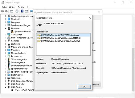
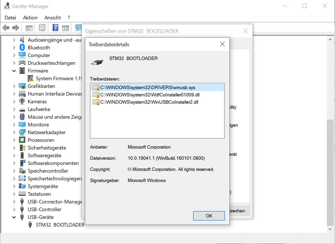
Bild
Geräte-Manager
Datei Aktion Ansicht ?
Eigenschaften von STM32 BOOTLOADER
Treiberdateidetails
STM32 BOOTLOADER
Treiberdateien:
C:\WINDOWS\system32\DRIVERSwinusb.sys
C:\WINDOWS\system32\WdfInstaller01009.dll
C:\WINDOWS\system32\WinUSBInstaller2.dll
Anbieter: Microsoft
in
„DFU UTIL & LIBUSB unter Windows“
·
Mikrocontroller und Digitale Elektronik
·
05.07.2023 10:38
·
Screenshots
Em D 72C R1 C2 e L L L S 1 SV2 20 1 SV3 10 01.03.2012 18:44:54 C:\Users\SuperK\13-Eagle\1-Projekte\STM32 F407Vx_Baseboard\STM32 F4-BASE.brd
in
„STM32F407 (100pin) Basisboard - Review bitte“
·
Mikrocontroller und Digitale Elektronik
·
01.03.2012 22:33
-------------------------------------------- * Linker script for running in internal FLASH on the STM32 F103C8 *----------------------------------------------------------------------------*/ OUTPUT_FORMAT("elf32-littlearm", "elf32-littlearm", "elf32-littlearm") OUTPUT_ARCH(arm) SEARCH_DIR(.) ENTRY(_reset
in
„uint64_t auf STM32F103“
·
Mikrocontroller und Digitale Elektronik
·
19.12.2019 19:17
ENTRY(_reset) MEMORY { /* memory map of STM32 F100 */ Flash (rx): ORIGIN = 0x08000000, LENGTH = 256K SRAM0 (rwx): ORIGIN = 0x20000000, LENGTH = 64K } _stack_end = ORIGIN(SRAM0) + LENGTH(SRAM0); SECTIONS { .text : { _text_section_start = .; KEEP
in
„uint64_t auf STM32F103“
·
Mikrocontroller und Digitale Elektronik
·
19.12.2019 19:17
2 1 R 5 GND/3.3V E W 3 0 O 1 2 R 1 P IC1 C1 4 4 4 4 4 4 4 4 4 3 3 3 7 STM32 F102CB 1 1 4 4 4 4 4 4 4 4 4 3 3 3 736 36 0 2 2 35 35 1 3 3 34 34 3 1 4 4 33 33 C2 C Q 1 5 5 32 32 4 R 6 6 31 31 C 7 7 30 30 R4 8 8 29 29 9 9 28 28 10 10 27 27 11 11 26 26 12 12 25 25 1 1 1 1 1 1 1
in
„STM32F1 Grundbeschaltung“
·
Mikrocontroller und Digitale Elektronik
·
18.01.2012 15:53
/* Boxlib (c) 2021 by Malte Marwedel SPDX-License-Identifier: BSD-3-Clause */ #include <stdbool.h> #include <stdint.h> #include <stdio.h> #include <stddef.h> #include "boxlib/peripheral.h" #include "main.h" #include "boxlib/lcd.h" #include "boxlib/flash.h" #include "boxlib/spiGeneric.h" #include "spiPlatform.h" void PeripheralBaseInit(void) { GPIO_InitTypeDef GPIO_InitStruct = {0}; __HAL_RCC_GPIOA_CLK_ENABLE(); //Backlight, power off pin __HAL_RCC_GPIOB_CLK_ENABLE(); //SPI2 pins __HAL_RCC_GPIOC_CLK_ENABLE(); //FlashCs, Lcd A0, LcdCs HAL_GPIO_WritePin(GPIOC, FlashCs_Pin | LcdA0_Pin | LcdCs_Pin, GPIO_PIN_RESET
in
„STM32: SPI - HAL durch eigenen code ersetzen“
·
Mikrocontroller und Digitale Elektronik
·
13.05.2025 00:09
/*------------------------------------------------------------------------*/ /* STM32 F100: MMCv3/SDv1/SDv2 (SPI mode) control module */ /*------------------------------------------------------------------------*/ /* / Copyright (C) 2014, ChaN, all right reserved. / / * This software
in
„SD-Karte mit SPI: Warteroutinen“
·
Mikrocontroller und Digitale Elektronik
·
16.02.2018 17:51
to the target STM32 device used in your application */ #if !defined (STM32 F4XX) #define STM32 F4XX #endif /* Tip: To avoid modifying this file each time you need to switch between these devices, you can define the device
in
„STM32F4 SPI Problem“
·
Mikrocontroller und Digitale Elektronik
·
22.02.2018 12:03
/*------------------------------------------------------------------------*/ /* STM32 F100: MMCv3/SDv1/SDv2 (SPI mode) control module */ /*------------------------------------------------------------------------*/ /* / Copyright (C) 2014, ChaN, all right reserved. / / * This software
in
„STM32Fxxx: Frage zur Initialisierung mit der StdPeriphLib“
·
Mikrocontroller und Digitale Elektronik
·
18.03.2018 12:12
/*------------------------------------------------------------------------*/ /* STM32 F100: MMCv3/SDv1/SDv2 (SPI mode) control module */ /*------------------------------------------------------------------------*/ /* / Copyright (C) 2014, ChaN, all right reserved. / / * This software
in
„STM32Fxxx: Frage zur Initialisierung mit der StdPeriphLib“
·
Mikrocontroller und Digitale Elektronik
·
18.03.2018 14:14
/*------------------------------------------------------------------------*/ /* STM32 F100: MMCv3/SDv1/SDv2 (SPI mode) control module */ /*------------------------------------------------------------------------*/ /* / Copyright (C) 2014, ChaN, all right reserved. / / * This software
in
„STM32F103: Problem mit ChanFat und SD karte“
·
Mikrocontroller und Digitale Elektronik
·
19.03.2018 17:45
/*------------------------------------------------------------------------*/ /* STM32 F100: MMCv3/SDv1/SDv2 (SPI mode) control module */ /*------------------------------------------------------------------------*/ /* / Copyright (C) 2014, ChaN, all right reserved. / / * This software
in
„STM32F103: Problem mit ChanFat und SD karte“
·
Mikrocontroller und Digitale Elektronik
·
19.03.2018 20:57
/*------------------------------------------------------------------------*/ /* STM32 F100: MMCv3/SDv1/SDv2 (SPI mode) control module */ /*------------------------------------------------------------------------*/ /* / Copyright (C) 2014, ChaN, all right reserved. / / * This software
in
„STM32F103 diskio.c für Chan FatFs SD Karten Treiber“
·
Projekte & Code
·
20.03.2018 10:54
/*------------------------------------------------------------------------*/ /* STM32 F100: MMCv3/SDv1/SDv2 (SPI mode) control module */ /*------------------------------------------------------------------------*/ /* / Copyright (C) 2014, ChaN, all right reserved. / / * This software
in
„STM32F103: Problem mit ChanFat und SD karte“
·
Mikrocontroller und Digitale Elektronik
·
20.03.2018 13:39
/*------------------------------------------------------------------------*/ /* STM32 F100: MMCv3/SDv1/SDv2 (SPI mode) control module */ /*------------------------------------------------------------------------*/ /* / Copyright (C) 2014, ChaN, all right reserved. / / * This software
in
„STM32F103 diskio.c für Chan FatFs SD Karten Treiber“
·
Projekte & Code
·
20.03.2018 19:51
/*------------------------------------------------------------------------*/ /* STM32 F100: MMCv3/SDv1/SDv2 (SPI mode) control module */ /*------------------------------------------------------------------------*/ /* / Copyright (C) 2014, ChaN, all right reserved. / / * This software
in
„STM32F103 Bluepill mit 128kb lässt sich nicht flashen“
·
Mikrocontroller und Digitale Elektronik
·
12.04.2021 10:46
MEMORY { FLASH (rx) : ORIGIN = 0x00000000, LENGTH = 128K SRAM (rwx) : ORIGIN = 0x20000000, LENGTH = 20K } SECTIONS { . = 0x0; /* From 0x00000000 */ .text : { *(vectors) /* Vector table */ *(.text) /* Program code */ *(.rodata) /* Read only data */ } > FLASH . = 0x20000000; /* From 0x20000000 */ .data : { __data_load = LOADADDR (.data); __data_start = .; *(.data) /* Data memory */ __data_end = .; } > SRAM AT > FLASH .bss : { __bss_start = .; *(.bss) /* Zero-filled run time allocate data memory */ __bss_end = .; . = ALIGN (8); _end = .; } > SRAM AT > FLASH } /* End of allocated SRAM _end */ PROVIDE
in
„Problem mit malloc() + arm-none-eabi-gcc + newlib“
·
Mikrocontroller und Digitale Elektronik
·
23.01.2017 15:02
#include <stdint.h> #include "Pipe.h" #include "stm32 f030x6.h" #include "stm32 f0xx_hal.h" Pipe<32, uint8_t> ReceiverQueue; Pipe<32, uint8_t> SendQueue; extern UART_HandleTypeDef huart1; bool s_IsSending_bt = false; uint8_t s_EchoCnt_u8 = 0U; const uint32
in
„STM32F030 ParityError nur bei aktiviertem RXNEIE?“
·
Mikrocontroller und Digitale Elektronik
·
04.07.2016 10:12
! + *!/ +, + - ) !(--+! ( .+ ! *5 *(-/ +, +- *(- !! "# $ $ " $ $ % $ $ & $ % $ +, +- *(- $ ' $ & $ $ $ $ % $ % $ $ 7 5+ .+ ! *5 *(-/ , - & !4$% * 5 / / 0 @ B 2 !4$% * 5 2 $ 0 @ B' 2 & /6 $"! ' + !4$% * 5 C @ B /6 $" ! ) * !4$% * 5 !> 1 >8 0 $> ) * 0 @ B ! " ) ./0 !4$% * 5 ? 1 $! 0 @ B ## $ ## E *$K#8*$K. @* $K# & 8* $K. B *%K#8*%K. @* %K# & 8* %K. B 0 ( * $ & % * % & % ! -/ !4$% * 5 9 ! % * @ B $ 8 $$" !H" ' 4 43 & $> + 9 ) * 1 $$8/6 $"$ 1 $!8/6 $" ' J 9 ) * 0/ !4$% * 5 ) * ) * 4 " $! ) * @$! 8 B & & 8 >; #< + & 1.. 9 ) * 1 $$8/6 $"$ 1 $!8/6 $" ' J 9 ) * .!/ !4$% * 5 $!" & 0 & $5 ' & & ' & & &
in
„STM32 USB Virtual COM Port“
·
Mikrocontroller und Digitale Elektronik
·
19.01.2011 14:44
//-------------------------------------------------------------- // File : stm32 _ub_spi1.c // Datum : 29.10.2013 // Version : 1.1 // Autor : UB // EMail : mc-4u(@)t-online.de // Web : www.mikrocontroller-4u.de // CPU : STM32 F429 // IDE : CooCox CoIDE 1.7.4 // GCC : 4.7 2012q4 /
in
„STM32F429 - kein Takt am SPI“
·
Mikrocontroller und Digitale Elektronik
·
24.06.2014 11:23
// Anschluß einer LC-Anzeige 2x16 an das STM32 F4-Discovery-Board // lcd_init() muss als erste Funktion aufgerufen werden. Danach sollten // lcd_cmd() und lcd_zeichen() Befehle und Daten korrekt ausgeben. /* Das LCD-Modul wird im 4-Bit Modus betrieben
in
„Frequenz- und Pulsweitenmessung mit STM32F407“
·
Projekte & Code
·
26.11.2014 12:30
************************************************ */ /** @addtogroup CMSIS * @{ */ /** @addtogroup stm32 f103xb * @{ */ #ifndef __STM32 F103xB_H #define __STM32 F103xB_H #ifdef __cplusplus extern "C" { #endif /** @addtogroup Configuration_section_for_CMSIS * @{ */ /** * @brief Configuration of the Cortex-M3
in
„System Workbench für STM32 Anfängerfragen“
·
PC Hard- und Software
·
24.10.2023 18:33
serial: 303030303030303030303031 flash: 65536 (pagesize: 256) sram: 32768 chipid: 0x429 dev-type: STM32 L1xx_Cat_2 root@linux-kwm1:~ >st-info --chipid 0x0429 st-flash --connect-under-reset write /dev/shm/QAXE/FW/qaxe/firmware/fw-rev2/qaxe-rev2.bin 0x8000000 >st-flash --connect-under-reset write /dev/shm
in
„10W Bitcoin miner mit 450GH/s für Raspberry Pi“
·
Projekte & Code
·
04.03.2024 19:31
D XTAL1 5 46 SWDIO PD0 PA13 XTAL2 6 PD1 PA14 49 SWCLK C18 100n +5V +5VA 54 50 10µ C23 L2 PD2 PA15 STM32 F103RCTx 47µ 8 26 LED0 1 2 9 PC0 PB0 27 LED1 PC1 PB1 GNDD GNDD 4 3 U7 H10 H11 H12 H13 H14 H15 H16 H17 10 PC2 PB2 28 FMT 6 11 55 BUTTON_0 SCK D A 1 5 C14 C15 C16 PC3 PB3 7 LRCK V C VRef 1 C 100µ 10µ
in
„STM32F103 und I2S Probleme“
·
Mikrocontroller und Digitale Elektronik
·
05.09.2019 16:23
Multi Media Development Board Size Number Revision A4 Date: 5-Mar-2011 Sheet of File: F:浩宇电子 \HY-SmartSTM32 \HY-SmaTra3w2n.DBdyb: 1 2 3 4 1 2 3 4 5 6 D U1 D VSYNC 23 81 FSMC_D2 CAM_VSYNC IR_IN 24 PA0/WKUP/USART2_CTS/ADC123_IN0/TIM5_CH1/TIM2_CH1_ETR/TIM8_ETR PD0/FSMC_D2/CAN_RX 82 FSMC_D3 FSMC_D2 IR_IN U2_TX
in
„STM32 can Message“
·
Mikrocontroller und Digitale Elektronik
·
15.07.2013 22:21

 Bild
Bild
 Bild
Bild
 Bild
Bild
 Bild
Bild
 Bild
Bild
 Bild
Bild
 Bild
Bild
 Bild
Bild
 Bild
Bild
 Bild
Bild
 Bild
Bild
 Bild
Bild