-
PDF
light-control-v2.2.pdf
1 2 3 4 5 6 7 8 A A 5 5 + + + V 0 k R 1 R 1 H X1-5 1 0 L 1 MEGA8-P 1 23 1 K 5 PC6(/RESET) PC1(ADC1) 24 2 0 R Spannungsmessung 22 GND PC2(ADC2) 25 5 21 AREF PC3(ADC3) 26 3 B 20 AVCC PC4(ADC4/SDA) 27 C4 B C3 C7 PC5(ADC5
in „Projekt Tauchlampe“ · Mikrocontroller und Digitale Elektronik ·
-
Datei
fuse.c
4) - - . | * | o--------------o . . . . . . . . . . . | * | . (a) . E B C . (a) . . . . . . (b) . . | EBC of 2n2222 * | . . . . . . . . . . . . . o--B--o . | * +=====================================================+ * (p)(p) join (p)(p) during programming * * SDO
in „Attiny85 neu verfust?“ · Mikrocontroller und Digitale Elektronik ·
-
Bild
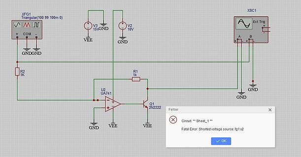
Schaltplan mit Fehlermeldung in Simulationssoftware
XFG1 Triangular(100 99 100m 0) V3 15VGND V2 10V XSC1 Ext Trig + - A B + - R2 1k GND GND R1 1k GND GND U2 UA741 Q1 2N2222 Fehler Circuit: ** Sheet_1 ** Fatal Error: Shorted voltage source: fg1:v2 OK
in „Simulation : Wieso hat V2 Kurzschluss ?“ · Analoge Elektronik und Schaltungstechnik · · Screenshots
-
Bild
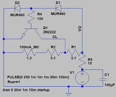
Schaltplan einer Transistor-Schaltung mit SPICE-Befehlen
D2 MUR460 R4 150 Q1 2N2222 CL VO D1 MUR460 R2 5.1 R1 5.1 100mA_Mtr 1.3 R5 10 V1 C1 100uF PULSE(0 250 1m 1m 1m 20m 100m) Rser=1 .tran 0 30m 1m 10m startup
in „einfache Drehspul-Meßinstrument Überlastschutzschaltung“ · Analoge Elektronik und Schaltungstechnik · · Schaltpläne
-
Bild
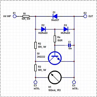
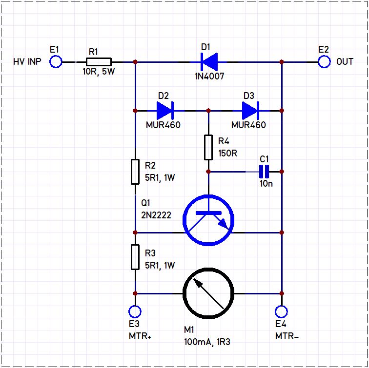
Schaltplan einer Motorsteuerung mit Transistor
E1 HV INP R1 10R, 5W D1 1N4007 E2 OUT D2 MUR460 D3 MUR460 R4 150R C1 10n R2 5R1, 1W Q1 2N2222 R3 5R1, 1W E3 MTR+ M1 100mA, 1R3 E4 MTR-
in „einfache Drehspul-Meßinstrument Überlastschutzschaltung“ · Analoge Elektronik und Schaltungstechnik · · Schaltpläne
-
Bild
Screenshot einer Webseite über eine Empfangsschleifenantenne
Rubrik "Technische Themen" der Juni-Ausgabe 1986 von RadCom... Anzahl der Transistoren: BC547, 2N2222, 2N5109, BFW16A, 2N3688
in „Text als.JPG in Dokument Umwandeln?“ · PC Hard- und Software · · Screenshots
-
Bild
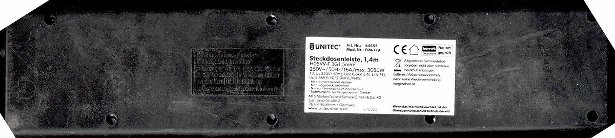
Rückseite einer Steckdosenleiste mit Typenschild
UNITEC Art. Nr.: 44555 Mod. Nr.: EIM-179 Steckdosenleiste, 1,4m H05VV-F 3G1,5mm² 250V~/50Hz/16A/max. 3680W T3, Uc 255V~, Uo 6,6V (L-N, L/N-PE) bis zur Vorwahrung in Trockenräumen darf das Gerät nicht länger als 1 Jahr gelagert werden. Nicht hintereinander stecken. Nur zur Verwendung mit geerdetem
in „Sicherheitschraube: Name? Werkzeug?“ · Offtopic · · Fotos
-
Bild
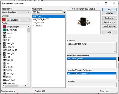
Screenshot einer Bauelement-Auswahl in einer Elektronik-Software
IDEALIZED 555 TIMER Modellhersteller/-kennung: IIT / IDEAL TIMER Hersteller/Typ des Gehäuses: IPC-2221A/2222 / DIP-8 Hyperlink: Bauelemente: 4 Suche: 555 Filter: aus
in „Simulation einer NE555 Ausschaltverzögerung in Multisim funktioniert nicht“ · Analoge Elektronik und Schaltungstechnik · · Screenshots
-
Bild
Handgezeichneter Schaltplan
T-6,3A, B, S, +R, P2, R1, R2, R3, R4, R5, R6, R7, R8, R9, R10, R11, R12, R13, R14, R15, C3, C5, BC547, BC720, BC640, 1000, 10k, 22k, 47k, 470, 100n, 220uF, 12uF, 2N2222, 2N3904, 2N3906, 2N5551, 2N5552, 2N5401
in „Datenblatt und Funktionsbeschreibung für Operationsverstärker ßA 741 gesucht“ · Analoge Elektronik und Schaltungstechnik · · Schaltpläne
-
PDF
CAN.pdf
°C 9 4.2566 601 5 02 02 01 03 FF -B2- 10 4.3793 601 7 03 00 00 01 A1 01 7E H1 VL: 54.3°C Raum?: 19.8°C 11 4.4999 601 5 04 02 02 03 FF -B3- 12 4.6222 601 7 05 00 01 03 FF 03 FF -H2- 13 7.9127 601 5 00 01 00 01 33 Aussen: -13.0°C 14 8.0341 601 5 01 02 00 00 D4 Boiler1:
in „Sommerauer-Lindner canbus Steuerung Hackgut“ · Haus & Smart Home ·
-
Bild
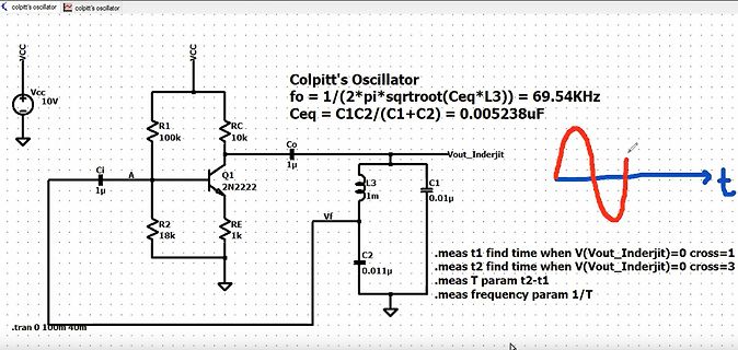
Schaltplan und Berechnungen eines Colpitt's Oszillators
= 1/(2*pi*sqrtoot(Ceq*L3)) = 69.54KHz Ceq = C1C2/(C1+C2) = 0.005238uF VCC 10V R1 100k RC 10k Ci 1u A Q1 2N2222 R2 18k RE 1k Co L3 1m C1 0.01u C2 0.011u Vf t .meas t1 find time when V(Vout_Inderjit)=0 cross=1 .meas t2 find time when V(Vout_Inderjit)=0 cross=3 .meas T param t2-t1 .meas frequency param
in „LTspice-Anfänger Oszillator: Warum anderes Vout?“ · Analoge Elektronik und Schaltungstechnik · · Screenshots
-
PDF
Amp-30W-25-110MHz-BLF244-1.pdf
of turns required can be calculated with the following formula (3): L = A × N 2 (10) L A = -.4 × π × r (11) L Σl A in which: A L is the inductance in (nH) −1 ∑/A is the core constant in (mm ) given in (3) N is the number of turns r is the relative permeability (120 for grade
in „20MHz - 200MHz Isolator bzw. Zirkulator“ · HF, Funk und Felder ·
-
Thread
Eigenbautastköpfe
www.holmea.demon.co.uk/Avalanche/Avalanche.htm Dies ist eine Liste von denkbaren Transistoren dafür. 2N2222 TO-18 145V 500ps 2N1613 TO-5 140 500 2N2219 TO-5 130 500 2N4123 TO-92 170 400 2N3904 TO-92 135 400 2N5770* TO-92 45 400 PN3646 TO-92 90 300 2N3646 TO-106 85 300 MBT5179 SOT-23 50 275 2N2369A
see it in a single ended probe application. But in a differential probe used with a few hundred volts of common mode, it can lower you CMRR to only a couple hundred to one. The design of the attenuator network is
Analoge Elektronik und Schaltungstechnik ·branadic · ·550 Antworten
-
PDF
rps1203_schematic.pdf
5 3 2 N Q 2 A 8 .tran 0 0.1 0 0 D1 X R1 1 T Out Q Z D4 MBR20100CT 100 V1 R2 1k R3 KDZ12B SINE(0 17 50 0) R4 R5 V2 5k1 27k 510 Q3 Regelung C1 C2 C4 BC337-25 D3 R11 SINE(0 17 50) D2 3300µ 3300µ 47µ R=10-(99*time) R6 R12 1N4148 MBR20100CT 200 5k1 Q4 Begrenzung 2N2222 C3 R8 C5 R7 10µ 5k1 270 100n D5 R9 1N4148 D6 27k D7 R10 1N4148 1N4148 1k --- Z:\Eigene Schaltungen\Regulated Power Supply RPS 1203\rps1203.asc ---
in „Netzteil Samlex RPS 1203 Reparatur“ · Analoge Elektronik und Schaltungstechnik ·
-
PDF
d6a9b561-b36e-41ba-960d-979f019b7a6f.pdf
GND V 1 1 1 U10 1 RLY1 I I I 2 2 P P P 1 1 12V+ g 3 2 _ _ _ r Q4 3A sicherung 12V_GESCHALTET M M M 2060-452/998-404 e R 2N2222AU W W W Wago 2 pin connector t T 2 F5 1 5 P P P Max 9A n C E A E L T QF1206F3A00T l S L I 4 1 e B C E R 1 2 3 SRD-05VDC-SL-C R25 R21 R23 R22
in „Bitte um Hilfestellung beim Platinen Layout“ · Platinen ·
-
PDF
LGP42-10LF_EAY60869402_PLHF-L923A.pdf
ONSEMI YAGEO KAMAYA 92 4 2 Pcs LB602 LB604 RES FLAT 0J 1/4W(3216) RESISTOR-SMD PILKOR SAMSUNG ROHM MMBT2222A , SOT-23 ONSEMI 93 4 2 Pcs Q201 Q204 KTN2222AS, SOT-23 CHIP-TR KEC KST2222A , SOT-23 FAIRCHILD FDD5614P TO-252 FAIRCHILD 94 4 1 Pcs Q203 NTD20P06L TO-252 FET-SMD ONSEMI 95 4 1 Pcs Q502 KTC3551, SOT
in „LG Inverter Kapazitator abgebrannt“ · Analoge Elektronik und Schaltungstechnik ·
-
PDF
6047319.pdf
204- 35,30 27,12 22,02 point 6430 TMS320F240PQ TEX PQFP132 20 20 32k 1088 28 3x16/WD SCI/SPI 16x10b A- 1 349- 44,70 38,00 33,53 FLASH D/PWM 2143 TMS320F243PGE TEX PQFP144 20 20 8K 544 32 2x16/WD SPI/CAN 8x10b A-D/PWM 1 356- 35,70 29,34 24,91 FLASH 6216 1-25 26- 101+ 100 TMS320LF2403APAGA TEX TQFP64 40
in „Schnelle FFT in Assembler“ · Digitale Signalverarbeitung / DSP / Machine Learning ·
-
PDF
ZX5T851A.pdf
18 30 mV I =100mA, I =5mA* CE(SAT) C B 40 55 mV C=1A, IB=100mA* 45 65 mV C =1A, B =50mA* 95 130 mV I=2A, I =50mA* C B 170 210 mV I=5A, I =200mA* C B Base-emitter saturation voltage VBE(SAT) 950 1050 mV IC=4A, B =200mA* Base-emitter turn-on voltage VBE(ON) 840 950 mV IC=4A, VCE=1V* Static forward current transfer ratio hFE 100 200 IC=10mA, V CE=1V* 100 200 300 I=2A, V =1V* C CE 55 105 C=5A, VCE=1V* 20 40 C =10A, CE=1V* Transition frequency T 130 MHz I C100mA, V CE=10V
in „Ersatz für MPSA06 Transistor gesucht“ · Analoge Elektronik und Schaltungstechnik ·
-
Datei
Zusammenschnitt.txt
"1N2222" Bat. 8.9V OK Testen... NPN EBC=321 B=334 Uf=.72V Bat. 8.9V OK Testen... NPN EBC=321 B=334 Uf=.73V ******************************** "BC558" Bat. 8.9V OK Testen... PNP EBC=321 B=178 Uf=.77V *********
in „Transistortester AVR - Hardware“ · Mikrocontroller und Digitale Elektronik ·
-
Datei
Scan_iomega.xml
"1.03" scanner="nmap" version="5.00" startstr="September 12, 2009 - 10:16" args="nmap -sS -sU -T4 -A -v -PE -PP -PS21,22,23,25,80,113,31339 -PA80,113,443,10042 -PO --script all 192.168.2.100"><scaninfo services="1,3-4,6-7,9,13,17,19-26,30,32-33,37,42-43,49,53,70,79-85,88-90,99-100,106,109-111,113,119,125,135,139,143
in „NAS Konfigurationswebseite lässt sich nicht öffnen“ · PC Hard- und Software ·
-
PDF
6300_RM-217_RM-222_schematics.pdf
Sleepclock oscillator L9 CrI VDRAM M11 1 K9 CrO VIO D12 R2070 C2202 R2251 C2203 C2205 C2207 B2200 J2222 L8 G11 1n0 US 100k 1n0 1n0 1n0 VBack VR1 47k 2 R2216 M10 HV VRFC G12 2M2 G2200 C2208 32.768kHz J11 VSIM2 C9 GND GND GND GND GND GND 27p C2209 Backup WDDis 22p GND VRCP1 A10 GND GND GND battery GND VRCP2 C10 0 M4 AudClk TM L10 GND C2221 C2222 C2220 C2213 C2214 C2215 C2219 C2216 C2217 1 A4 Gnd1 D11 EarDaL K12 GND 1u0 1u0 1u5 1u5 1u5 1u5 1u5 1u5 1u5 2 B4 EarDaR Gnd2 GND DIG_AUDIO(5:0) 3 B5 MicData Gnd3 B8 GND 4 3 J2204 A3 PMARP Gnd4 K6 GND
in „Nokia 6300 Display“ · Mikrocontroller und Digitale Elektronik ·
-
PDF
Liteon_Water_Clear_3mm_LEDs.pdf
LTL1CHKXKNNSERIES Spec No.: DS20-2000-343 Effective Date: 08/22/2000 Revision: - LITE-ON DCC RELEASE BNS-OD-FC001/A4 LITE-ON Technology Corp. / Optoelectronics No.90,Chien 1 Road, Chung Ho, New Taipei City 23585, Taiwan, R.O.C. Tel: 886-2-2222-6181 Fax: 886-2-2221-1948 / 886-2-2221-0660 http://www.liteon.com/opto
in „suche "ulta low current" 3mm LEDs“ · Analoge Elektronik und Schaltungstechnik ·
-
Thread
Eigenbau Dipmeter (DipIt-inspiriert)
> of the shape (a peak or a dip) to be interpolated. Only a > section of the measured data vector was used to make the > regression model because the range of the measured frequency > sweeps was relatively wide
fact that a > "Phase Detector" is simply a multiplier.
HF, Funk und Felder ·qrp-gaijin · ·168 Antworten
-
Datei
cam.c
0x2200, 0x11 ); CamSetReg( 0x2203, 0x11 ); DelayMs( 1400 ); CamSetReg( 0x2200, 0x45+8 ); CamSetReg( 0x2222, 1 ); // jpg bypass CamSetReg( 0x2600, 0x1 ); CamSetReg( 0x2210, 0x20 ); // line buffer enable // imager subsampling CamSetReg( 0x250a, 0x44+0x80 ); // imager subsample r2s6 h and v CamSetReg( 0x2230
in „pollin kamera au-85“ · Mikrocontroller und Digitale Elektronik ·
-
PDF
FMMT620.pdf
nA V =5.5V EBO EB Collector Emitter Cut-Off Current CES 100 nA VCES=80V Collector-Emitter Saturation VCE(sat) 15 20 mV IC=0.1A, B =10mA* Voltage 45 60 mV IC=0.5A, B =50mA* 145 185 mV I =1A, I =20mA* 160 200 mV IC=1.5A, I =50mA* C B Base-Emitter Saturation Voltage VBE(sat) 0.86 1.0 V IC=1.5A, B =50mA* Base-Emitter Turn-On Voltage VBE(on) 0.82 0.95 V IC=1.5A, CE=2V* Static Forward Current Transfer hFE 200 450 IC=10mA
in „"intelligenter" Open-Kollektor?“ · Mikrocontroller und Digitale Elektronik ·
-
PDF
FMMT620.pdf
nA V =5.5V EBO EB Collector Emitter Cut-Off Current CES 100 nA VCES=80V Collector-Emitter Saturation VCE(sat) 15 20 mV IC=0.1A, B =10mA* Voltage 45 60 mV IC=0.5A, B =50mA* 145 185 mV I =1A, I =20mA* 160 200 mV IC=1.5A, I =50mA* C B Base-Emitter Saturation Voltage VBE(sat) 0.86 1.0 V IC=1.5A, B =50mA* Base-Emitter Turn-On Voltage VBE(on) 0.82 0.95 V IC=1.5A, CE=2V* Static Forward Current Transfer hFE 200 450 IC=10mA
in „Suche Transistoren mit kleinerem Spannungsübergang“ · Analoge Elektronik und Schaltungstechnik ·
-
PDF
Elektroschaltplan_V10.4.pdf
1 2 3 4 5 6 USB & MCU Spannungsversorgung Senosren A A File: USB & MCU.kicad_sch File: Spannungsversorgung.kicad_sch File:Sensoren.kicad_sch B B C C Sheet: / D D File: ESP32_PCB_D3.kicad_sch Title: Size: A4 Date: Rev: KiCad E.D.A. 9.0.6 Id: 1/4 1 2 3 4
in „Elektroschaltplan für Platine so funktionsfähig“ · Platinen ·
-
PDF
Elektroschaltplan_V11.pdf
1 2 3 4 5 6 USB & MCU Spannungsversorgung Senosren A A File: USB & MCU.kicad_sch File: Spannungsversorgung.kicad_sch File:Sensoren.kicad_sch B B C C Sheet: / D D File: ESP32_PCB_D3.kicad_sch Title: Size: A4 Date: Rev: KiCad E.D.A. 9.0.6 Id: 1/4 1 2 3 4
in „Elektroschaltplan für Platine so funktionsfähig“ · Platinen ·
-
PDF
Linvill_Feedback_Amplifier.pdf
. Cascade Linearization of the Common-BaseAmplifier To realize a practical substantial reduction in the emitter input resistance re, a cascade of two common-base amplifiers can be employed, Fig. 4 - Balanced Common-BaseAmplifier detecting the emitter signal voltage of the sec- Using Cascade Linearization ond amplifier (ve2, and then using a simple 1:1 widebandtransformertoinvertv andce2ductit tothebaseofthefirstamplifier. ShowninFig.3, this method results in a substantial reduction in theamplifierinputresistance: r e = e1 (5) hfe1−2 where
in „Richtwirkung einer Loopantenne erhöhen“ · HF, Funk und Felder ·
-
Thread
KiCAD ist im Kommen
Sonst hat man immer die Frage, welche Bezeichnung verwendet man? Die Funktionsbezeichnung des Pins (A, K, IN+, IN-, OUT, RESET, D, CLK, PB1, bei mehreren Einheiten pro Gehäuse auch gern A1, K1, A2, K2...) oder die (idealerweise JEDEC-)Positionsbeschriebung des Pads (1..x)? Typischerweise - und so ist
market penetration. Sorry to mention marketing in a tech environment, but that's what it is. So: what is the "market"? This has to be decided. But then: how and by whom? There are a lot of issues currently in discussion - at least in this forum
Platinen ·Lötauge · ·619 Antworten
-
Datei
Death_Bell_TLV493D.ino
* - Tischglocke * // * - Push-Pull DC Hubmagnet, 9 V * // * - Poti mit Schaltkontakt * // * - 2N 2222 NPN Transistor * // *********************************** #include <Wire.h> #include <TLx493D_inc.hpp> // Initialisiere den TLx493D-Sensor using namespace ifx::tlx493d; TLx493D_A1B6 sensor(Wire, TLx493D_IIC_ADDR_A0
in „Dead Bell Schaltplan und Arduiono Code“ · Mikrocontroller und Digitale Elektronik ·
-
PDF
LM393.pdf
. These comparators also have a unique characteristic in that the input common-mode voltage range includes ground, even though operated from a single power supply voltage. The LM393 series was designed to directly interface with TTL
in „40-390V HV DC-DC-Wandler vom Chinamann“ · Analoge Elektronik und Schaltungstechnik ·
-
PDF
ixTDM-Schematic-PCB-v1.1.pdf
R1616 PCOR11 PIP302 81CO88 LEDE1 NLED2 LED3 GND PIR16PIR16015_DE/!REP I U 3DE 3 A P I U 3 0 6 Termination PIP303 8235V Power LED 02 I2 82 10k TXD 4 D P0120 GND Header 3H 10u R1010 CR88 R1818 PIU304 DI D N 02 RS485 / RS232 GND PIR17PIR170PILD40A PILD40C Res Semi Res Semi Res Semi G R1515 VCC Res Semi GND 0150 I1150 8050 5 np 150 CLD44 U5 0 1A IA 3A NXX GND T 1C LD1D1 IC LD2D2 3C LD3D3 P I M 1 0P I M 1 0 2KEY GND GND GND P4P4 PIP401 P I M 1 0P I M 1 0 4 VDD PIP402 PB 4 Pin PC Header 2H VCC U2U2 GND D1D1 1: Black 2: Brown VCC PA MBRS1100 P2
in „Sammelbestellung? Mini-Platine: 3 Kanal Power-PWM mit ATMega+IR+RS485“ · Mikrocontroller und Digitale Elektronik ·
-
PDF
LTM8522.pdf
8522E Spec No.: DS-30-98-325 Effective Date: 06/23/2000 Revision: - LITE-ON DCC RELEASE BNS-OD-FC001/A4 LITE-ON Technology Corp. / Optoelectronics No.90,Chien 1 Road, Chung Ho, New Taipei City 23585, Taiwan, R.O.C. Tel: 886-2-2222-6181 Fax: 886-2-2221-1948 / 886-2-2221-0660 http://www.liteon.com/opto
in „(V) 7-Segment Display, 3-stellig, mit integrierter Elektronik (NOS)“ · Markt ·
-
PDF
LTM8522.pdf
8522E Spec No.: DS-30-98-325 Effective Date: 06/23/2000 Revision: - LITE-ON DCC RELEASE BNS-OD-FC001/A4 LITE-ON Technology Corp. / Optoelectronics No.90,Chien 1 Road, Chung Ho, New Taipei City 23585, Taiwan, R.O.C. Tel: 886-2-2222-6181 Fax: 886-2-2221-1948 / 886-2-2221-0660 http://www.liteon.com/opto
in „[V] 7-Segment Display, 3-stellig, mit integrierter Elektronik (NOS)“ · Markt ·
-
PDF
AS-I_Transponder.pdf
1 2 3 4 5 6 7 8 9 10 11 12 13 14 15 16 17 18 19 A V1 A VCC VDD asi_in0I40 P0V1040 P0V103737 asi_in1I41 P0V1041/T0) PA0 (ADCP0V103636 VCC A PB1 (T1) PA1 (ADCP0V1035 0 m asi_in2I42 P0V1042 35 V4 V5 0 1 V3 asi_in3I43 PB2P0V1043INT2) PA2 (ADCP0V103434 1
-
PDF
P-FET.pdf
Drain-Source Voltage VDSS 20 V Gate Source Voltage V ⫾12 V GS Continuous Drain Current (VGS=4.5V; TA=25°C)(a) ID 1.5 A (V =4.5V; T =70°C)(a) 1.2 GS A Pulsed Drain Current (c) IDM 7.4 A Continuous Source Current (Body Diode) IS 0.54 A Pulsed Source Current (Body Diode) ISM 7.4 A Power Dissipation at T=25°C (
in „Review: Spannungsversorgung 3V->5V + Ein/Ausschalter“ · Mikrocontroller und Digitale Elektronik ·
-
PDF
S_110_MOC3063_SERIES-596570.pdf
SERIES Spec No.: DS70-2001-026 Effective Date: 04/28/2010 Revision: C LITE-ON DCC RELEASE BNS-OD-FC001/A4 LITE-ON Technology Corp. / Optoelectronics No.90,Chien 1 Road, Chung Ho, New Taipei City 23585, Taiwan, R.O.C. Tel: 886-2-2222-6181 Fax: 886-2-2221-1948 / 886-2-2221-0660 http://www.liteon.com/opto
in „Ansteuerung von ElTako (Stromstoßschalter)“ · Haus & Smart Home ·
-
PDF
an75f_Low_Power-Design.pdf
LM334 0V TO 2.5V STATUS LOW = BUSY +V HIGH = CONVERSION 1k 15k* COMPLETE CALIBRATE – Q1 Q2 162k* C1A 1/2 LTC1441 + Q3 Q4 0.22µF MINIMIZE TRACE AREA Q6 220pF† 750k VN2222LL 1.45M* CONVERT COMMAND 2ms MINIMUM – C1B 1/2 LTC1441 DATA OUTPUT * 1% FILM RESISTOR TRW-MAR-6 + †POLYSTYRENE 10M Q1, Q2: 2N3904
-
PDF
LG_L1733TR_L1933TR_Monitor_Service_manual.pdf
0CK473CH56A C1608X7R1E473KT47nF10%25V C723 0CK104CF56A 0603B104K160CT100nF10%16V C506 0CC102CK41A C1608C0G1H102JT1nF5%50VC C724 0CK105CD56A C1608X7R1A105KT1uF10%10V C507 0CK473CH56A C1608X7R1E473KT47nF10%25V C725
in „Monitor TFT und Röhre Computer“ · Analoge Elektronik und Schaltungstechnik ·
-
PDF
Bauteilebestand_Nov2022_bb964459201a067cbcd33e6887060289.pdf
Bauteilebestand Kernsortiment Transistoren ArtikelNr. Beschreibung NPN BC 547B Biplartransistor, NPN, 45V, 0.1A, 0.5W, TO-92 NPN KYSC2328AYTA Biplartransistor, NPN, 30V, 2A, 1W, TO-92-3 NPN 2N2222A Bipolartransistor, NPN, 0.6A, 625mW, TO-92-2 PNP BC 557B Biplartransistor, PNP, 45V, 0.1A, 0.5W, TO-92 PNP KSA928AYTA Biplartransistor, PNP, 30V, 2A, 1W, TO-92-3 PNP 2N2907A Bipolartransistor, PNP, 0.6A, 625mW, TO-92-2 MOSFET ArtikelNr. Beschreibung P-CH IRF9530N (-) 100V Single P-Channel N-CH IRF530N (+) 100V Single N-Channel DC Motor/Lüfter ArtikelNr
in „Probleme mit Konstantstromquelle (Eigene Schaltung)“ · Analoge Elektronik und Schaltungstechnik ·
-
Thread
Wer vermisst noch die analoge Funktechnik - Erinnerungen
ich habe es dann nicht mehr weiter verfolgt). Ich selbst bestehe übrigens die "AFUP" klasse E / A online Lehrgang ... nicht mit super guten Noten (Antennentechnik Schwachpunkt) aber genug (klasse A) Für "geschafft, auf zur BNETZA" und dennoch widerstrebt mir der Gedanke, mir die *Deutsche* AFU Lizenz
PC-Oszilloskope, DDS Signalgeneratoren, Frequenzzähler so klein, daß man sie überall einbauen kann u.v.a.m. Nein, ich weine der Vergangenheit keine Träne nach.
HF, Funk und Felder ·Stefan K. · ·114 Antworten
-
PDF
SR9600_RS232_Control_Spec_MAI_V100.pdf
Status answer and feedback “DCT:abcd” eg.) DCTRG. “DCT:?” (1 = OFF, 2 = ON) “DCT:1111”, (all OFF) ( a =TRG.1, b =TRG.2, “DCT:1211”, (TRG.2 ON) c =TRG.3, d =TRG4 ) “DCT:2222” (all ON) Status request Status answer and feedback same as command Surr. Mode “SUR:?” “SUR:x” , replay “THX:x” (see Command list
in „Marantz Receiver RS232C - Protokoll“ · Mikrocontroller und Digitale Elektronik ·
-
Datei
co.asm
0x04 .equ SPI_INSTR_RDSR, 0x05 .equ SPI_INSTR_PW, 0x02 .equ SPI_INSTR_PE, 0xDB .equ SPI_INSTR_PP, 0x0A .equ SPI_INSTR_READ, 0x03 .equ SPI_INSTR_RDP, 0xAB .equ SPI_INSTR_GUP, 0x01 .equ SPI_INSTR_ERASE, 0x60 ; *** Register rules *** ; Dedicated registers: ; r15 -- A23..A16 for external IO ; r14 -- A15..
in „Lattice MachXO Control Developer KIT Menue asm File“ · FPGA, VHDL & Co. ·
-
PDF
Two_instrumentation_amps_make_accurate_voltage-to-current_source_-_EDN.pdf
is a medium-intensity level. one. The anode connects to a relax- pins are bias to the emitter mode. The • A 15 from the intensity measure- ation oscillator that starts with anode emitter mode forces the anode
in „Präzise Stromquelle, aber funktioniert das überhaupt?“ · Analoge Elektronik und Schaltungstechnik ·
-
PDF
ZXMHC6A07T8.pdf
ZXMHC6A07T8 COMPLEMENTARY 60V ENHANCEMENT MODE MOSFET H-BRIDGE SUMMARY N-Channel V (BR)DSS= 60V; RDS(ON)= 0.300 ; ID= 1.8A P-Channel V (BR)DSS -60V; RDS(ON)= 0.425 ; ID= -1.5A DESCRIPTION This new generation
in „DCC Decoder“ · Projekte & Code ·
-
PDF
A100_ZXMHC6A07T8.pdf
ZXMHC6A07T8 COMPLEMENTARY 60V ENHANCEMENT MODE MOSFET H-BRIDGE SUMMARY N-Channel V (BR)DSS= 60V; RDS(ON)= 0.300 ; ID= 1.8A P-Channel V (BR)DSS -60V; RDS(ON)= 0.425 ; ID= -1.5A DESCRIPTION This new generation
in „H-Brücke ohne Mosfet-Treiber“ · Analoge Elektronik und Schaltungstechnik ·