-
Datei
rtmp_def.h
MAX_LEN_OF_KEY 32 // 32 octets == 256 bits, Redefine for WPA #define MAX_NUM_OF_CHANNELS 43 //1-14, 36/40/44/48/52/56/60/64/100/104/108/112/116/120/124/ //128/132/136/140/149/153/157/161/165/34/38/42/46 + 1 as NULL termination #define MAX_NUM_OF_A_CHANNELS 24 //36, 40, 44, 48, 52, 56, 60, 64, 100, 104, 108
in „Pollin MOTOROLA VIP1710“ · Mikrocontroller und Digitale Elektronik ·
-
PDF
RP40_E.pdf
88 2400 RP40-1215SE 9-18 15 2700 4100 88 1550 TripleOutput RP40-243.3SE 18-36 3.3 10000 1720 84 25800 RP40-2405SE 18-36 5 8000 2010 87 13600 RP40-2412SE 18-36 12 3400 1980 90 2400 RP40-2415SE 18-36 15 2700 2000 88
in „Dualer +- Spannungsregler?“ · Analoge Elektronik und Schaltungstechnik ·
-
PDF
KSZ8851SNL.pdf
Range: 0°C to +70°C Fully Compliant with IEEE 802.3/802.3u Stan- • Industrial Temperature Range: –40°C to +85°C dards • Available in 32-pin (5 mm x 5 mm) QFN Package • SPI with Clock Speeds up to 40 MHz for High Additional Features Throughput Applications • Supports 10BASE-T/100BASE-TX In addition to
in „KSZ8851 Ethernet komplizierte Frage.“ · Mikrocontroller und Digitale Elektronik ·
-
PDF
Die_Lernbetty.pdf
ist Quere kommen. ein ganz generisches Menü, mit dem man alles machen 8 Was es so alles in der BettyBase gibt kann: Listen, Icons, Gemischt, es ist alles drin. Auch Ei- gabezeilen, Schalter usw. sind machbar. Ich habe vor- Die BettyBase hat einen Hintergrundmonitor, der über sorglich eine Variable den
in „Die Lernbetty: Die SwissBetty von Pollin als ARM-Evalboard“ · Projekte & Code ·
-
PDF
msp430f5529.pdf
RTCAMIN 18h RTC alarm hours RTCAHOUR 19h RTC alarm day of week RTCADOW 1Ah RTC alarm days RTCADAY 1Bh 40 Copyright © 2009–2011, Texas Instruments Incorporated MSP430F551x MSP430F552x www.ti.com SLAS590E –MARCH 2009–REVISED APRIL 2011 Table 39. 32-bit Hardware Multiplier Registers (Base Address: 04C0h) REGISTER
in „Fragen zu ADC“ · Mikrocontroller und Digitale Elektronik ·
-
 Bild
Bild
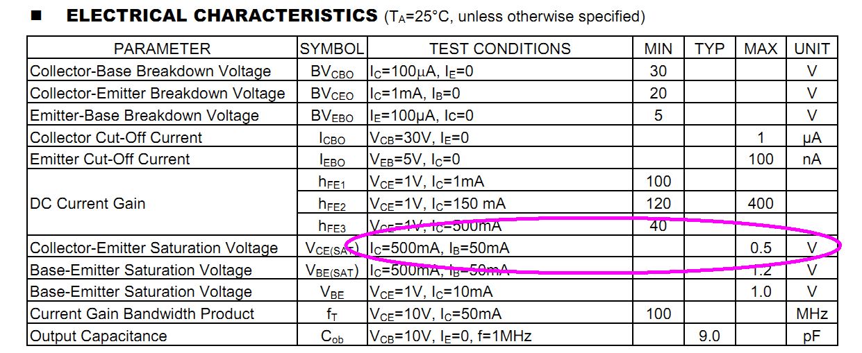
Tabelle der elektrischen Eigenschaften eines Transistors
(TA=25°C, unless otherwise specified) PARAMETER SYMBOL TEST CONDITIONS MIN TYP MAX UNIT Collector-Base Breakdown Voltage BVcbo Ic=100uA, IE=0 30 V Collector-Emitter Breakdown Voltage BVceo Ic=1mA, IB=0 20 V Emitter-Base Breakdown Voltage BVEBO IE=100uA, Ic=0 5 V Collector Cut-Off Current Icbo VCB=30V
in „Lampe mit Transistor schalten - Leuchtet nur schwach“ · Analoge Elektronik und Schaltungstechnik · · Screenshots
-
Datei
nm-ohne-f_mount.txt
0000016b B memp_memory_FRAG_PBUF_base 2000ca88 00000083 B memp_memory_TCPIP_MSG_API_base 2000cb0c 00000103 B memp_memory_PBUF_base 2000cc10 000000e3 B memp_memory_TCP_PCB_LISTEN_base 2000ccf4 000000a3 B memp_memory_REASSDATA_base 2000cd98 00000083 B memp_memory_UDP_PCB_base 2000ce1c 000000b3 B memp_memory_NETCONN_base 2000ced0 000002fb B memp_memory_TCP_PCB_base 2000d1cc 00000063 B memp_memory_SYS_TIMEOUT_base 2000d230 00000004 B netif_list 2000d234 00000004 B netif_default
in „stm32 FatFS stranges Problem“ · Mikrocontroller und Digitale Elektronik ·
-
Datei
ow.c
/////////////////////////////////////////////////////////////////////// static unsigned long time_base; static unsigned short us500; static unsigned short us420; static unsigned short us120; static unsigned short us70; static unsigned short us12; static unsigned short us2; volatile unsigned char *PORT_OW
in „Falsche TEMP mit DS1820“ · Mikrocontroller und Digitale Elektronik ·
-
PDF
15C02CH-_CD_-.pdf
Specifications Absolute Maximum Ratings at Ta=25°C Parameter Symbol Conditions Ratings Unit Collector-to-Base Voltage VCBO 20 V Collector-to-Emitter Voltage VCEO 15 V Emitter-to-Base Voltage VEBO 5 V Collector Current C 1 A Collector Current (Pulse) CP 2 A Collector Dissipation PC Mounted on a ceramic board
in „SMD-Bauteil cd 2 D4“ · Analoge Elektronik und Schaltungstechnik ·
-
PDF
2sa1216.pdf
Characteristics (Ta=25°C) External Dimensions MT-200 Symbol 2SA1216 Unit SymboI Conditions 2SA1216 Unit 36.40.3 6.00.2 VCBO –180 V VCBO VCB =–180V –100 max A 24.40.2 2.1 VCEO –180 V EBO V EB=–5V –100 max A 2-ø3.20.1 9 VEBO –5 V V(BR)CEO IC=–25mA –180 min V 7 C –17 hFE VCE =–4V, I C=–8A 30 min ±. A 1 a B VCE
in „Türstopper oder bald ein (doppel) Netzteil?“ · Analoge Elektronik und Schaltungstechnik ·
-
PDF
NSE180.pdf
B C E CENTER COLLECTOR Package 36 Maximum Ratings Parameter Symbol NSE170 NSE171 Units Collector-Base Voltage VCB 60 80 V Collector-Emitter Voltage VCEO 40 60 V Emitter-Base Voltage VEB 5 5 V Collector Current 3 A Ic 3 Power Dissipat(TA =25°C) Tj.stg 1.75 1.75 W (Tc =25°C) 10.0 10.0 W Temperature -55
in „Ersatz für NSE180“ · Analoge Elektronik und Schaltungstechnik ·
-
Datei
startup.txt
-------------------------- # copy code into internal ram # copy_section code, __code_start__, RAM_Base_Boot, __code_end__ # Relocate .data section (Copy from ROM to RAM) # copy_section data, __data_start__, __data_start__+RAM_Base_Boot, __data_end__ # --------------------------------------------- # Clear
in „Beginn der Programms nach Powerup ( nicht erst nach Reset)“ · Mikrocontroller und Digitale Elektronik ·
-
Datei
startup.txt
-------------------------- # copy code into internal ram # copy_section code, __code_start__, RAM_Base_Boot, __code_end__ # Relocate .data section (Copy from ROM to RAM) # copy_section data, __data_start__, __data_start__+RAM_Base_Boot, __data_end__ # --------------------------------------------- # Clear
in „LCP2294: Start des Programms nach Powerup“ · Mikrocontroller und Digitale Elektronik ·
-
PDF
snoaa35b.pdf
Supplies.................................................................13 List of Tables Table 1-1. Base Part Number, Channel Count, and Temperature Range....................................................................................2 Table 1-2. Maximum Input Offset Error at 25°C for Each Base Part
in „LM393 Komparatorschaltung gescheitert“ · Analoge Elektronik und Schaltungstechnik ·
-
Datei
Startup.S
Starupt Code must be linked first at Address at which it expects to run. .if (EXTMEM_MODE) .set CODE_BASE, 0x80000000 .elseif (RAM_MODE) .set CODE_BASE, 0x40000000 .else .set CODE_BASE, 0x00000000 .endif #if 0 AREA STARTUPCODE, CODE, AT CODE_BASE // READONLY, ALIGN=4 PUBLIC __startup EXTERN CODE32 (?C?INIT
in „Interrupt beim ARM“ · Mikrocontroller und Digitale Elektronik ·
-
Datei
OS_SerialTFT.h
void println(); void print(const char str[]); void print(int8_t c); void print(uint8_t b, uint8_t base = DEC); void print(int16_t n); void print(uint16_t n, uint8_t base = DEC); void print(int32_t n); void print(uint32_t n, uint8_t base = DEC); void println(const char str[]); void println(int8_t c); void println(uint8_t b, uint8_t base = DEC); void println(int16_t n); void println(uint16_t n, uint8_t base = DEC); void println(int32_t n); void println(uint32_t n, uint8_t base = DEC); void fillScreen(uint16_t color); void drawPixel(
in „Arduino Softwareserial umarbeiten auf HardwareSerial?“ · Mikrocontroller und Digitale Elektronik ·
-
Datei
OS_SerialTFT.h
void println(); void print(const char str[]); void print(int8_t c); void print(uint8_t b, uint8_t base = DEC); void print(int16_t n); void print(uint16_t n, uint8_t base = DEC); void print(int32_t n); void print(uint32_t n, uint8_t base = DEC); void println(const char str[]); void println(int8_t c); void println(uint8_t b, uint8_t base = DEC); void println(int16_t n); void println(uint16_t n, uint8_t base = DEC); void println(int32_t n); void println(uint32_t n, uint8_t base = DEC); void fillScreen(uint16_t color); void drawPixel(
in „Arduino Softwareserial umarbeiten auf HardwareSerial?“ · Mikrocontroller und Digitale Elektronik ·
-
Datei
PinKlasse_klassisch_toggle.ino.elf.txt
ldi r29, 0x3F ; 63 ac: de bf out 0x3e, r29 ; 62 000000ae <__do_copy_data>: ae: 18 e2 ldi r17, 0x28 ; 40 b0: a0 e0 ldi r26, 0x00 ; 0 b2: b8 e2 ldi r27, 0x28 ; 40 b4: e6 e2 ldi r30, 0x26 ; 38 b6: f4 e0 ldi r31, 0x04 ; 4 b8: 02 c0 rjmp .+4 ; 0xbe <__do_copy_data+0x10> ba: 05 90 lpm r0, Z+ bc: 0d 92 st X+,
in „Buchempfehlung C++ und MCUs“ · Mikrocontroller und Digitale Elektronik ·
-
Datei
t6963c_main_v3.asm
unterdrücken .INCLUDE <m88def.inc> ; Controllertyp .equ F_CPU = 7372800 ; Systemtakt in Hz .equ TXT_BASE = 0x0000 .equ GFX_BASE = 0x0300 .equ FONT_SIZE = 6 ; änderbar über FS-Pin am Display .equ LCDMode = 0b10000000 .equ SPALTEN = 128/FONT_SIZE .equ GFX_ZEILEN = 64 .equ TXT_ZEILEN = 64/8 ;=============
in „Optimierung ASM-Code für GLCD“ · Mikrocontroller und Digitale Elektronik ·
-
PDF
ca3140-a.pdf
S 1M 48 48 V (See Figure 27) Equivalent Input Noise Voltage (See Figure 35) eN RS= 100 f = 1kHz 40 40 nV/Hz f = 10kHz 12 12 nV/Hz Short Circuit Current to Opposite Supply IOM + Source 40 40 mA OM - Sink 18 18 mA Gain-Bandwidth Product, (See Figures 6, 30) T 4.5 4.5 MHz Slew Rate, (See Figure 31)
in „OpAmp Ausgang schwingt mit 50Hz (oder 100)“ · Analoge Elektronik und Schaltungstechnik ·
-
Datei
main.c
Input P1MDIN = 0xBF; // P1.6 analog input Poti P1MDOUT = 0x08; // "Taster" zum Signalisieren für BaseInfo. P2MDOUT = 0x99; // P2.0 LED, P2.3 Reset_n, P2.7 WakeUp, P2.4 Blaue LED P1SKIP = 0x40; // Poti auf der Crossbar überspringen. SPI0CFG &= ~0x30; // SPI SPI0CFG |= 0x10; // CPHA = 1; CPOL = 0 SPI0CN
in „Puffer-Problem mit C8051F320 (8051)“ · Mikrocontroller und Digitale Elektronik ·
-
PDF
grasshopper_schematic.pdf
[1] PA19 38 37 [1] PA16 N3 PA16(USART1-CLK/TIMER0-B1) PC16(MACB0-RX_MDC) B15 ETH_MDC [4] [1] PA20 40 39 [1,5] USART1_RXD N1 PA17(USART1-RXD/TIMER0-B2) PC17(MACB0-MDIO) D10 ETH_MDIO [4] [1,4] CLK25 42 41 [1,5] USART1_TXD P2 PA18(USART1-TXD/TIMER0-CLK2) PC18(MACB0-SPEED/AUX2-MOD5) B10 [1,6] PWRLED 44
in „Grasshopper Inbetriebnahme“ · Mikrocontroller und Digitale Elektronik ·
-
Datei
strace.txt
(4, {msg_name={sa_family=AF_NETLINK, nl_pid=0, nl_groups=00000000}, msg_namelen=12, msg_iov=[{iov_base=[{{len=76, type=0x14 /* NLMSG_??? */, flags=NLM_F_MULTI, seq=1555679995, pid=406}, "\2\10\200\376\1\0\0\0\10\0\1\0\177\0\0\1\10\0\2\0\177\0\0\1\7\0\3\0lo\0\0"...}, {{len=0, type=0x8 /* NLMSG_??? */,
-
PDF
an920-d.pdf
since it will reduce the power dissipation of the output switch considerably. This L + C o RL μA78S40 feature maybedisabledontheμA78S40 only, by connecting a small signal PNP transistor as a clamp. The emitter is connected to C , the base to the reference output, and the c. Voltage−Inverting |V | V T
in „MC34063 als Step Up arbeitet nicht“ · Analoge Elektronik und Schaltungstechnik ·
-
PDF
AN920-D_MC34063_Theory_and_Applications_.pdf
a feature since it will reduce the L power dissipation of the output switch considerably. This A78S40 + Co RL feature maybedisabledonthe A78S40 only, by connecting a small signal PNP transistor as a clamp. The emitter is connected to C T the base to the reference output, and the c. Voltage–Inverting
in „Schaltregler MC34063 - Wie berechnet man CT?!“ · Analoge Elektronik und Schaltungstechnik ·
-
PDF
AN920-D.PDF
a feature since it will reduce the L power dissipation of the output switch considerably. This A78S40 + Co RL feature maybedisabledonthe A78S40 only, by connecting a small signal PNP transistor as a clamp. The emitter is connected to C T the base to the reference output, and the c. Voltage–Inverting
in „Frage zu Schaltregler“ · Analoge Elektronik und Schaltungstechnik ·
-
PDF
MC34063_AN920-D.PDF
a feature since it will reduce the L power dissipation of the output switch considerably. This A78S40 + Co RL feature maybedisabledonthe A78S40 only, by connecting a small signal PNP transistor as a clamp. The emitter is connected to C T the base to the reference output, and the c. Voltage–Inverting
in „Spule für Schaltnetzteil“ · Mikrocontroller und Digitale Elektronik ·
-
PDF
AN920-D.pdf
since it will reduce the power dissipation of the output switch considerably. This L + C o RL μA78S40 feature maybedisabledontheμA78S40 only, by connecting a small signal PNP transistor as a clamp. The emitter is connected to C , the base to the reference output, and the c. Voltage−Inverting |V | V T
in „Spannungsregelung mit Step-Up/Down Regler“ · Analoge Elektronik und Schaltungstechnik ·
-
PDF
AN920-D_MC34063_Theory_and_Applications_.pdf
a feature since it will reduce the L power dissipation of the output switch considerably. This A78S40 + Co RL feature maybedisabledonthe A78S40 only, by connecting a small signal PNP transistor as a clamp. The emitter is connected to C T the base to the reference output, and the c. Voltage–Inverting
in „MC34063 Strombegrenzung“ · Mikrocontroller und Digitale Elektronik ·
-
PDF
AN920-D.PDF
since it will reduce the power dissipation of the output switch considerably. This L + C o RL μA78S40 feature maybedisabledontheμA78S40 only, by connecting a small signal PNP transistor as a clamp. The emitter is connected to C , the base to the reference output, and the c. Voltage−Inverting |V | V T
in „Suche Buck-Boost für LiIon-Spannung auf 3,3V“ · Analoge Elektronik und Schaltungstechnik ·
-
PDF
MN-RBXEB-01.pdf
interrupt controller test next. The DMA page register test passed. Performing the 60h DMA Controller 1 base register test next. The DMA controller 1 base register test passed. 62h Performing the DMA controller 2 base register test next. 65h The DMA controller 2 base register test passed. Programming DMA controllers
-
PDF
ssd1623.pdf
Phase5_en 01 02 03 Clock Overall timing scaling Osc_En E_CLK_DIV[2] E_CLK_DIV[1] E_CLK_DIV[0] CLK_Base[3] CLK_Base[2] CLK_Base[1] CLK_Base[0] 04 05 06 07 08 Reset Reset SW_Reset[1] SW_Reset[0] lock1 lock0 09 DC/DC 2 Booster voltage DC_Volt[4] DC_Volt[3] DC_Volt[2] DC_Volt[1] DC_Volt[0] DOFF_out[1] DOFF_out
in „E-Ink Display im Blutzuckermeßgerät“ · Mikrocontroller und Digitale Elektronik ·
-
PDF
bfr183.pdf
Symbol Value Unit 12 V Collector-emitter voltage VCEO Collector-emitter voltage VCES 20 Collector-base voltage VCBO 20 2 Emitter-base voltage VEBO Collector current I 65 mA C Base current IB 5 2) Total power dissipation Ptot 450 mW T ≤ 60 °C S Junction temperature Tj 150 °C Ambient temperature TA -65
in „Induktivität SOT23“ · Analoge Elektronik und Schaltungstechnik ·
-
PDF
activity_recognition_from_accelerometer_data.pdf
for different activities Correlation is calculated between each pair of axes as the than that of base-level classifiers, base-level-classifiers are ratio of the covariance and the product of the standard devia- known to outperform meta-level-classifiers on several data tions uorr)xGy* ¿ uτ xxyy*. Correlation
in „Menschliche Bewegung detektieren (laufen von gehen unterscheiden)“ · Mikrocontroller und Digitale Elektronik ·
-
PDF
Preisliste_deutsch_0509_2.pdf
1024x768 Pixel XGA, CPU mit Intel-Prozessor Celeron M 1,5 GHz, Arbeitsspeicher 1 GB RAM, Festplatte 40 GB, 2 x PS/2-Anschluß, 1 x Audio, 4 x USB 2.0 (2x frontseitig),2 x RS232, 1 x Ethernet 10/100/1000 Base-T, 2 x Steckplätze PCI (mit opt. LW nur 1 nutzbar), Software: Windows XP Prof. MUI JI-PC515 10000688
in „Siemens Logo“ · Haus & Smart Home ·
-
Datei
DG24128.asm
--------------------- .equ F_CPU = 8000000 .equ CYCLES_PER_US = ((F_CPU+500000)/1000000) .equ TXT_BASE = $0000 .equ GFX_BASE = $0200 .equ SPALTEN = 240/8 .equ GFX_ZEILEN = 128 .equ TXT_ZEILEN = 128/8 ; 0bxxxxxyyyyyyyyzzz ; x - CHR_OFFSET ; y - CHR_CODE ; z = CHR_LINE .equ CHR_OFFSET = 3 .equ CHR_CODE
-
PDF
spma014.pdf
space than is needed. Changing the locals to int/unsigned (or long and unsigned long) often saves 40% or more in code space. SeeTable 3 for a comparison. Table 3. Comparison of Variable Sizes Locals of size int Locals of size short int (half word) typedef int BASE; typedef short BASE; BASE foo(BASE last, BASE x, BASE y) BASE foo(BASE last, BASE x, BASE y) { { 0: 2300 movs r3, #0 0: f04f 0c00 mov.w ip, #0; 0x0 2: e002 b.n a <foo+0xa> 4: e004 b.n 10 <foo+0x10> BASE i; BASE i; for (i = 0; i < last; i++) for
in „ARM Cortex & GCC: Worauf achten für "optimalen" Code?“ · Mikrocontroller und Digitale Elektronik ·
-
PDF
AN1040-D.PDF
enclose components and quite dependent upon the surface finishes. using grease. The newer synthetic base greases show far For several years, thermal joint compounds, often called less tendency to migrate or creep than those made with a grease, have been used in the interface. They have a silicone oil base
in „Welches Transistorgehäuse ist am besten zu kühlen?“ · Mikrocontroller und Digitale Elektronik ·
-
PDF
AN1040-D.PDF
enclose components and quite dependent upon the surface finishes. using grease. The newer synthetic base greases show far For several years, thermal joint compounds, often called less tendency to migrate or creep than those made with a grease, have been used in the interface. They have a silicone oil base
in „Wärmewiderstand Rthg - Rthgk“ · Analoge Elektronik und Schaltungstechnik ·
-
PDF
AN1040-D.PDF
enclose components and quite dependent upon the surface finishes. using grease. The newer synthetic base greases show far For several years, thermal joint compounds, often called less tendency to migrate or creep than those made with a grease, have been used in the interface. They have a silicone oil base
in „Gibt es Alternativen zu Silikonpads?“ · Mikrocontroller und Digitale Elektronik ·
-
PDF
AN1040-D.pdf
enclose components and quite dependent upon the surface finishes. using grease. The newer synthetic base greases show far For several years, thermal joint compounds, often called less tendency to migrate or creep than those made with a grease, have been used in the interface. They have a silicone oil base
in „Kurzschluss durch Kühlörper?“ · Analoge Elektronik und Schaltungstechnik ·
-
PDF
AN1040-D.PDF
enclose components and quite dependent upon the surface finishes. using grease. The newer synthetic base greases show far For several years, thermal joint compounds, often called less tendency to migrate or creep than those made with a grease, have been used in the interface. They have a silicone oil base
in „Reicht das Eloxal als Isolierung?“ · Mechanik, Gehäuse, Werkzeug ·
-
PDF
AN1040-D.pdf
enclose components and quite dependent upon the surface finishes. using grease. The newer synthetic base greases show far For several years, thermal joint compounds, often called less tendency to migrate or creep than those made with a grease, have been used in the interface. They have a silicone oil base
in „MOSFET Power Dissipation“ · Analoge Elektronik und Schaltungstechnik ·
-
Datei
Lauritzen_Verilog.txt
real kv = 1; // Turn-on Voltage fitting parameter (nu) parameter real T0 = 1.0e-6 from(0:inf); // Base transit time at low Voltagee (s) parameter real tB = 2.0e-6 from(0:inf); // Base carrier lifetime (s) parameter real tA = 160.0e-9 from(0:inf); // equivalent lifetime of anode emitter efficiency (s)
in „LTSpice - grammatical error bei .FUNC“ · Mikrocontroller und Digitale Elektronik ·
-
Datei
mit_kontrollausgabe.asm
print((unsigned long) b, base); } size_t Print::print(int n, int base) { return print((long) n, base); 380: 6c 01 movw r12, r24 382: 99 0f add r25, r25 384: ee 08 sbc r14, r14 386: ff 08 sbc r15, r15 size_t Print::print(long n, int base) { if (base == 0) { return write(n); } else if (base == 10) { if (n < 0) { 388: f7 fe sbrs r15, 7 38a: 23 c0 rjmp .+70 ; 0x3d2 <Print::println(int, int) [clone .constprop.3]+0x5e> return write(str);
in „AVR Inline Optimierung kaputt?“ · Mikrocontroller und Digitale Elektronik ·
-
PDF
an762.pdf
recommended. The center tap of T2 is actually bc (Figure 1), but for where L = Inductance in H R = Base-to-Base or Collector-to-Collector stabilization purposes, b and c are separated by RF chokes Impedance by-passed individually by C8 and C9. f = Lowest Frequency in MHz For example, in the 180 Watt version
in „Stackpole Ferrit Kerne für RF Verstärker“ · HF, Funk und Felder ·
-
Datei
t6963c_main_v2.asm
unterdrücken .INCLUDE <m88def.inc> ; Controllertyp .equ F_CPU = 7372800 ; Systemtakt in Hz .equ TXT_BASE = 0x0000 .equ GFX_BASE = 0x0300 .equ FONT_SIZE = 6 ; änderbar über FS-Pin am Display .equ LCDMode = 0b10000000 .equ SPALTEN = 128/FONT_SIZE .equ GFX_ZEILEN = 64 .equ TXT_ZEILEN = 64/8 ;=============
in „Optimierung ASM-Code für GLCD“ · Mikrocontroller und Digitale Elektronik ·
-
 Bild
Bild
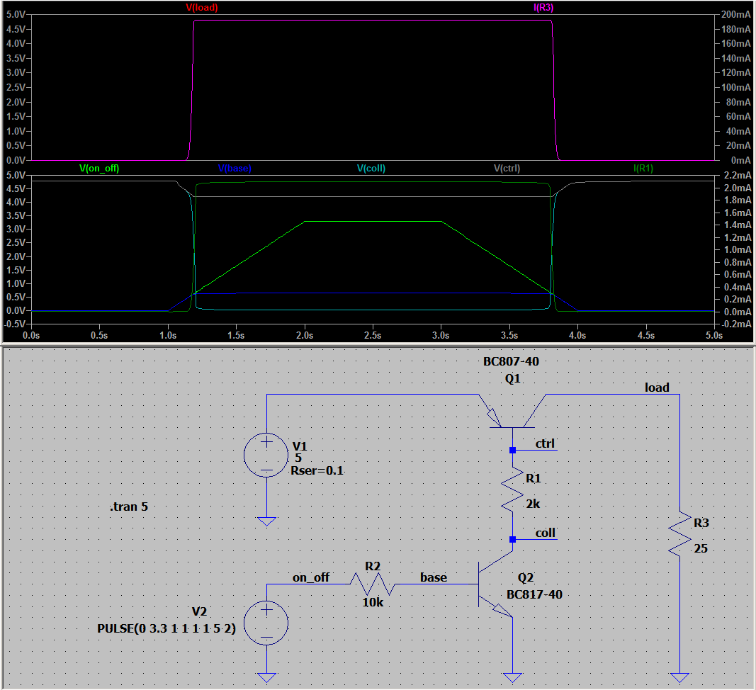
Schaltplan und Simulationsergebnisse einer Transistorschaltung
V(load) I(R3) 200mA 180mA 160mA 140mA 120mA 100mA 80mA 60mA 40mA 20mA 0mA 5.0V 4.5V 4.0V 3.5V 3.0V 2.5V 2.0V 1.5V 1.0V 0.5V 0.0V V(on_off) V(base) V(coll) V(ctrl) I(R1) 2.2mA 2.0mA 1.8mA 1.6mA 1.4mA 1.2mA 1.0mA 0.8mA 0.6mA 0.4mA 0.2mA 0.0mA -0.2mA 5.0V 4.5V 4.0V
in „ESP32 3.3V Logik Level Mosfet“ · Analoge Elektronik und Schaltungstechnik · · Screenshots
-
Datei
AT91SAM7S64.h
0xFFFFF200) // (DBGU) Base Address #define AT91C_BASE_PIOA (AT91_CAST(AT91PS_PIO) 0xFFFFF400) // (PIOA) Base Address #define AT91C_BASE_CKGR (AT91_CAST(AT91PS_CKGR) 0xFFFFFC20) // (CKGR) Base Address #define AT91C_BASE_PMC (AT91
in „AT91SAM7S64 Compiler Fehlermeldung“ · Mikrocontroller und Digitale Elektronik ·
-
Datei
mc9s12ne64.h
EPHY Module Stops While in Wait */ byte LEDEN :1; /* LED Drive Enable */ byte DIS10 :1; /* Disable 10BaseT PLL */ byte DIS100 :1; /* Disable 100 Base-TX PLL */ byte ANDIS :1; /* Auto Negotiation Disable */ byte EPHYEN :1; /* EPHY Enable */ } Bits; } EPHYCTL0STR; extern volatile EPHYCTL0STR _EPHYCTL0 @(REG_BASE
in „Hilfe MC9S12NE64 interrupt programmierung“ · Mikrocontroller und Digitale Elektronik ·