-
Thread
Flex-Leitung für Renesas Debugger
lieferbar: https://www.mouser.de/ProductDetail/Renesas-Electronics/M3T-F160-EXTC?qs=Znm5pLBrcAKfFb8l2vRIKA%3D%3D
lieferbar: > https://www.mouser.de/ProductDetail/Renesas-Electronics/M3T-F160-EXTC?qs=Znm5pLBrcAKfFb8l2vRIKA%3D%3D Danke für die Bemühungen. Es ist nur leider nicht das Ersatzteil, welches wir benötigen. Gruß Uhmel
-
Thread
Hameg HM-605 X-Achse nur Halb zu sehen
Giuseppe L. schrieb im Beitrag #7641976: > Hab noch was kurioses gefunden. Zwei Widerstände parallel zusammen > gelötet. > Der eine hat 10K der zweite 6,91K demnach zusammen 4,086K. > Laut Plan vom HM-605
an Seite zum C3109 L/R +6,54V/-0,21V > > -T3109 Basis (Verbindung R3136-R3135) > L/R +6,6V/-0,2V > > -VR3103 links > an Seite links zum VR3103 L/R +6,8V/+0,43V an Seite Rechts Platinenrand L/R +6,8V/+0,44V
-
 Bild
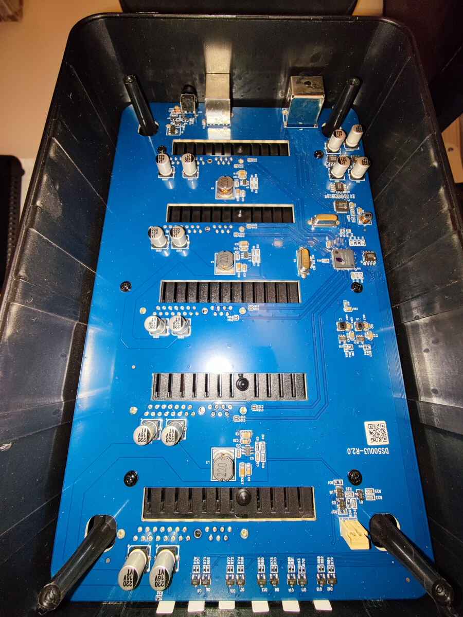
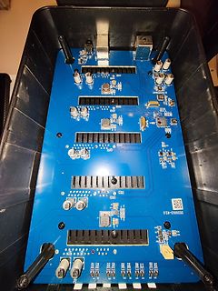
Blaue Leiterplatte in schwarzem Gehäuse
DS500U3-R2.0 220 16V 220 16V 220 16V 220 16V L1 L2 L3 L4 L5 L6 L7 L8 L9 L10 L11 L12 L13 L14 L15 L16 L17 L18 L19 L20 L21 L22 L23 L24 L25 L26 L27 L28 L29 L30 L31 L32 L33 L34 L35 L36 L37 L38 L39 L40 L41 L42 L43 L44 L45 L46 L47 L48 L49 L50 L51 L52 L53 L54 L55 L56 L57 L58 L59 L60 L61 L62 L63 L64 L65 L66 L67 L68 L69 L70 L71 L72 L73 L74 L75 L76 L77 L78 L79 L80 L81 L82 L83 L84 L85 L86 L87 L88 L89 L90 L91 L92 L93 L94 L95 L96 L97 L98 L99 L100 L101 L102 L103
-
Thread
Kennt oder besitzt jemand dieses Philips Netzteil PE1540 DC
Drehpotis "grob" und "fein" werden mit 6,5Volt gespeist, die Strom- und Volt-Potis haben je ihre eigene BZX91. Die sind im gelben Gehäuse schwarz im Klartext beschriftet:BZX91. An den Potis lässt sich aussen herum 6,5 Volt messen, an jedem Schleifer null bis 6Volt abgreifen (mittlerer Anschluss gegen Plus-Ausgangsbuchse
angeschlossener "aufzuladender Autobatterie" Ich hatte zum Laden von Motorradbatterien eine Schaltung mit L200 plus Transistor aufgebaut, umschaltbar 7,05 / 14,1 Volt. Nachdem die mal wieder verreckt war, habe ich die Elektronik in den Müll verfrachtet, Gehäuse, Trafo, Kühlkörper und Meßwerk natürlich nicht
-
Thread
140 Ah Blei-Gel Batterie am sterben?
Florian L. schrieb im Beitrag #7635373: > Schlagartiger Drop um 2 Volt sieht nach Zellschluss aus. ACK, und damit RIP.
Stunden damit betreiben können. ;O) Mit freundlichem Gruß: Bernd Wiebus alias dl1eic http://www.l02.de
-
Thread
Notstromsystem in einem Entwicklungsland
Sebastian L. schrieb im Beitrag #7634382: > Ich hoffe es geht um eine 400/230V Drehstromnetz. Bei einphasiger > Versorgung wird das Leben schwieriger. Klar, mit einphasig kommt ja heute niemand mehr klar.
schnell an der Überspannung eingehen: https://www.falstad.com/circuit/circuitjs.html?ctz=CQAgjCAMB0l3BWcMBMcUHYMGZIA4UA2ATmIxAUgpABZsKBTAWjDACgBnEFFG8MFCFx9WgqlQBmAQwA2HBmxnde-QaNVQosCDARgMxHjTwIE2LAhxQ2AJ1rHwGQhQGPnVMPDYA3DevUoCO7gtFQouJri0AhsACpCkCKu2HgiTpp8MBBMMDT6eNiGhNg0xAJguPQ50J5wBTxoNIQIdAhi0KTEbADuCWnOwtxB1r0Bw4OB7j19GoN44tNzVCl88yNCqSBrKxqQi4lDzjQOk9ZcemrpF4eRINJyCr3HeDfXp3u9O-pHDt-WAPYhQiZUKkIRocDQYJqIRsQGCYEZSBg7AQ3IhQSCbBsFIhABiOi0kAgYG0IBYIAAkgA7AAmAFcAMYAFyk1MZCiAA
-
Thread
Drehzahlregelung eines 3 stufigen 230 Volt Lüftermotors
elektronischer-Spannungs-Regler-Gouverneur-Thermostat-Drehzahlregler/dp/B01LXLU3SD/ref=sr_1_9?__mk_de_DE=%C3%85M%C3%85%C5%BD%C3%95%C3%91&crid=24HK76PGMA491&dib=eyJ2IjoiMSJ9.BzI1AJ1ANc5HWrTzrR1fHf-hJkZU27vk3_axjEw5S33P7TA-5E2VaT8X3XrsF6lQEDyo6xVy9_7Y7i_aisLey3TgcCwN9671gHxomiroGeSv6AMtq19QU-Uf7v3NBnWSDRF14328VYVX0eqQTcQOsk3Kg39AekW4BYsLbB-cVDFGVWoYYFNyy38OXCdwqrwJODwUuZP39JNB7X-g8fn_U7KOlbTVdFz0G_fuFXnKI7kXlmBe0G1WdBo1OAvyf7yZDpb
-
Thread
8mm Welle verlängern am DC Motor
Walfront-Kupplungskoppler-Aluminiumlegierungs-Verbindungswelle-Schrittmotor/dp/B07BN95VCX/ref=sr_1_11?__mk_de_DE=%C3%85M%C3%85%C5%BD%C3%95%C3%91&crid=1AE0CHFC1DYQW&dib=eyJ2IjoiMSJ9.YnMjSyTUFv1GBsMLGsVK4YwrWyUTBbY-Fxu4lk8-k3z34PzeCPZ4crljWbUA9tHx6G6cMUiGzM_DsE-Uo4MiGotkbeKB80ouL00zyDUQ50H0UEL4_RWV8Hh148NwAxlyFnYLs4zSCNPWUaWBdwwe3mceYN9_b02GQ2ZoVJ6XohKDv0Ro5BrVMWelB_-YRdqffxhL7qfRE9d8Z1ep-pjTQNHbYtwQluhNuBFh_rUaEg9En3yrCw0toxB0_xo3_tnx4ZbaPfarZX3MGcPlH5e0aCCdjHtKhIPrbrp5ZiqtWTI._V5iZuWD8r7J6Cp_pV5w11hq6707qybTG-n55fhd3kI&dib_tag=se&keywords=%228mm%22%2Bwelle%2Bkupplung&qid
-
 Bild
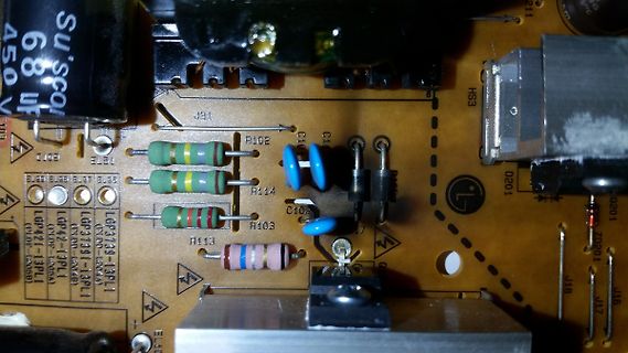
Nahaufnahme einer Leiterplatte mit elektronischen Bauteilen
68 uF 450 V J91 R102 C1 R114 P114 C102 R103 R113 HS3 D201 L G201 Q201 J18 J17 LGP421-13PL1 LGP3739-13PL1 LGP421-13PL1 LGP3739-13PL1
-
Thread
Kellerbeleuchtung mit 12V Motorradbatterie
BSA-Motorradbatterie-Lebensdauer-auslaufsicher-wartungsfrei/dp/B0CXTQC573/ref=sr_1_17?__mk_de_DE=%C3%85M%C3%85%C5%BD%C3%95%C3%91&crid=11G99X3RBCL8Z&dib=eyJ2IjoiMSJ9.bvP5lobF4MK7TeWxPXPiD4BvkPSb_6R4B9Nu9nKAFxih2VHl0Ftf24jweeVKSiOegHmmlGJLx9fLotEAdDA_QaVerIUuw62GifiGfWWCdFKfZszYsiQ2reUYvpD4tg0_p8PQJuOZ4-ZJjww9QAfIQ6wCSnCwWnnh1sWHqC2D4vwyAKZNgVOhKjtyYdpGiLyPZYYPy6pBoPCVWj254UAq3pCDILqj70dkr5YBtR2tm5Vxfs_K4goS0qbuJak2nzLgTCR9By4W7HU54BpX38eDGbVJy9kEBDg2bmHU5ApkqUg.DeI6rtsbfpf0LgrlsY12jYueAoauvi8amvmyAFhgBqQ
Buzz L. schrieb im Beitrag #7626688: > zwei 12V Led-Leisten [1] installieren. Also zwei mal 1600 Lumen. Buzz L. schrieb im Beitrag #7626871: > Also es geht um ein kleines Kellerabteil Uiuiui, das
-
Thread
PAM8403 im gleichen Stromkreis wie ESP und VS1053, Rauschen
eyJ2IjoiMSJ9.1FGZkVh9mjQ2xgJ-LJasZeADGPExqnm-CraoIp9YwUZpYgKDTEXjhbxEwRgvRv5nRfEeovNWg1j_NDhc24T0ftXUfXFunnjbfQnNMJUlsb8P91xfJerXlTMtfazZTLgvH5YSXMcvKoYpvFtQNMOoDyRLtDJtKAYufQBbYBVva321cvbjBY044trsgCraScXYON9b39U5LjQCsBK0ML0naSpN3GxMVOcz9hTbDczaC4M.U0e4n9fQSQSrerhNP9xIXN3fi6GsRxnAVv6BtLVRiM4&dib_tag=se&keywords=ic+tda2822m
Problem ist: Der Codec hat einen Kopfhörer-Ausgang, der eigentlich auch für nix anderes taugt. L und R Signale beziehen sich auf "GBUF", nicht auf GND. Beste Lösung: Nimm den digitalen I²S-Ausgang vom Codec-Chip, und leite ihn zu einem Verstärker mit I²S-Eingang. Keine Analoge Übertragungsstrecke
-
 Bild
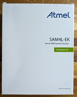
Verpackung eines Atmel SAM4L-EK Evaluation Kits
Atmel SAM4L-EK Atmel ARM-based Solution Evaluation Kit P/N# AT91SAM4L-EK
-
 Bild
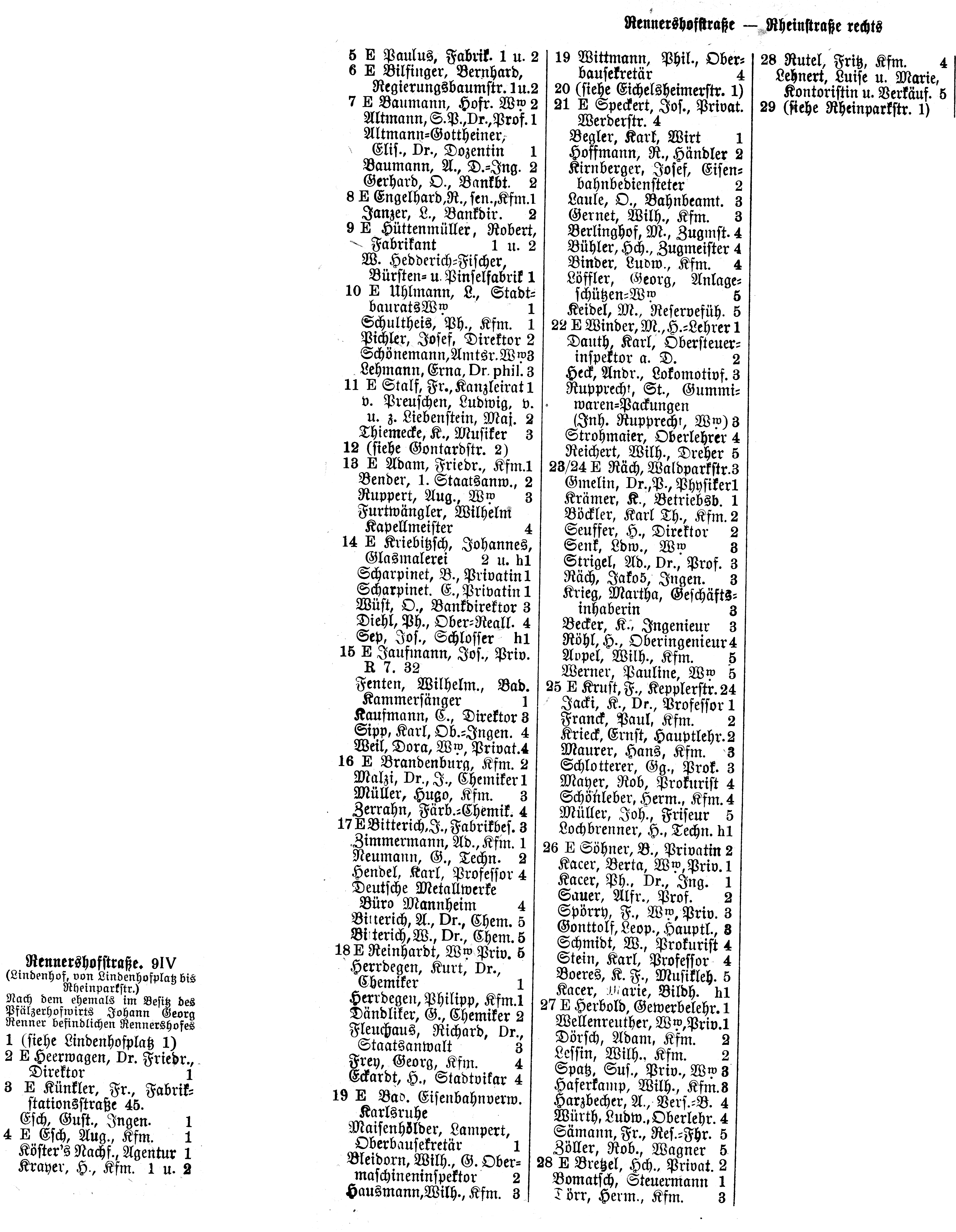
Alte Telefonbuchseite mit Namen und Adressen
Neuerdingsstraße 91V 5 E Paulus, Pabst, 1 u 2 6 E Bingert, Bernhard, Regierungsbaumeistr, 1 u 2 7 E Baumann, Hofw. 2 W Altmann, S. Dr., Prof. 1 Baumann, A., Dr., Ing. 2 Ekliff, Dr., Ingenieur 1 Engethard, R., Telekom. Janzer, L., Bankdir. 2 Eutermaier, Robert, 9 E Bürmaster, R., Ing. 2 Berlin, W., Zugst. 4 Bülker, Otto, Ingenieur 4 Binder, Ludwig, Kfm. 1 Börner, Walter, 2 W Schultis, PK., Kfm. 1 Schönemann, Anton, W. Lehmann
-
Thread
-
 Bild
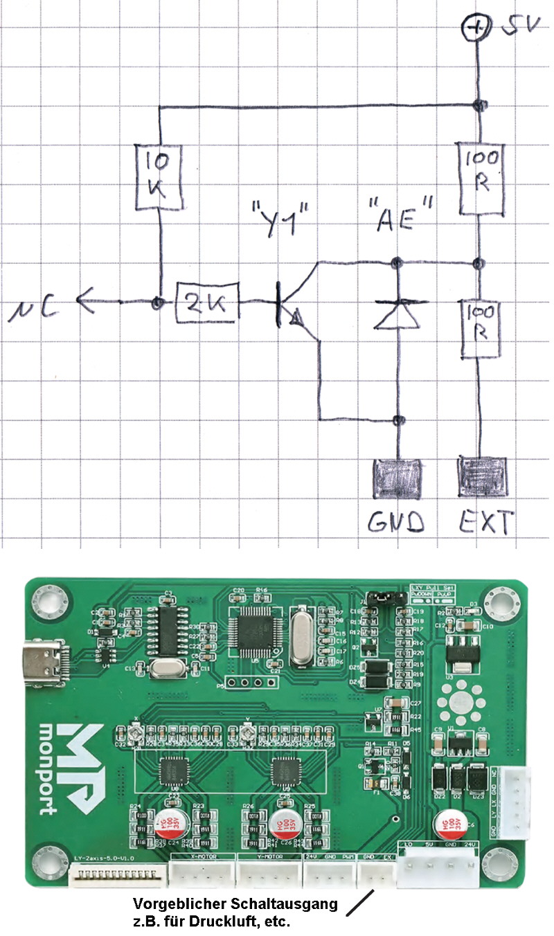
Handgezeichneter Schaltplan und Foto einer Leiterplatte
SV 10K "Y1" "AE" 100 R 2K NC 100 R GND EXT monport Y-Motor X-Motor L1 L2 L3 L4 L5 L6 L7 L8 L9 L10 L11 L12 L13 L14 L15 L16 L17 L18 L19 L20 L21 L22 L23 L24 L25 L26 L27 L28 L29 L30 L31 L32 L33 L34 L35 L36 L37 L38 L39 L40 L41 L42 L43 L44 L45 L46 L47 L48 L49 L50 L51 L52 L53 L54 L55 L56 L57 L58 L59 L60 L61 L62 L63 L64 L65 L66 L67 L68 L69 L70 L71 L72 L73 L74 L75 L76 L77 L78 L79 L80 L81 L82 L83 L84 L85 L86 L87 L88 L89 L90 L91 L92 L93 L94 L95 L96 L97 L98 L99 L100 L101 L102 L103
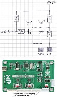
-
 Bild
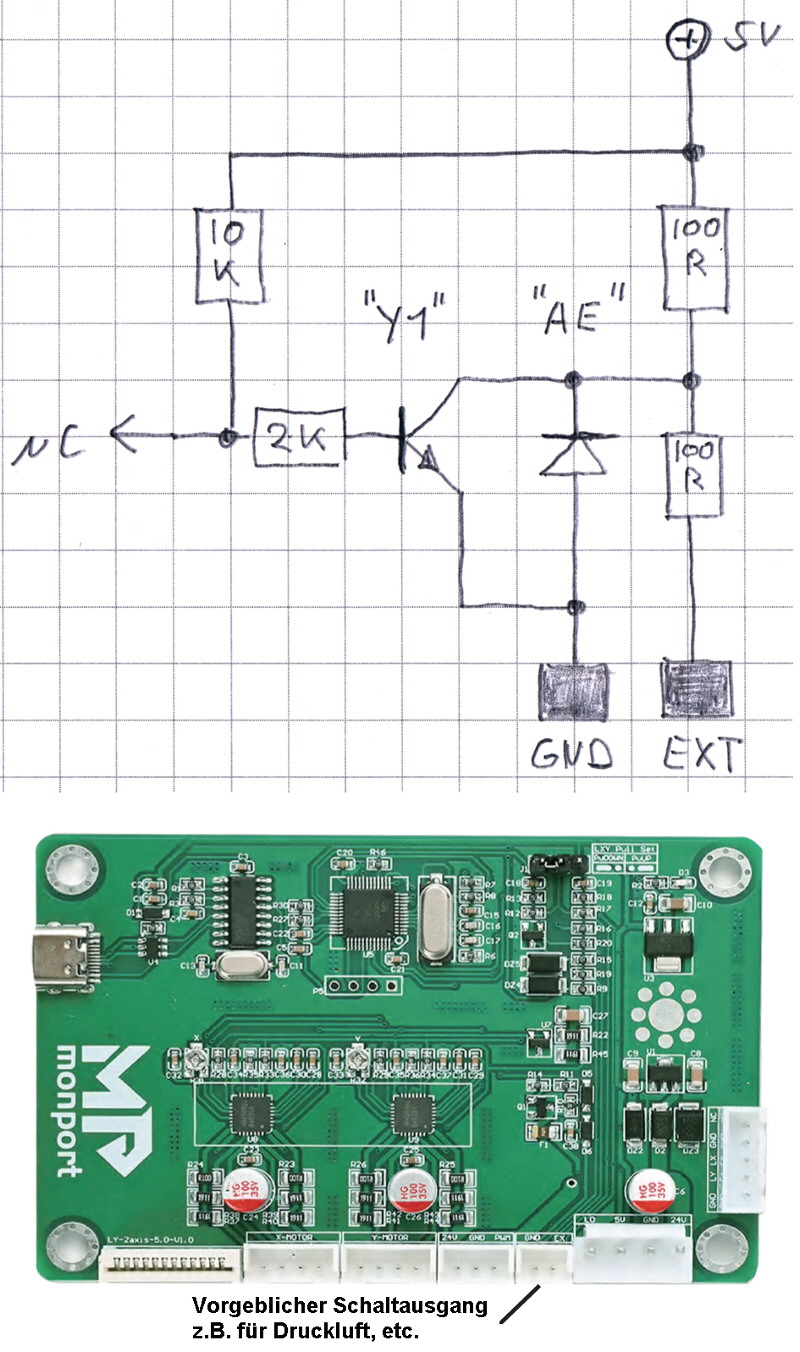
Handgezeichneter Schaltplan und Foto einer Leiterplatte
SV 10K Y1 AE 100R 2K NC 100R GND EXT monport Y-Motor X-Motor L1 L2 L3 L4 L5 L6 L7 L8 L9 L10 L11 L12 L13 L14 L15 L16 L17 L18 L19 L20 L21 L22 L23 L24 L25 L26 L27 L28 L29 L30 L31 L32 L33 L34 L35 L36 L37 L38 L39 L40 L41 L42 L43 L44 L45 L46 L47 L48 L49 L50 L51 L52 L53 L54 L55 L56 L57 L58 L59 L60 L61 L62 L63 L64 L65 L66 L67 L68 L69 L70 L71 L72 L73 L74 L75 L76 L77 L78 L79 L80 L81 L82 L83 L84 L85 L86 L87 L88 L89 L90 L91 L92 L93 L94 L95 L96 L97 L98 L99 L100 L101 L102 L103
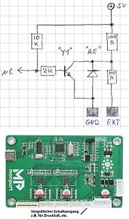
-
Thread
Tektronix TDS744A Netzteil
158V oder 408 - 220 = 188V arbeiten. Im Anhang eine LTspice-Simulation, ein schneller Hack, die L-Werte stimmen überhaupt nicht, aber das Ding schwingt und bringt eine geregelte Ausgangsspannung (hier 18V). L1 ist eine sättigbare Induktivität (saturable inductor). L2-L4 sind der Trafo T3. R1 ist
J300A und J300B, sind die Bauteile (U375 und Umgebung) bestückt? Wieviel Ohm hat R265 (51, 81 oder 91)? Wenn die Helligkeit insgesamt zu hoch ist, mit screen (R80 A30/3 screen (grid2)) dunkler stellen. Stimmen die +75 und -75V? In den Service-PDF (z.B. TEKTRONIX_TDS_620A_640A_644A_SM.PDF, 110
-
 Bild
Nahaufnahme einer grünen Leiterplatte mit elektronischen Bauteilen
Ele, C44, U4, L3, DL6, C29, R115, C45, U6, C41, DL5, R118, R117, R90, Q31, D3, R88, C34, R91, R87, D6, D5, R60, R57, Q32, C33, J2, ED, J3, ED, R25, R28, R20, R19, R16, C12, R15, R24
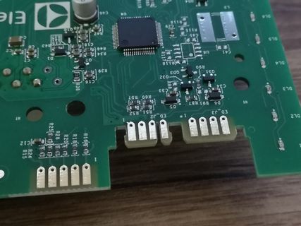
-
 Bild
Nahaufnahme einer Leiterplatte mit integriertem Schaltkreis
R1 Q3 1AM R58 R42 R44 R56 R57 HDMI IN U11 R91 J2 R92 R93 R18 R190 C180 JP3 C48 C47 ZB32L003F8 P3Q091B 2335A
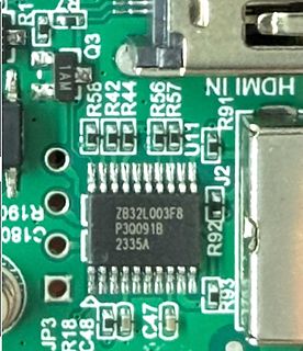
-
 Bild
Nahaufnahme einer Leiterplatte mit integriertem Schaltkreis
R1 Q3 1AM R58 R42 R44 R56 R57 HDMI IN U11 R91 J2 R92 R93 R18 R190 C180 JP3 C48 C47 ZB32L003F8 P3Q091B 2335A
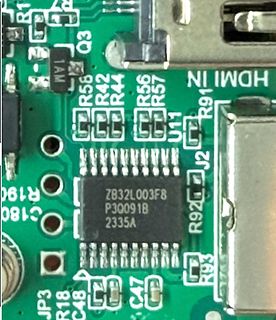
-
 Bild
Warenkorb-Abrechnung eines Online-Shops
Entwicklungsunterstützung Unterstütze deine Entwicklungsanwendung mit einem Einmalbeitrag 3x Beautiful Boards HD 4L + Stellar Stencil 67,99 € Entwicklungsunterstützung 1,68 € Versand 0,00 € Netto 69,67 € Steuer 19 % 13,24 € Gesamt 82,91 € Geschätzter Versand Freitag, 8. März 2024

-
Thread
NodeMCU ESP8266 PWM-Signal Motor
:04:58.977 -> csum 0x2b 18:04:58.977 -> v00044080 18:04:58.977 -> ~ld 18:04:59.010 -> ��n�r��n|�l�l`bbrl�nb�nl`�rl�l�� [/code] Hat jemand eine Idee, was falsch ist und bin ich hier auf dem richtigen Weg ? Danke...
, 52, 54, 57, 59, 62, 65, 68, 70, 73, 76, 79, 82, 85, 88, 91, 94, 97, 100, 103, 106, 109, 112, 116, 119, 122, 125, 128, 131, 134, 138, 141, 144, 147, 150, 153, 156, 159, 162, 165, 168, 171, 174, 177, 180, 183
-
Thread
5V Stabilisieren für CO2 sensor
A4rtsstromversorgungsmodul-4-75V-12V/dp/B07PPKR4HW/ref=sr_1_8?__mk_de_DE=%C3%85M%C3%85%C5%BD%C3%95%C3%91
Matt L. schrieb im Beitrag #7613157: > Sobald ich auf ein USB-Netzteil wechsle, habe ich mehr oder weniger > starke Schwankungen drinnen. Der Y-Kondensator macht es möglich.
-
Thread
ADC - ungenaue Werte
> Das spräche für eine Referenzspannung des ADC von 3.3V statt 3.0V ... Blöd nur, dass der STM32L431CBT6 laut Datenblatt eine interne Referenz von 3.0V ± 10mV im Temperaturbereich 25° ... 35° hat.
Berechnung höchstwahrscheinlich fehlerhaft. Ich hab mir diesbezüglich mal das Referenzhandbuch des STM32L43 zu Gemüte geführt. Der ADC des STM32L43 misst nicht ratiometrisch zu der internen 3.0V-Referenzspannung Vrefint, sondern zu Vref+ beziehungsweise Vdda! Ich habe den entsprechenden Ausschnitt aus dem
-
Thread
Wasserkocher bleibt kalt- ehester Fehler
erwarten sind. Ich würde eine Zeichnung ähnlich wie unten erwarten. [code] Relais inaktiv L -------o o----/\/\/\----- N 1 2 3 4 5 6 Relais aktiv L -------o--o----/\/\/\----- N 1 2 3 4 5 6 [/code]
Datenblatt (wenn Du es doppelseitig ausdruckst): https://docs.rs-online.com/64ec/0900766b81663e91.pdf Typ: HF115F 024-1HS3BF(335) -> 1H bedeutet Kontakte gemäß "1 Form A" für 16 A P.S.: Du plenkst!