. Wiederholen wir jetzt die FFT-Berechnung mit 262 144 Werten und steigern dadurch den SFR auf ca. 63 dB. Angezeigt wird nun bis ca. 6,6 MHz. 38 Also machen wir weiter, verlassen uns auf die gute Interpolation und sehen uns das Ergebnis bei 524 288 zur FFT verwendeten Werten an. Nun haben wir einen SFR
2013 www.ixys.com PBNSMPD_1_0 SMPD Power MOSFETs Summary Table V I R DS(on) C Q R Part DSS D(cont) max iss g trr PD thJC Package Number max TC=25°C T=25°C typ typ (ns) (W) max Style (V) (A) J (pF) (nC) (°C/W) (Ω) TM TM TrenchT2 GigaMOS MMIX1T600N04T2 40 600 0.0013 40000 590 100 830 0.18 SMPD-X MMIX1T550N055T2
on SSD1306 drivers Pick one up today in the adafruit shop! ------> http://www.adafruit.com/category/63_98 This example is for a 128x32 pixel display using I2C to communicate 3 pins are required to interface (two I2C and one reset). Adafruit invests time and resources providing this open source code, please
Die Bonddrähte sind zu dünn für 5 A. Foto: https://img.kleinanzeigen.de/api/v1/prod-ads/images/63/63edd4dd-f87d-4040-ad8f-7d0341a66ba0?rule=$_57.JPG Zum Vergleich ein echtes TO-3-Gehäuse: https://commons.wikimedia.org/wiki/File:Darlington_transistor_MJ1000.jpg 2. Das Silizium-Die hat eine
kostet ~15EUR bei Mouser, es sieht altersentsprechend aus und ein Aufbau auf Streifenraster dauert max. eine Stunde fuer einen Ungeuebten.
may be disabled by removing R64, this will release P2.11. Note2: Key2 may be disabled by removing R63, this will release P2.12. 2.18 Reset and Booting The LandTiger LPC17XX development board has several options for Reset and booting. Tabel 23 Reset and Boot options Reset type Description Comment Power
applicable. n S a Symbol Parameter Conditions Standard-mode Fast-mode Fast-mode Plus Unit e l m Min Max Min Max Min Max c [1] o V IL LOW-level input voltage −0.5 0.3V DD −0.5 0.3V DD −0.5 0.3V DD V n [1] [2] [2] [1] [2] d V IH HIGH-level input voltage 0.7V DD 0.7V DD 0.7V DD V u c V hys hysteresis of
Segment 127 Segment 0 . ( Column 1) ( Column 128) Detail "A" 1 Scale (10:1) 6 Common 0 Common 1 . ( Row 63 ) ( Row 64 ) - Common 62 Common 63 6 ( Row 1 ) ( Row 2 ) 7 . P http://www.szallvision.com 1 Allvision technology Inc. Ver:A 1.4 Mechanical Drawing . e e e A i i A R i S g l D H D l l i b ( 2 2 1 1 A
mit acht Einschüben und konfiguriert als RAID5. Wenn wieder 4 TB-Festplatten zum Einsatz kämen (7*3,63 TB nutzbar=25,41TB), wären dann immerhin noch gut ein Viertel Speicherplatz für die Zukunft frei. Nicht die Welt, aber besser als nix. Ein NAS mit vier Einschüben und 8 TB-Festplatten hätte keinen
acht Einschüben und konfiguriert als RAID5. > Wenn wieder 4 TB-Festplatten zum Einsatz kämen (7*3,63 TB > nutzbar=25,41TB), wären dann immerhin noch gut ein Viertel Speicherplatz > für die Zukunft frei. Nicht die Welt, aber besser als nix. > Ein NAS mit vier Einschüben und 8 TB-Festplatten hätte
latched at the trigger to assist in point placement. There are three decimation modes: normal, min/max, and hires: H Normal (sub-sample) mode throws away samples between saved sample points. H Min/max mode saves the maximum and minimum samples over the decimation interval. H Hires mode gives extra resolution
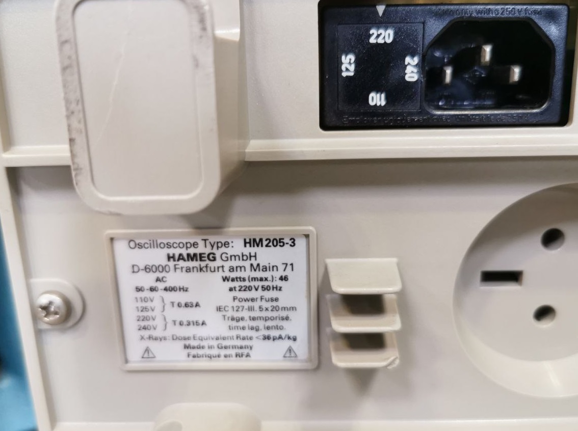
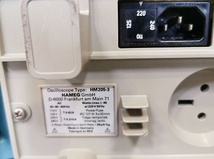
Oscilloscope Type: HM205-3
HAMEG GmbH
D-6000 Frankfurt am Main 71
Watts (max.): 46
at 220 V 50 Hz
AC 50-60-400 Hz
110V T 0.63A
125V
220V T 0.315A
240V
IEC 127-III. 5x20mm
träge, temporisé,
time lag, lento
X-Rays: Dose Equivalent Rate < 36 pA/kg
Made in Germany
Fabrique en RFA
Semiconductors Product specification NPN power transistors BD135; BD137; BD139 FEATURES PINNING • High current (max. 1.5 A) PIN DESCRIPTION • Low voltage (max. 80 V). 1 emitter 2 collector, connected to metal part of APPLICATIONS mounting surface 3 base • Driver stages in hi-fi amplifiers and television circuits.
Amplifiers 1.4 Quick reference data Table 2. Quick reference data Symbol Parameter Conditions Min Typ Max Unit V collector-emitter voltopen base - - 80 V CEO IC collector current - - 1 A ICM peak collector currentsingle pulsep t ≤ 1 ms - - 1.5 A hFE DC current gain VCE = 2 V;CI = 150 mA 63 - 250 hFEselection
cubic inch density n N+1 redundancy capable, INPUT CHARACTERISTICS Parameter Conditions Min. Typ. Max. Units including hot-docking Input Voltage Operating Range 170 230 264 Vac n Active current sharing or droop current Input Frequency 47 55 63 Hz sharing Turn-on Input Voltage Ramp up 160 170 Vac Turn-off
TOM. There are two cases that give a transition without Compare Match. OCR0A changes its value from MAX, like in Figure 14-7. When the OCR0A value is MAX the OCn pin value is the same as the result of a down-counting Compare Match. To ensure symmetry around BOTTOM the OCn value at MAX must correspond
Internal slope. in_par_03 none Time constant of the internal bath. in_par_04 none Bandwidth limit (max. difference between the temperatures in the internal bath and external system). in_par_05 none Ratio for max. cooling capacity versus max. heating capacity. in_par_06 none Xp control parameter of the
aber: Natürlich ein Lötkolben (ca. 25 W, an Schutzleiter angeschlossen) und Elektronik-Lötzinn mit max. 1 mm Durchmesser. Bei wenig Löterfahrung bitte nicht gleich am Shield löten „üben“, sondern an einem Stück Streifenrasterplatine (z. B. Reichelt Streifenrasterplatine) und einigen Drahtstücken. Im
können. Gibt es ab 10 € bis 12 €. Seitenschneider (Empf.: Knipex), Abisolierzange (Empf.: Stanely FatMax), Flachzange Presszange für Flachbandkabel und Steckverbindung für 16pol Pfostenbuchse Schraubendreherset, Pinzette, Biegehilfe für Widerstände ... Sorgfalt und Geduld: Es ist nicht viel Aufwand, z.
bei deiner Denkweise überhaupt richtig verstanden hast, ist auch noch fraglich. Bereitgestellte Max-Leistung ist doch wohl ein schwamminger Ausdruck, max. Anschlußleistung der Hausanschlusses soll es doch heißen?
Maximalleistung. Moderne Messeinrichtungen (digitale Stromzähler, muss kein SmartMeter sein) messen die max. Last im 15 Minuten Intervall. Die max. Last wird dann jeden Monat gespeichert. Somit kann die max. Last im Jahr ermittelt werden. Danach richtet sich dann deine Grundgebühr. Hier ein Beispiel für
irgendwo fratze sein. Besonders einfach wird es, wenn Du die Zeit tau misst, bis der Strom auf 63% von I0 angestiegen ist (z.B. mit dem Komparator des ATmega). Dann gilt nämlich: [math] \tau_{63\%} = L/R \Rightarrow L = \tau_{63\%} * R \\ \tau_{63\%} : ~~~~~ \text{Zeit, in der} I \text{
Feature Pb Free Solder Process Non-Pb Free Solder Process Average Ramp Up Rate (T to T ) 3°C / second Max. 3°C / Second Max. s p Preheat - Temperature Min (T sin.) 100°C 150°C - Temperature Max (T sax.) 150°C 200°C - Time (tsMin to s Max) 60 to 120 seconds 60 to 120 seconds Time Maintained Above Critical
2m 0.75mm2) bis 16A: 1.5mm2 (bis 2m 1mm2) bis 25A: 2.5mm2 bis 32A: 4mm2 bis 40A: 6mm2 bis 63A: 10mm2 [/pre] Daher sind viele Gerätezuleitungen nicht über 2m lang" Kaltgerätekabel sind nur für 10A.
bleibt aufgerollt, zusammengeknäuelt oder was auch immer, nur ganz sicher (jedenfalls bei mehr als max. 'nem Meter Überlänge) nie so verteilt zum liegen, daß sich dadurch kein 'Wärmestau' bilden kann. So scheinen mir 2m im Endeffekt als recht praktischer Kompromiss: im Haushalt in den meisten Fällen
Depth : 237 mm (9.33'') SOG (Sync On Green) Height : 428 mm (16.85'') -Min Digital 508 mm (19.99'') -Max 3-2. Video Input Signal 1) Type : R, G, B Analog 7. WEIGHT (with SPEAKER) 2) Voltage Level : 0~0.71 V Net. Weight : 8.8kg (19.40 lbs) a) Color 0, 0 : 0 Vp-p Gross Weight : 11.3kg (24.91 lbs) b) Color
PD-97594 IRLR6225PbF ® HEXFET Power MOSFET V 20 V DS R D D DS(on) max 4.0 mΩ (@V GS= 4.5V) R DS(on) max 5.2 S (@V GS= 2.5V) mΩ G G Q g (typical) 48 nC D-Pak S IRLR6225PbF RG (typical) 2.2 Ω D 42 h A G D S Gate Drain Source Applications • Battery Protection Switch Features
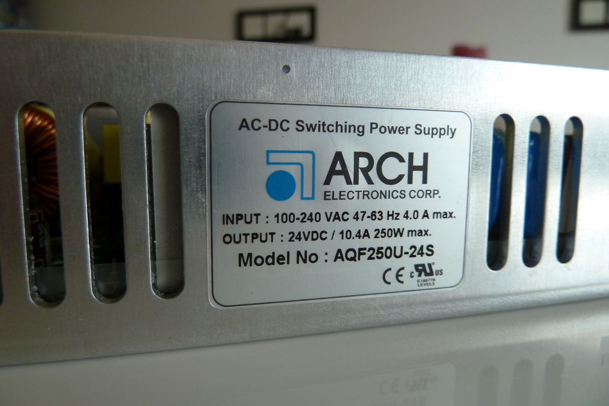
ELECTRICAL SPECIFICATIONS Model No. AQF250U-3.3S AQF250U-5S AQF250U-12S AQF250U-15S AQF250U-24S AQF250U-48S Max Output Wattage (18CFM FAN) (W) 132W 200W 250W 250W 250W 250W 105W 160W 200W 200W 200W 200W Max Output Wattage (W) Voltage 90-264 VAC or 120-370 VDC Frequency (Hz) 47-63 Hz Current (Full load) 4 .0 A max. (115 VAC) / 2.0 A max. (230 VAC) Input Inrush Current (<2ms) 40 A max. (115 VAC) / 80 A max. (230 VAC) Leakage Current 3.5 mA max. Power Factor PF>0.97 (115 VAC) / PF>0.93 (230 VAC) at Full Load Voltage
findest Du auf S.259 den "Input Leakage Current" für den Fall, dass der Eingang auf 5,5V liegt (also die max. Spannung dort anliegt) mit 1uA angegeben. Das wäre dann der max. Strom, der im Falle von HIGH durch R2 in Deinen Arduino fließt. Der Pegelwandler benötigt also in diesem Fall tatsächlich max. 1uA
Microtower Small Form Factor PCI slots 2 Full Length 5V 32 bit PCI slots 2 LP 5V 32 bit PCI slots Max power per slot 25W 25W PCIe x1 slot 1 1 Max power per slot 10W 10W PCIe X16 slot 1 Full Height card 1 LP profile card Max power per slot 75W 25W External Bays 3.5" 1 1 5.25" 2 1 IDE Internal 3.5" HDD
Microtower Small Form Factor PCI slots 2 Full Length 5V 32 bit PCI slots 2 LP 5V 32 bit PCI slots Max power per slot 25W 25W PCIe x1 slot 1 1 Max power per slot 10W 10W PCIe X16 slot 1 Full Height card 1 LP profile card Max power per slot 75W 25W External Bays 3.5" 1 1 5.25" 2 1 IDE Internal 3.5" HDD
grôßeren Netzen. Ich kann bei > 32 Informationen später auch auf 29 Bit (2.0B) erweitern,weiß ich. @Max Schön, daß du auch was konstruktives beigetragen hast...

 Bild
Bild
 Bild
Bild
 Bild
Bild
 Bild
Bild
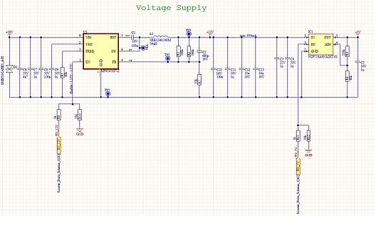
 Bild
Bild
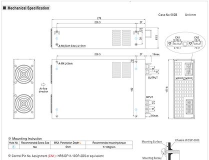
 Bild
Bild

 Bild
Bild
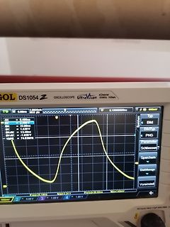
 Bild
Bild