
-
Datei
auto.vhd
clk,we0,we1,we2,sw0,sw1,sw2,ad); process(clk) begin if (clk='1' and clk'event) then case status is when "000" => ad <= adr1; we1 <= '1'; we0 <= '0'; sw1 <= '1'; status <= "001"; when "001" => ad <= adr2; we1 <= '0'; sw2 <= '1'; we2 <= '1'; status <= "010"; when "010" => ad <= adr1; we2 <= '0'; we0 <= '1'; sw0 <= '0'; status <= "011"; when "011" => ad <= adr2; we0 <= '1'; sw0 <= '1'; status <= "000"; when others => end case; end if; end process; end Behavioral;
-
Datei
VHDL_Code_Gustl__3.txt
downto 0) ); end SOURCE; architecture Behavioral of SOURCE is signal COUNT : unsigned(9 downto 0):=(others => '0'); signal Schalter_grenze : integer range 0 to 1023; begin Schalter_grenze <= to_integer(unsigned(SCHALTER( 9 downto 0))); -- Hier hab ich es umgewandelt process (CLK) begin if rising_edge(CLK
-
Datei
vhdl_code_emacs.vhd
downto 0) ); end SOURCE; architecture Behavioral of SOURCE is signal COUNT : unsigned(9 downto 0) := (others => '0'); signal Schalter_grenze : integer range 0 to 1023; begin Schalter_grenze <= to_integer(unsigned(SCHALTER(9 downto 0))); -- Hier hab ich es umgewandelt process (CLK) begin if rising_edge(CLK
-
PDF
avr443.pdf
which is sufficient for over-current detection as the voltage over a 0.22 ohm shunt resistor is 220mV when 1A flows through it. If required the ADC can be triggered by the PWM to measure current when not switching or run continuously with a given sampling frequency. A second ADC channel is used to measure
in „Verstädnisfrage zu einer MOSFET Schaltung“ · Mikrocontroller und Digitale Elektronik ·
-
Datei
cordic.vhd
clk'EVENT AND clk='1') THEN --------- Laden des nächsten Winkels --------- shift Werte CASE count IS WHEN "0000" => data := "001000000000"; -- 45.0000° I_shift:= (costemp(9) & costemp(9 DOWNTO 1)); Q_shift:= (sintemp(9) & sintemp(9 DOWNTO 1)); L<=1; WHEN "0001" => data := "000100101110"; -- 26.5650° I_shift
in „CORDIC in VHDL“ · FPGA, VHDL & Co. ·
-
Datei
LCD_daten.vhd
cs <='1'; o_cs <= '1'; FSM: process ( clk ) begin if rising_edge(clk) then case current_state is when S0 => if zaehler1 = 19 then rs <= '0'; rw <= '1'; current_state<= S1; end if; when s1 => if zaehler2 = 22 then rs <= '0'; rw <= '1'; csb <= '0'; e <= '1'; current_state<= s2; end if; when s2 => if zaehler3
-
Datei
top.txt
<= fsm_init ; when 1 => st_FSM <= fsm_H ; when 2 => st_FSM <= fsm_A ; -- wechseln in nächsten Zustand, abhängig von si_Hallo when 3 => st_FSM <= fsm_L ; when 4 => st_FSM <= fsm_L2 ; when 5 => st_FSM <= fsm_O ; when 6 => st_FSM <= fsm_end ; when others => st_FSM <= fsm_init ; end case; else st_FSM <= fsm_wait; end if; when fsm_H => s1_Steuer <= '1' ; s1_SPI_Enable <= '1'; st_FSM <= fsm_wait ; vi_Cnt_Wait := 200000 ; si_HALLO <= 2 ; when fsm_A
in „Textausgabe mittels SPI an Lattice FPGA“ · FPGA, VHDL & Co. ·
-
Datei
DDS.vhd
----------------- signal RESULT : signed (31 downto 0); signal ACCUM : unsigned (7 downto 0) := (others=>'0'); signal ADDRESS : integer range 0 to 63; signal ROMADDR : integer range 0 to 63; signal QUADRANT : std_logic; signal SIGN : std_logic; type signal_shape_LUT is array(64 downto 0) of std_logic_vector
in „DDS mit DE0-Nano Board nur niedrige Frequenzen?“ · FPGA, VHDL & Co. ·
-
PDF
doc8107.pdf
Corporation. All rights reserved. Atmel®, logo and combinations thereof, AVR®, STK®, AVR Studio® and others, are the registered trademarks or trademarks of Atmel Corporation or its subsidiaries. Windows® and others are registered trademarks or trademarks of Microsoft Corporation in the US and/or other countries. Other terms and product names may be trademarks of others. 8107A-AVR-04/08
in „STK 600 und AVR Studio - Welche µC kann ich damit programmieren?“ · Mikrocontroller und Digitale Elektronik ·
-
Datei
test.vhd
-- Programm reagiert nur bei positiver Flanke des Clocks case SCHALTER is -- Zuweisen des Errors when "0000" => when "0001" => when "0010" => when "0100" => when "1000" => when others => -- Wenn 2 oder mehr Schalter aktiviert sind, wird der Error ausgelöst ERROR <= '1'; end case; if RESET = '1' then
in „Addition & Multiplikation mit FPGA“ · FPGA, VHDL & Co. ·
-
Datei
Kaffeeautomat_V0c.vhd
GeldAusgeben : std_logic := '0'; begin -- Einsynchronisieren Pr50Csr <= Pr50Csr(3 downto 0)&Pruefer50Cent when rising_edge(clk); Pr1Esr <= Pr1Esr(3 downto 0) &Pruefer1Euro when rising_edge(clk); Pr2Esr <= Pr2Esr(3 downto 0) &Pruefer2Euro when rising_edge(clk); -- Flankenerkennung Pr50C <= '1' when Pr50Csr(4 downto 1) = "0111" else '0'; Pr1E <= '1' when Pr1Esr(4 downto 1) = "0111" else '0'; Pr2E <= '1' when Pr2Esr(4 downto 1) = "0111" else '0'; process begin wait until rising_edge(clk); -- default: nicht ausgeben R1E <= '0'; R50C <= '0'; -- Geldzähler
-
Datei
Kaffeeautomat_Variable.vhd
KaffeeUndGeldAusgeben : std_logic := '0'; begin -- Einsynchronisieren Pr50Csr <= Pr50Csr(3 downto 0)&Pruefer50Cent when rising_edge(clk); Pr1Esr <= Pr1Esr(3 downto 0) &Pruefer1Euro when rising_edge(clk); Pr2Esr <= Pr2Esr(3 downto 0) &Pruefer2Euro when rising_edge(clk); -- Flankenerkennung Pr50C <= '1' when Pr50Csr(4 downto 1) = "0111" else '0'; Pr1E <= '1' when Pr1Esr(4 downto 1) = "0111" else '0'; Pr2E <= '1' when Pr2Esr(4 downto 1) = "0111" else '0'; process variable gz : integer range 0 to 6; begin wait until rising_edge(clk); gz := Geldzaehler; if Pr50C
-
 Bild
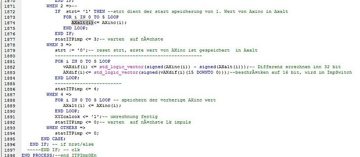
Programmcode in einer Entwicklungsumgebung
1870 END IF; 1871 WHEN 2 =>-- 1872 IF strt='1' THEN --strt dient der start speicherung von 1. Wert von Axinc in Axalt 1873 FOR i IN 0 TO 5 LOOP 1874 Axalt(i)<= Axinc(i); 1875 END LOOP; 1876 END IF; 1877 statITPimp <= 3;--
in „Post-Map simulation mit ModelSim“ · FPGA, VHDL & Co. · · Screenshots
-
Datei
Rechenwerk.vhd
to_integer(unsigned(A)); x<= to_integer(signed(B)); begin werk:process(A,B,clk,mode) begin case mode is when "00" => y<=t+x; when "01" => y<=t+2*x; when "10" => y<=2*t-x; when others => null; end case mode; if y>= 0 and y<=10 then gr<='1'; ge<='0'; rt<='0'; elsif y>=11 and y<=20 then gr<='0'; ge<='1'; rt<=
in „Gray Code und Zweierkomplement Addition“ · FPGA, VHDL & Co. ·
-
PDF
sluaa58.pdf
where a battery disconnect switch or circuit breaker is needed. 5 V or Temp Temp To Non-Isolated others Amplifier / HallTo MCU Buck / LDO 5 V or Amplifier / Hall MCU DC/DC Sensor Sensor Sensor others Sensor Primary Secondary Secondary Primary Sensing Primary Current Temp Temp Current Sensing Secondary
in „Halbbrücke Gate-Treiber Erklärung“ · Analoge Elektronik und Schaltungstechnik ·
-
PDF
STEPPII_55_56_LT_hardware_manual_ver_1.01.pdf
and regulations on the use of cellular devices in the area where you drive. Always obey them. Also, when using your modem while driving, please pay full attention to driving, pull off the road and park before making or answering a call if driving conditions so require. When applications are prepared for
in „Frage an die GPS- ( Ortungsspezialisten)“ · Mikrocontroller und Digitale Elektronik ·
-
PDF
AVR315_Using_the_TWI_module_as_I2C_master.pdf
data byte • After a STOP or REPEATED START has been received while still addressed as a Slave. • When a bus error has occurred due to an illegal START or STOP condition Bit Rate Generator The Bite Rate Generator unit controls the period of SCL when operating in a Master mode. The SCL period is controlled
in „ATTiny2313 I2C - Master (Peter Fleury) / Slave (jtronics)“ · Mikrocontroller und Digitale Elektronik ·
-
Datei
Modem.vhd
", four when "100000", three when "100001", two when "100010", one when "100011", minus_one when "100101", minus_two when "100110", minus_three when "100111", three when "011000", two when "011001", one when "011010
-
Datei
Modem.vhd
", four when "100000", three when "100001", two when "100010", one when "100011", minus_one when "100101", minus_two when "100110", minus_three when "100111", three when "011000", two when "011001", one when "011010
-
Datei
Modem.vhd
", four when "100000", three when "100001", two when "100010", one when "100011", minus_one when "100101", minus_two when "100110", minus_three when "100111", three when "011000", two when "011001", one when "011010
-
Datei
OneBitAlu.vhd
end if; else AV := '0'; end if; if ENB = '1' then BV := B; else BV := '0'; end if; case F is -- AND when "00" => Y <= AV AND BV; -- OR when "01" => Y <= AV OR BV; -- NOT B when "10" => Y <= NOT BV; -- A + B when "11" => SUM := ("0"&AV) + ("0"&BV) +("0"&Cin); Y <= SUM(0); Cout <= SUM(1); when others =>
-
PDF
doc2559.pdf
deviation of the actual ADC’s transfer function from the ideal straight line at zero input voltage. When the transition from output value 0 to 1 does not occur at an input value of ½ LSB, then we say that there is an offset error. With positive offset errors, the output value is larger than 0 when the
in „ADC-Wert nicht linear beim Einlesen“ · Mikrocontroller und Digitale Elektronik ·
-
PDF
vhdl2proc.pdf
allow specifications (or models) from different providers (compa- nies) to be simulated together. When the language was first put to use, it was used for high-level behavioural simula- tion only. ’Synthesis’ into VLSI devices was made by manually converting the models into schematics using gates and
in „VHDL Grundlagen : zwei Prozess Methode“ · FPGA, VHDL & Co. ·
-
Datei
ddr_init.vhd
-------- when Precharge0 => SD_CMD <= CMD_PRECHARGE; SD_A(10) <= '1'; -- Precharge all operation. iin.s <= Precharge0Wait; -- PRECHARGE command period tRP: 15ns when Precharge0Wait => if i.c = 1 then iin.c <= 0;
-
PDF
ESCVP21_e_P.pdf
Network on 8300/8350/9300 Null command(note1) (note1) 7900/7950 Network off (note3) PWR ON(Note2) Others - EMP-61/81/830/835/740/745/821/828 returns “ERR” when it received commands other than PWR ON, PWR?, LAMP? and Null commands. (note2) EMP-7800/7850 returns “ERR” when it received commands other than
in „1->3 RS232 Splitter µC gesteuert“ · Mikrocontroller und Digitale Elektronik ·
-
PDF
Sharp_LQ065T5AR01.pdf
14 BRT i Brightness adjusting terminal 【Note5-10】 15 VR1 i Color video signal (Red)1 Positive (On when VSW=Hi.) 16 VG1 i Color video signal (Green)1 Ditto 17 VB1 i Color video signal (Blue)1 Ditto 18 GND1 i Ground 19 VR2 i Color video signal (Red)2 Positive (On when VSW=Lo.) 20 VG2 i Color video signal
in „Monitor Travel Pilot DX-V“ · Mikrocontroller und Digitale Elektronik ·
-
Datei
ser2par.vhd
out std_logic_vector (6 downto 0); -- parallel data output rdy : out std_logic; -- edge is issued when data word was updated reset : in std_logic); -- reset signal end entity ser2par; architecture ser2par_rtl of ser2par is signal sr0: std_logic_vector (3 downto 0); -- signal for uneven bits signal sr1
in „Seriell-Parallel-Wandlung mit VHDL“ · FPGA, VHDL & Co. ·
-
Datei
COUNTER.vhd_COUNTER_TB.vhd
: PROCESS(CURRENT_STATE) --Vorgehen, beim Wechsel des Current-States. begin case CURRENT_STATE is when IDLE => RESULT_OUT <= "1111"; when STATE0 => NEXT_STATE <= STATE1; RESULT_OUT <= "0000"; when STATE1 => NEXT_STATE <= STATE2; RESULT_OUT <= "0001"; when STATE2 => NEXT_STATE <= STATE3; RESULT_OUT <= "0010"; when STATE3 => NEXT_STATE <= STATE0; RESULT_OUT <= "0011"; when others => NEXT_STATE <= STATE0; end case; end PROCESS STATE_DECODER; REG: PROCESS(CLK, RESET, START_STOP) begin if(RESET ='0') then -- Reset
-
PDF
atmel_32uc.pdf
Workaround Do not set FDIV = 1. 70 AT32UC3A 3. SPI Bad Serial Clock Generation on 2nd chip_select when SCBR = 1, CPOL=1 and NCPHA=0 When multiple CS are in use, if one of the baudrate equals to 1 and one of the others doesn't equal to 1, and CPOL=1 and CPHA=0, then an aditional pulse will be generated
in „V: ATMEL 32UC3A0512-U“ · Markt ·
-
Datei
memorytest1.vhdl
rising_edge(clk) then if ctr = 127 then ctr <= 0; else ctr <= ctr + 1; end if; case ctr mod 8 is when 4 => ram_addr <= std_logic_vector(to_unsigned(ctr / 8, 4)); when 5 => ram_en <= '1'; when 6 => ram_en <= '0'; when 7 => shiftreg <= ram_data; when others => null; end case; end if; end process; process
-
PDF
Skript_Praktikum_Rechnerarchitektur.pdf
"010", d when "011", e when others; Seite 17 | Prof. Dr.-Ing. Ulrich Schmidt | 2011 Praktikum Rechnerarchitektur Versuch 2: hierarchisches Design a) Ansteuerung einer Siebensegmentanzeige Entwerfen Sie einen Decoder
in „Clockmultiplexing vom mehreren Taktsignalen“ · FPGA, VHDL & Co. ·
-
PDF
OVC3860_RevE_PSKeys_Setting_v1.2.pdf
, circuit described herein; neither does it convey any license under its patent nor the right of others. The datasheet is the official document of OmniVision. The applicaton notes are application guide lines for reference. If there are any difference between sensor datasheet and application notes, please
in „A2DP Bluetooth Modul China eBay“ · HF, Funk und Felder ·
-
PDF
OVC3860_RevE_PSKeys_Setting_v1.2.pdf
, circuit described herein; neither does it convey any license under its patent nor the right of others. The datasheet is the official document of OmniVision. The applicaton notes are application guide lines for reference. If there are any difference between sensor datasheet and application notes, please
in „OVC3860 RevV Develop Tool - not connected :/“ · HF, Funk und Felder ·
-
PDF
doc8057.pdf
bytes contained in the data packet. When the complete flag for the data packet is set, the master verifies that it has received the correct values. 5.3 Polled The polled code example uses the SPI driver to instantiate a master and slave. The
in „SPI auf Atxmega 256 A3 , wo ist die spi_driver.c“ · Mikrocontroller und Digitale Elektronik ·
-
PDF
AVR1304_Using_the_XMEGA_DMA_Controller.pdf
positions the source pointer back to the first ADC result register after the data transfer. Note that when using reload after a burst and the total byte count is not a multiple of the burst size, the last burst transfer will stop when the total byte count is reached, and the reload action occurs. For example
in „Wie funktioniert der DMA am Xmega“ · Mikrocontroller und Digitale Elektronik ·
-
Datei
joblist.vhd
15 downto 0); Job: process begin wait until rising_edge(clk); Error <= '0'; case CommandAdress is when x"0001" => Value1 <= CommandValue; sMemAdress <= sMemAdress+1; when x"0002" => Value2 <= CommandValue; sMemAdress <= sMemAdress+1; when x"0003" => Value3 <= CommandValue; sMemAdress <= sMemAdress+1; when others => Error <= '1'; end case; end process Job; MemAdress <= std_logic_vector(to_unsigned(sMemAdress, MemAdress'length)); end Behavioral;
-
Datei
ADC_Clock_Generator.vhd
; end if; when 7 => ADC_Clk_Pin_i <= '1'; ADC_CS_Pin_i <= '1'; ldvalue_sys_cnt <= 42; ld_sys_cnt <= '1'; ldvalue_adc_cnt <= 0; ld_adc_cnt <= '0'; NSchritt <= 8; when 8 => ADC_Clk_Pin_i <= '1'; ADC_CS_Pin_i <= '1';
in „Mehrfache Instanziierung ein Komponente“ · FPGA, VHDL & Co. ·
-
Datei
top_HALLO.vhd
<= fsm_init ; when 1 => st_FSM <= fsm_H ; when 2 => st_FSM <= fsm_A ; -- wechseln in nächsten Zustand, abhängig von si_Hallo when 3 => st_FSM <= fsm_L ; when 4 => st_FSM <= fsm_L2 ; when 5 => st_FSM <= fsm_O ; when 6 => st_FSM <= fsm_end ; when others => st_FSM <= fsm_init ; end case; else st_FSM <= fsm_wait; end if; when fsm_H => s1_Steuer <= '1' ; s1_SPI_Enable <= '1'; st_FSM <= fsm_wait ; vi_Cnt_Wait := 200000 ; si_HALLO <= 2 ; RS<='1'
in „Textausgabe mittels SPI an Lattice FPGA“ · FPGA, VHDL & Co. ·
-
Datei
ampels.vhd
ZAEHLER <= 0; elsif (ZAEHLER > 3 and FU_ANF_SET = 0) then FOLGE_Z <= REG6; ZAEHLER <= 0; end if; when REG6 => AUSGANG <= N_GE_RT -- Nebenampel ist gelb-rot der Rest ist rot if (ZAEHLER <= 1) then FOLGE_Z <= REG6; else FOLGE_Z <= REG7; ZAEHLER <= 0; end if; when REG7 => AUSGANG <= N_GRUEN -- Nebenampel
in „in VHDL 50MHz auf 2 Mhz runterteilen?“ · FPGA, VHDL & Co. ·
-
Datei
Spartan3DAC.vhd
DAC_CLR<='0'; send_counter<="00000"; dac_counter<="00"; adc_counter <= "000000"; when ampl_select => booted_up_ready<='0'; AMPL_CS <= '0'; rec_state <= ampl_send; spi_register(31 downto 24)<="01000100"; when ampl_send => booted_up_ready<='0'; --SPI_SCK <= clk_slow; SPI_MOSI <= spi_register
-
PDF
LCD240128A.pdf
pin for logic .(+5V) 4 V0 I Contrast control (VDD~VOUT) 5 /WR I Data write: Write data into T6963 when /WR is L. 6 /RD I Data Read: Read data from T6963 when /RD is L. 7 /CE I Chip enable for T6963: /CE must be L when CPU communicates with T6963 8 C/D I C/D /WR=L /RD =L L Data Write Data Read H Command
in „LCD240128A an PIC 18F4550“ · Mikrocontroller und Digitale Elektronik ·
-
PDF
LCD240128A_TouchLedsee_TC.pdf
pin for logic .(+5V) 4 V0 I Contrast control (VDD~VOUT) 5 /WR I Data write: Write data into T6963 when /WR is L. 6 /RD I Data Read: Read data from T6963 when /RD is L. 7 /CE I Chip enable for T6963: /CE must be L when CPU communicates with T6963 8 C/D I C/D /WR=L /RD =L L Data Write Data Read H Command
in „T6963c Ansteuerungsproblem“ · Mikrocontroller und Digitale Elektronik ·
-
Datei
memorytest2.vhdl
rising_edge(clk) then if ctr = 127 then ctr <= 0; else ctr <= ctr + 1; end if; case ctr mod 8 is when 4 => ram_addr <= std_logic_vector(to_unsigned(ctr / 8, 4)); wave <= shiftreg(7); shiftreg(7 downto 1) <= shiftreg(6 downto 0); when 5 => ram_en <= '1'; wave <= shiftreg(7); shiftreg(7 downto 1) <= shiftreg(6 downto 0); when 6 => ram_en <= '0'; wave <= shiftreg(7); shiftreg(7 downto 1) <= shiftreg(6 downto 0); when 7 => shiftreg <= ram_data; wave <= ram_data(7); when others => wave <= shiftreg(7); shiftreg(7 downto 1) <
-
PDF
cxd2951-commands.pdf
This command clears the position and resets the software. While some user-set parameters are held, others return to the default values. See Table 2.2. This command may shorten the position fix time when long-distance travel occurs from the last fixed position. Note NMEA message continues outputting the
in „DCF77 Auswertung (ein bisschen anders)“ · Mikrocontroller und Digitale Elektronik ·
-
Datei
C2RBuffer.vhd
log : process (r, write_enable, read_enable) variable v : reg_type; begin v :=r; case r.state is when idle => if write_enable = '1' then v.state := write; elsif read_enable = '1' then v.state := read; else v.state := idle; end if; when write => v.buff(to_integer(unsigned(add_read))) := data_in; v.state := idle; when read => data_out <= std_logic_vector(r.buff(to_integer(unsigned(add_read)))); v.state := idle; when others => v.state := idle; end case; rin <= v; end process log; end Verhalten;
in „Cannot read output ERROR mit ModelSim- warum?“ · FPGA, VHDL & Co. ·
-
Datei
LCD_daten.vhd
state_typ; begin if rising_edge(clk) and clk = '1' then next_state:= current_state; case current_state is when S0 => if zaehler1 >= 19 then rs <= '0'; rw <= '1'; NEXT_state:= S1; end if; when s1 => if zaehler2 >= 1 then rs <= '0'; rw <= '1'; csb <= '0'; Next_state:= s2; end if; when s2 => if zaehler3 >= 4 then
-
Datei
LCD_daten.vhd
variable Next_state : state_typ; begin --if rising_edge(clk) and clk = '1' then case current_state is when S0 => if zaehler1 >= 19 then rs <= '0'; rw <= '1'; current_state<= S1; end if; when s1 => if zaehler2 >= 2 then rs <= '0'; rw <= '1'; csb <= '0'; current_state<= s2; end if; when s2 => if zaehler3 >
-
Datei
LCD_daten.vhd
cs <='1'; o_cs <= '1'; FSM: process ( clk ) begin if rising_edge(clk) then case current_state is when S0 => if zaehler1 >= 19 then rs <= '0'; rw <= '1'; current_state<= S1; end if; when s1 => if zaehler2 >= 2 then rs <= '0'; rw <= '1'; csb <= '0'; current_state<= s2; end if; when s2 => if zaehler3 >
-
Datei
LCD_daten.vhd
cs <='1'; o_cs <= '1'; FSM: process ( clk ) begin if rising_edge(clk) then case current_state is when S0 => if zaehler1 >= 19 then rs <= '1'; rw <= '0'; e <= '0'; current_state<= S1; end if; when s1 => if zaehler2 >= 2 then rs <= '0'; rw <= '1'; csb <= '0'; current_state<= s2; end if; when s2 => if
-
PDF
NCP5104-D.PDF
propagation delay (Vbridge = 0 V or 50 V) (Note 3) t − 100 170 ns OFF Shutdown propagation delay, when Shutdown is enabled t − 100 170 ns sd_en Shutdown propagation delay, when Shutdown is disabled t − 620 800 ns sd_dis Output voltage rise time (from 10% to 90CC@= 15 V) with 1 nF load r − 85 160 ns Output
in „Suche SMD Bauteil“ · Analoge Elektronik und Schaltungstechnik ·
