-
Thread
Dual Port Ram als Block Ram
das nicht alle an einer Kreuzung "Grün" bekommen. (Anhang aus http://web.mit.edu/neboat/Public/6.111_final_project/code/blk_mem_gen_ds512.pdf)
-
Thread
SMD Bauteile identifizieren
BCR402W > Bauteil 2: ML9U, SOT-23, Funktion unklar - auf der Platine als "IC" > bezeichnet MCP111T-450E > Bauteil 3: RDB, SOT-23, Funktion unklar - auf der Platine als "D" > bezeichnet BZB84B47 oder LM4050BIM3-4.1
-
 Bild
Bild
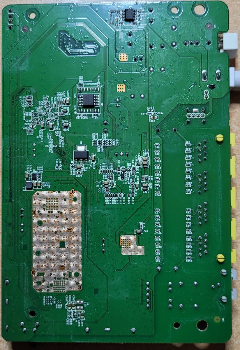
Grüne Leiterplatte mit Bestückungsdruck
C101, C102, C103, C104, C105, C106, C107, C108, C109, C110, C111, C112, C113, C114, C115, C116, C117, C118, C119, C120, C121, C122, C123, C124, C125, C126, C127, C128, C129, C130, C131, C132, C133, C134, C135, C136, C137, C138, C139, C140, C141, C142, C143, C144,
-
 Bild
Bild
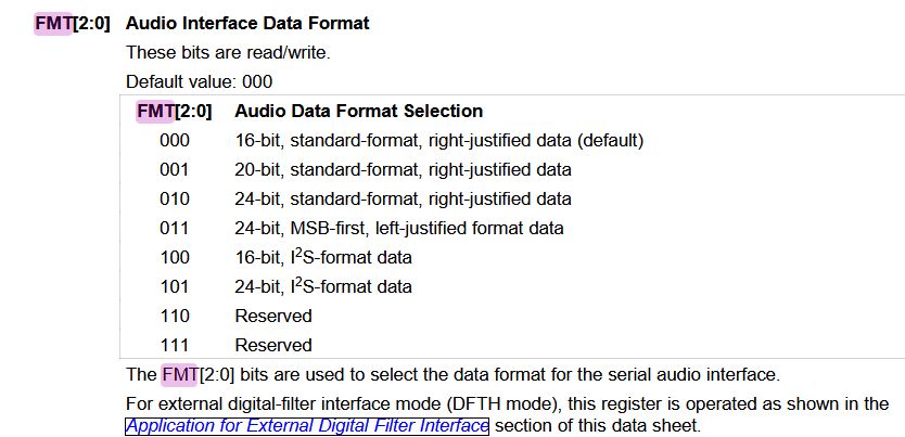
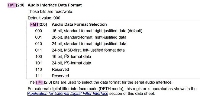
Ausschnitt aus einem Datenblatt zum Audio Interface Data Format
MSB-first, left-justified format data 100 16-bit, I2S-format data 101 24-bit, I2S-format data 110 Reserved 111 Reserved The FMT[2:0] bits are used to select the data format for the serial audio interface. For external digital-filter interface mode (DFTH mode), this register is operated as shown in the Application
-
 Bild
Bild
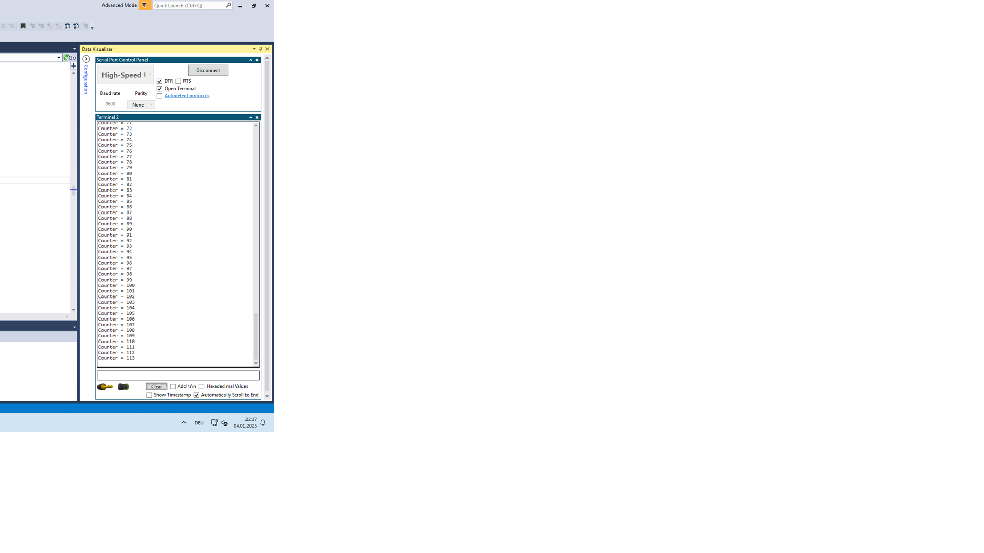
Software-Screenshot einer Terminal-Anwendung mit Datenliste
Counter = 91 Counter = 94 Counter = 97 Counter = 100 Counter = 102 Counter = 105 Counter = 108 Counter = 111 Counter = 115 Clear Add Hexadecimal Values Show Timestamp Automatically Scroll to End DEU 04.01.2025
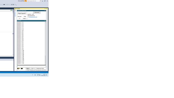
-
 Bild
Bild
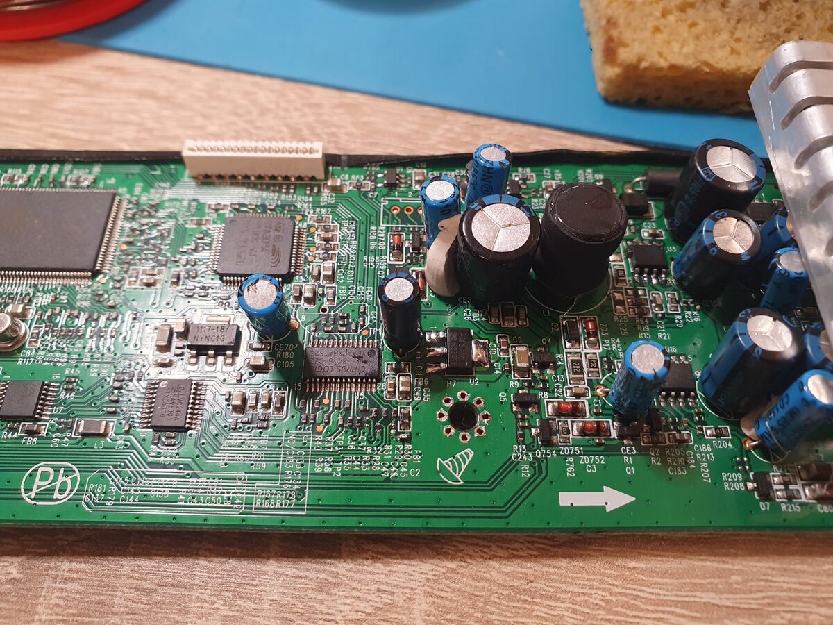
Foto einer bestückten Leiterplatte mit elektronischen Bauteilen
C89 C90 C91 C92 C93 C94 C95 C96 C97 C98 C99 C100 C101 C102 C103 C104 C105 C106 C107 C108 C109 C110 C111 C112 C113 C114 C115 C116 C117 C118 C119 C120 C121 C122 C123 C124 C125 C126 C127 C128 C129 C130 C131 C132 C133 C134 C135 C136 C137 C138 C139 C140 C141 C142 C143 C144 C145 C146 C147 C148 C149 C150 C151
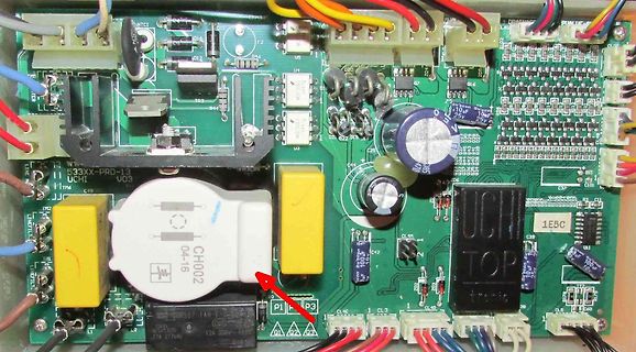
-
 Bild
Bild
Foto einer Leiterplatte mit elektronischen Bauteilen
R89 R90 R91 R92 R93 R94 R95 R96 R97 R98 R99 R100 R101 R102 R103 R104 R105 R106 R107 R108 R109 R110 R111 R112 R113 R114 R115 R116 R117 R118 R119 R120 R121 R122 R123 R124 R125 R126 R127 R128 R129 R130 R131 R132 R133 R134 R135 R136 R137 R138 R139 R140 R141 R142 R143 R144 R145 R146 R147 R148 R149 R150 R151
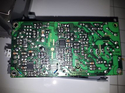
-
 Bild
Bild
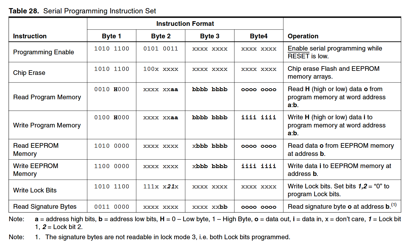
Tabelle Serial Programming Instruction Set
xxxx xxxx xbbb bbbb iiii iiii Write data i to EEPROM memory at address b. Write Lock Bits 1010 1100 111x x21x xxxx xxxx xxxx Write Lock bits. Set bits 1,2 = "0" to program Lock bits. Read Signature Bytes 0011 0000 xxxx xxxx xxbb bbbb oooo oooo Read signature byte o at address b. Note: a = address high
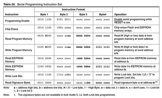
-
 Bild
Bild
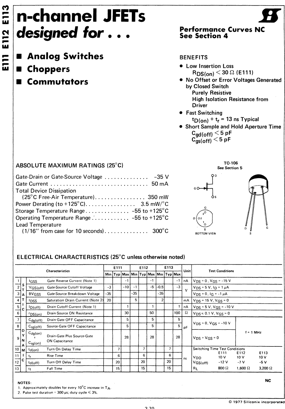
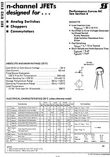
Datenblatt Ausschnitt n-channel JFETs E111 E112 E113
Operating Temperature Range -55 to +125°C. ELECTRICAL CHARACTERISTICS (25°C unless otherwise noted): E111, E112, E113. TO-16. SGS Silicon Incorporated.
-
 Bild
Bild
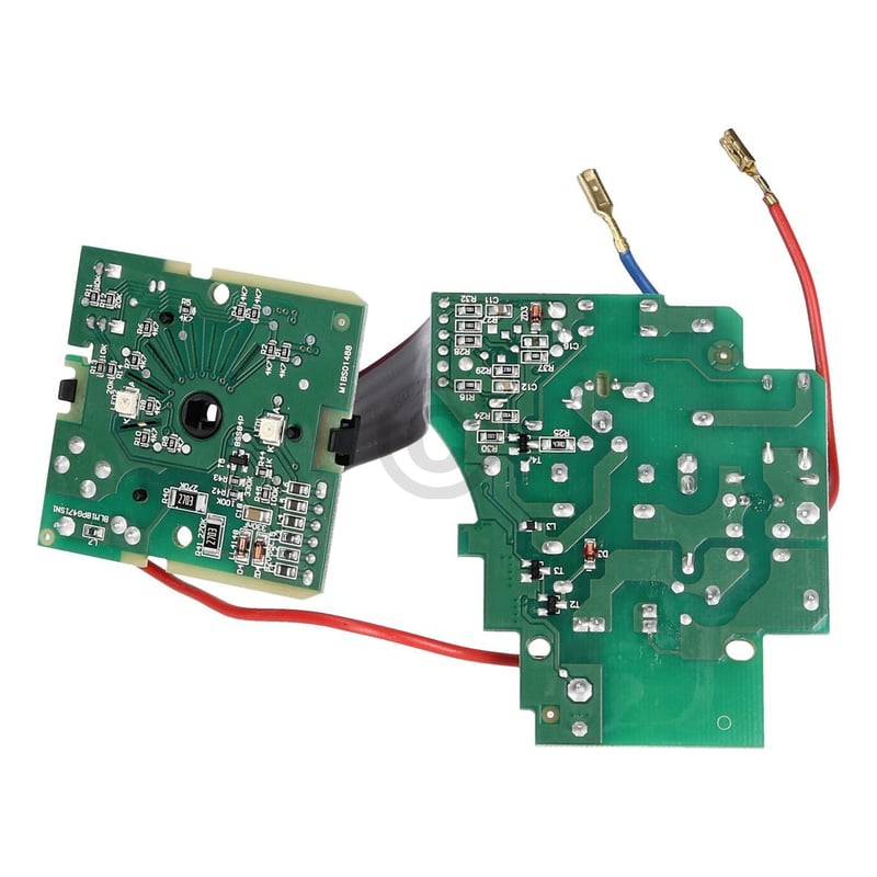
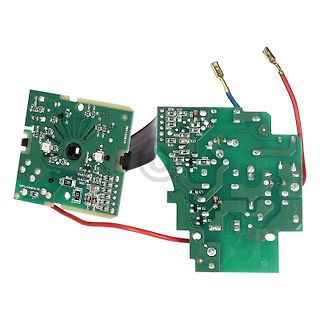
Zwei grüne Leiterplatten mit Kabeln und Steckern
, R94, R95, R96, R97, R98, R99, R100, R101, R102, R103, R104, R105, R106, R107, R108, R109, R110, R111, R112, R113, R114, R115, R116, R117, R118, R119, R120, R121, R122, R123, R124, R125, R126, R127, R128, R129, R130, R131, R132, R133, R134, R135, R136, R137, R138, R139
-
 Bild
Bild
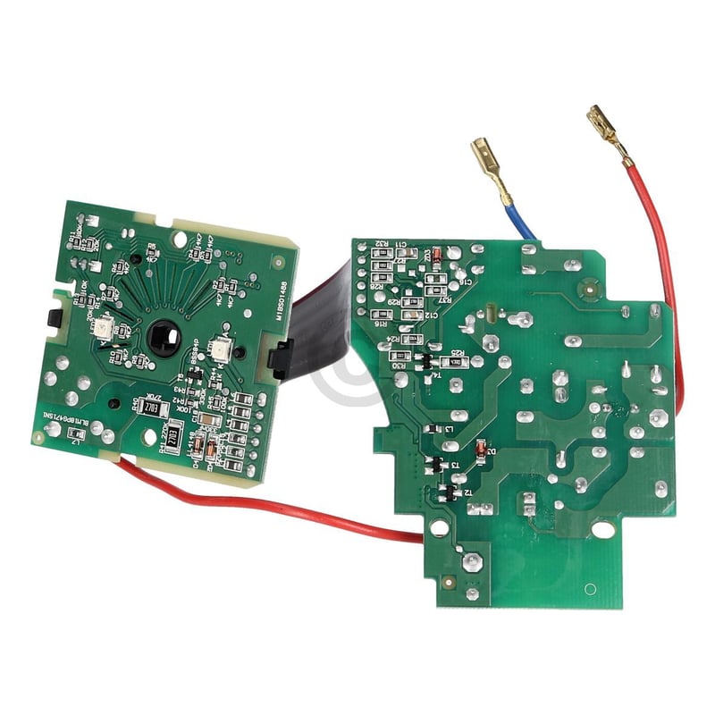
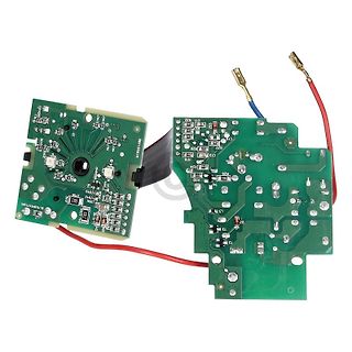
Zwei grüne Leiterplatten mit Kabeln und Steckern
, R94, R95, R96, R97, R98, R99, R100, R101, R102, R103, R104, R105, R106, R107, R108, R109, R110, R111, R112, R113, R114, R115, R116, R117, R118, R119, R120, R121, R122, R123, R124, R125, R126, R127, R128, R129, R130, R131, R132, R133, R134, R135, R136, R137, R138, R139
-
Thread
Sammelbestellung USBTMC Adapter. Interesse?
Ungenauigkeit. Es ist REV2 bestückt mit allen SMD Bauteilen und dem unbestückten Stecker ( NorComp Inc. 111-024-113L001 ). 73
-
 Bild
Bild
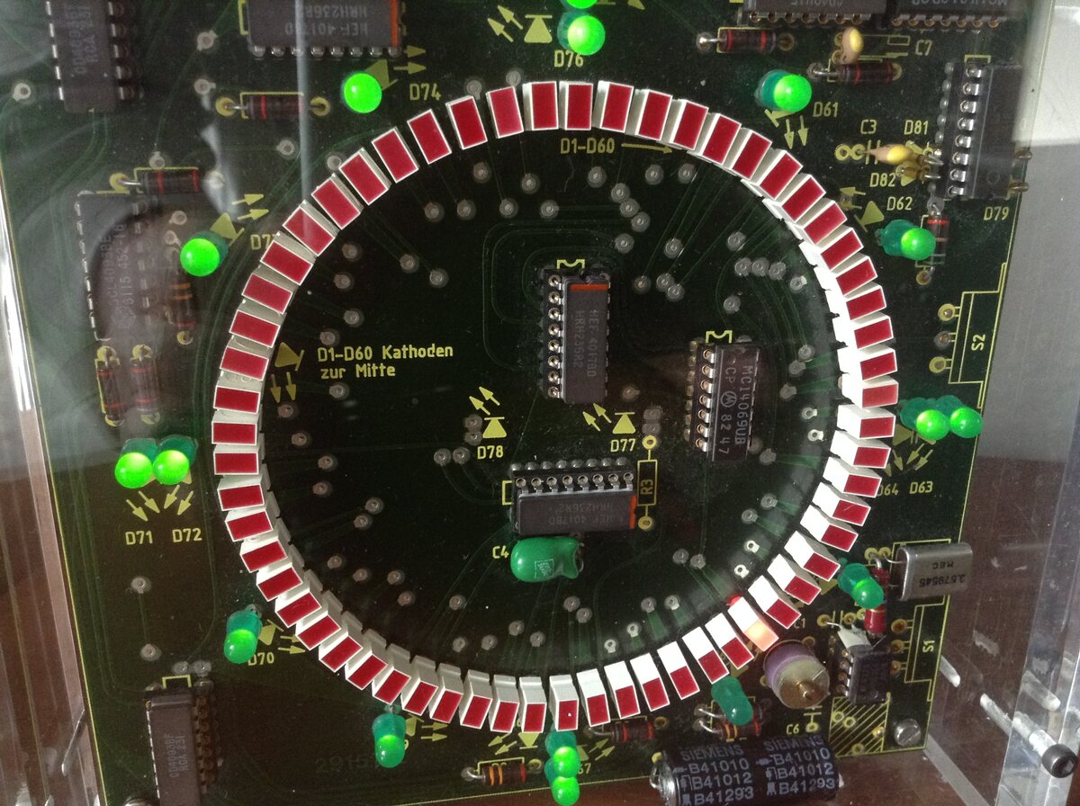
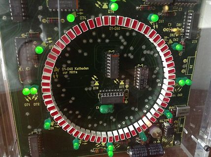
Foto einer kreisförmigen LED-Leiterplatte
D89 D90 D91 D92 D93 D94 D95 D96 D97 D98 D99 D100 D101 D102 D103 D104 D105 D106 D107 D108 D109 D110 D111 D112 D113 D114 D115 D116 D117 D118 D119 D120 D121 D122 D123 D124 D125 D126 D127 D128 D129 D130 D131 D132 D133 D134 D135 D136 D137 D138 D139 D140 D141 D142 D143 D144 D145 D146 D147 D148 D149 D150 D151
-
Thread
Netzteil-Regelung Stabilitätsanalyse "Loop Gain"
mit dem Schaltungsprinzip auseinander gesetzt hat: http://pegons-web.de/2power1.html#ui8 (ab Bild 111). Die 12V Spannungesquellen und den Ground habe ich verschoben. Wo ich mir nicht sicher bin, für welches Signal ich den Buffer einsetzen soll? Für R8? Die Senseleitungen wie im Org. habe ich der
-
 Bild
Bild
Nahaufnahme einer Leiterplatte mit elektronischen Bauteilen
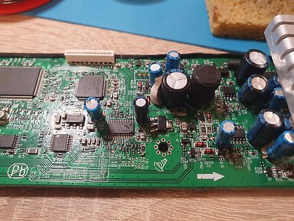
, R94, R95, R96, R97, R98, R99, R100, R101, R102, R103, R104, R105, R106, R107, R108, R109, R110, R111, R112, R113, R114, R115, R116, R117, R118, R119, R120, R121, R122, R12
-
 Bild
Bild
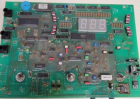
Leiterplatte mit 7-Segment-Anzeige und integrierten Bauteilen
, U94, U95, U96, U97, U98, U99, U100, U101, U102, U103, U104, U105, U106, U107, U108, U109, U110, U111, U112, U113, U114, U115, U116, U117, U118, U119, U120, U121, U122, U123, U124, U125, U126, U127, U128, U129, U130, U131, U
-
 Bild
Bild
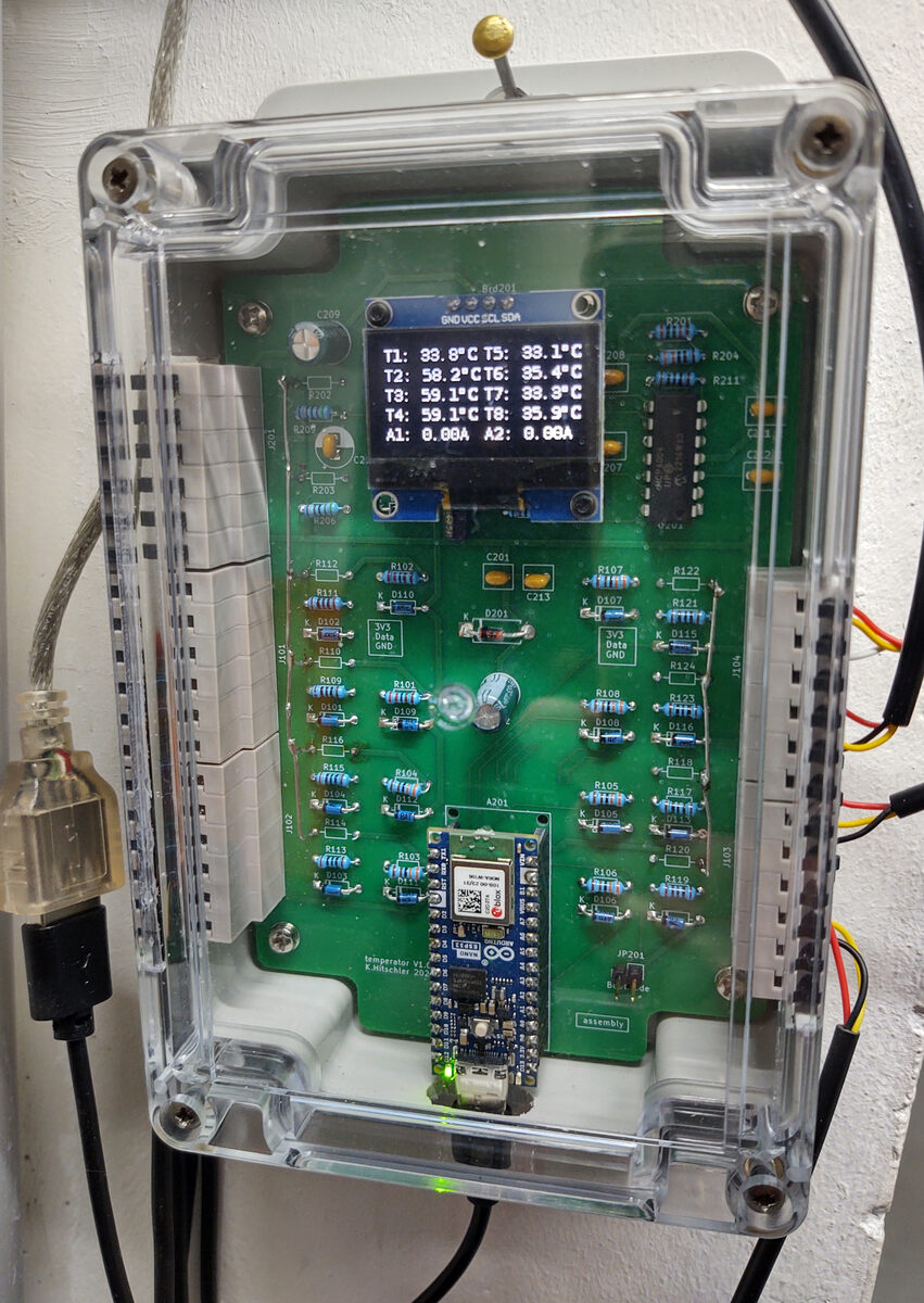
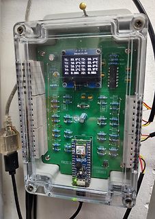
Elektronik-Projekt in transparentem Gehäuse mit Display
39.8°C T4: 59.1°C T8: 35.5°C A1: 0.00A A2: 0.69A R202 R203 R204 R211 R112 R102 C201 C213 R107 R122 R111 R103 D201 D109 R121 R106 R101 GND 3V3 R104 R123 R109 R101 R105 R118 R116 R108 R115 R105 R117 R103 R102 R104 R107 R105 R107 R103 R102 R104 R107 R105 R107 R103 R102 R104 R107 R105 R107 R103 R102 R104
-
Thread
FlipFlop mit Ge-Transistoren
logic_closeup.jpg Fotos von vielen älteren Platinen finden sich dort: http://www.wolfgangrobel.de/museum/iskra111.htm Dieser Wolfgang poltert auch hier im Forum: https://www.mikrocontroller.net/user/show/mikemcbike
-
 Bild
Bild
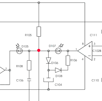
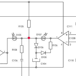
Schaltplan mit Dioden, Widerständen und Kondensatoren
R105 D105 R108 C106 D107 D106 R106 D108 C104 C104 C102B 8 1 4 2 C111 C110
-
 Bild
Bild
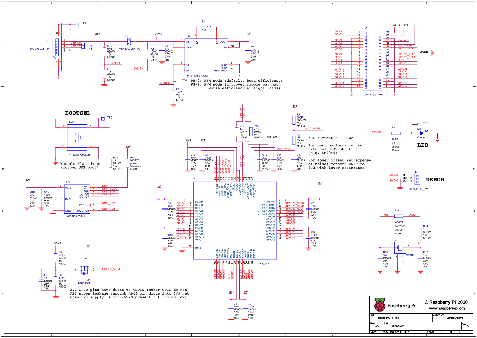
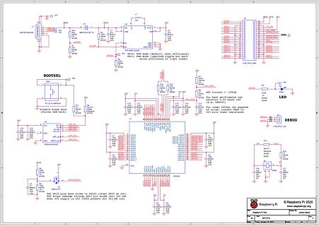
Schaltplan einer Raspberry Pi Erweiterung mit Boost-Konverter
, R94, R95, R96, R97, R98, R99, R100, R101, R102, R103, R104, R105, R106, R107, R108, R109, R110, R111, R112, R113, R114, R115, R116, R117, R118, R119, R120, R121, R122, R123, R124, R125, R126, R127, R128,
-
 Bild
Bild
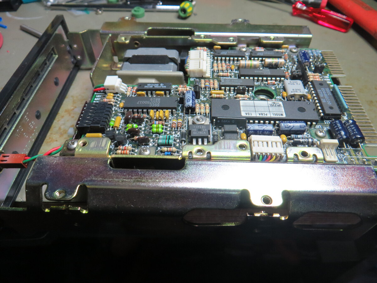
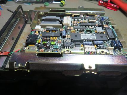
Innenansicht einer bestückten Leiterplatte in einem Metallgehäuse
MODEL PCA8 TOA, SGC50017, 101, 102, 103, 104, 105, 106, 107, 108, 109, 110, 111, 112, 113, 114, 115, 116, 117, 118, 119, 120, 121, 122, 123, 124, 125, 126, 127, 128, 129, 130, 131, 132, 133, 134, 135, 136, 137, 138, 139, 140, 141, 142, 143, 144, 145, 146, 147, 148, 149, 150, 151
-
 Bild
Bild
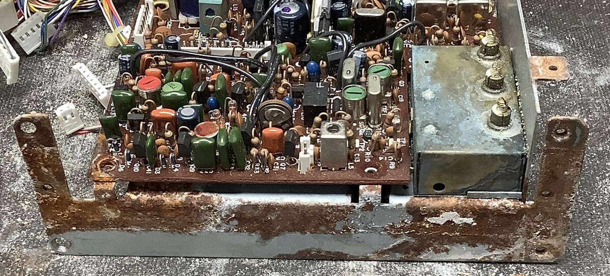
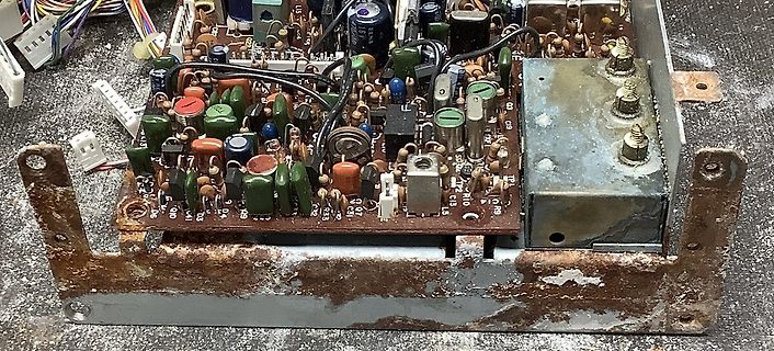
Verrostete Leiterplatte mit elektronischen Bauteilen
, C94, C95, C96, C97, C98, C99, C100, C101, C102, C103, C104, C105, C106, C107, C108, C109, C110, C111, C112, C113, C114, C115, C116, C117, C118, C119, C120, C121, C122, C123, C124, C125, C126, C127, C128, C129, C130, C131, C132, C133, C134, C135, C136, C137, C138, C139, C140, C14
-
 Bild
Bild
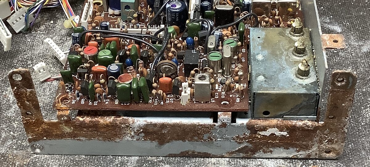
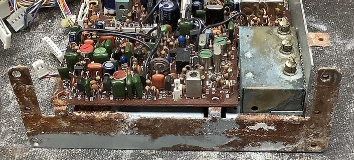
Verrostete Leiterplatte mit elektronischen Bauteilen
, C94, C95, C96, C97, C98, C99, C100, C101, C102, C103, C104, C105, C106, C107, C108, C109, C110, C111, C112, C113, C114, C115, C116, C117, C118, C119, C120, C121, C122, C123, C124, C125, C126, C127, C128, C129, C130, C131, C132, C133, C134, C135, C136, C137, C138, C139, C140, C14
-
Thread
Wer kann helfen, welche Baugruppe ist das?
ein größeres Boot gewesen sein. Da fehlen also noch etliche Baugruppen, wenn die Endröhre die HS2091-111 hat. Die Fotos sind leider Low Level. Arno
-
 Bild
Bild
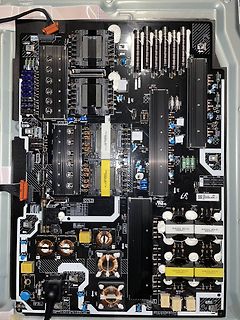
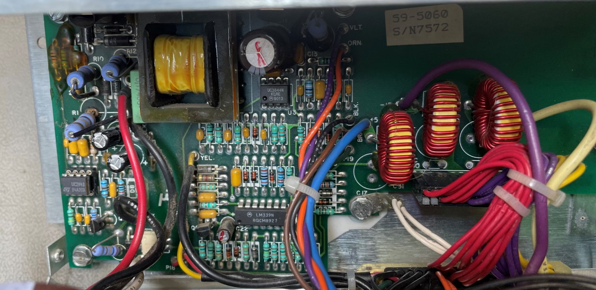
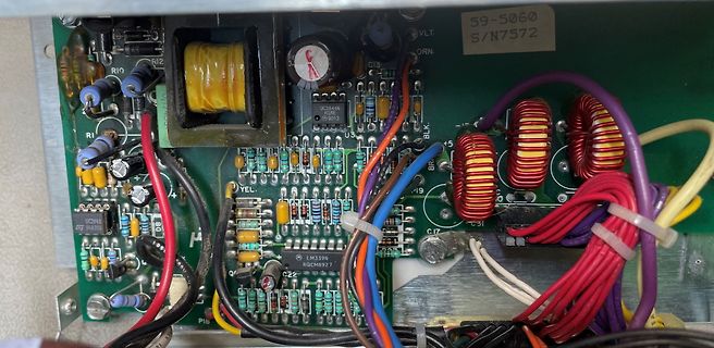
Innenansicht einer Leiterplatte mit Netzteilkomponenten
R89 R90 R91 R92 R93 R94 R95 R96 R97 R98 R99 R100 R101 R102 R103 R104 R105 R106 R107 R108 R109 R110 R111 R112 R113 R114 R115 R116 R117 R118 R119 R120 R121 R122 R123 R124 R125 R126 R127 R128 R129 R130 R131 R132 R133 R134 R135 R136 R137 R138 R139 R140 R141 R142 R143 R144 R145 R146 R147 R148 R149 R150 R151
-
 Bild
Bild
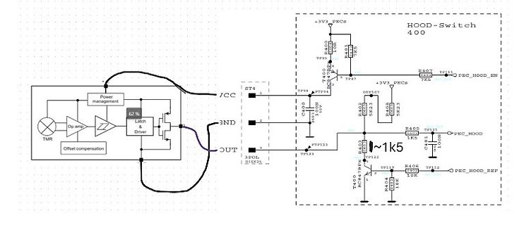
Schaltplan einer Hood-Switch-Steuerung
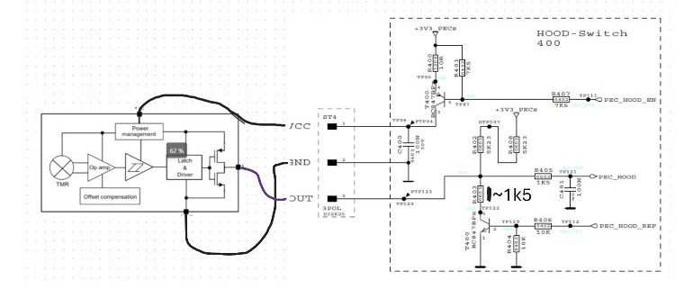
HOOD-Switch 400, +3V3 PECS, R400 10R, TP95, T400, TP47, R407 7K5, TP111, PEC_HOOD_EN, TP94, PECS, C400 100N, R402 5K2,7, TP127, GND, R405 6K9, TP133, PEC_HOOD, 1k5, R401 10K, TP123, OUT, 3POL, R404 10K, TP112, PEC_HOOD_REF, T400, TP122, R406, C401 100N, Power management
-
 Bild
Bild
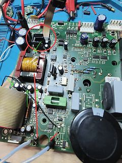
Foto einer bestückten Leiterplatte mit Markierungen
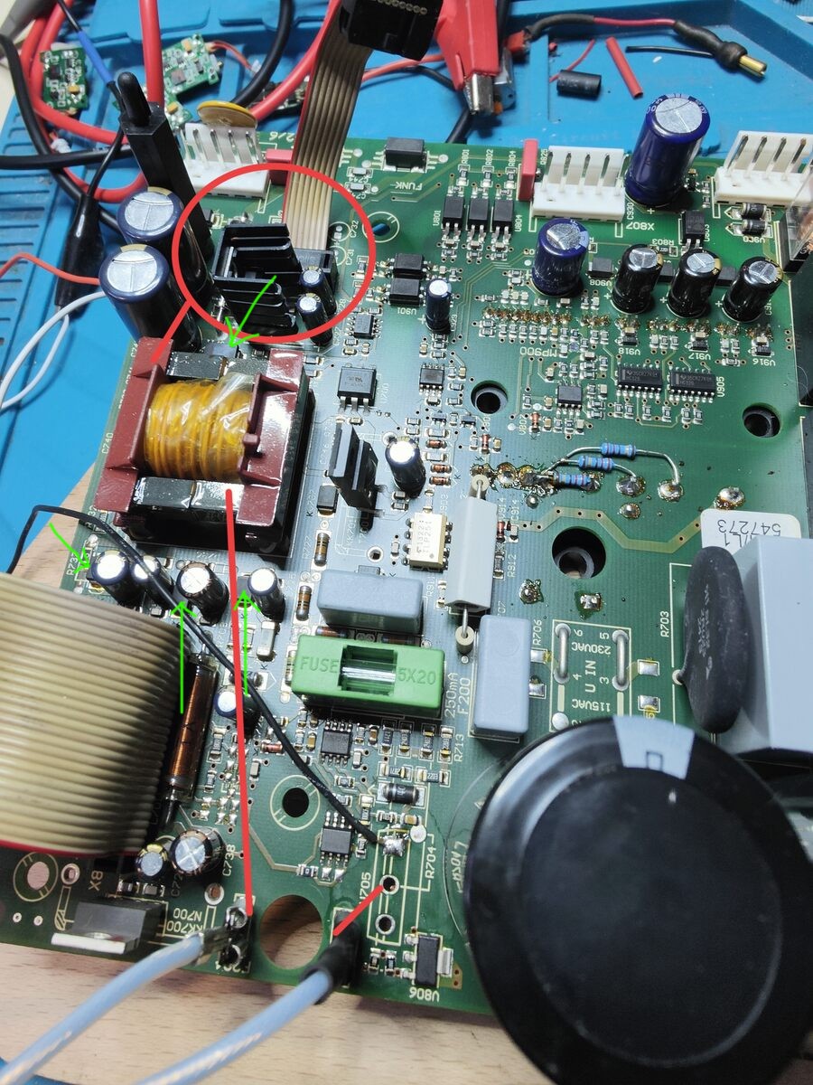
, R94, R95, R96, R97, R98, R99, R100, R101, R102, R103, R104, R105, R106, R107, R108, R109, R110, R111, R112, R113, R114, R115, R116, R117, R118, R119, R120, R121, R122, R123, R124, R125, R126, R127, R128, R129, R130, R131, R132, R133, R134, R135, R136, R137, R138, R139, R140, R141, R142, R143, R144,
-
 Bild
Bild
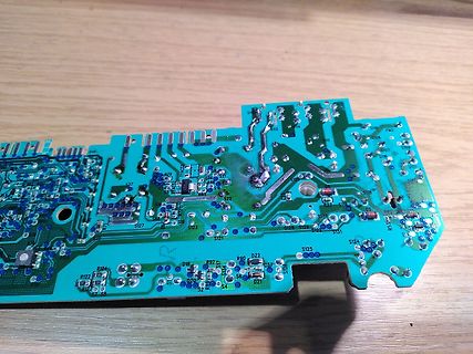
Foto einer grünen Leiterplatte
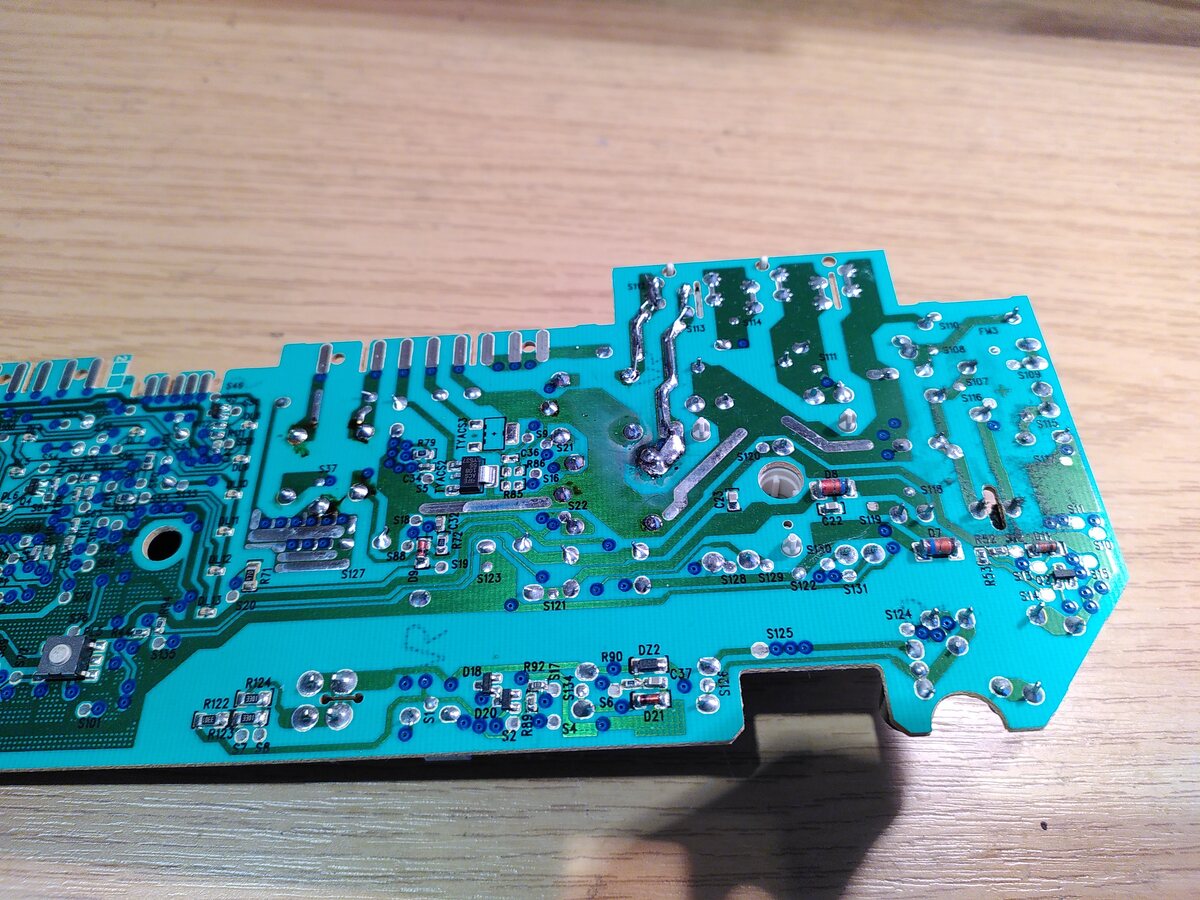
S125, S126, S124, S128, S131, R53, R54, S116, S117, S118, S119, S120, S113, FM3, S115, S114, S112, S111, S110, S109, S108, S107, S106, S105, S104, S103, S102, S101, S100, S99, S98, S97, S96, S95, S94, S93, S92, S91, S90, S89, S88, S87, S86, S85, S84, S83, S82, S81, S80, S79, S78, S77, S76, S75, S74, S73
-
 Bild
Bild
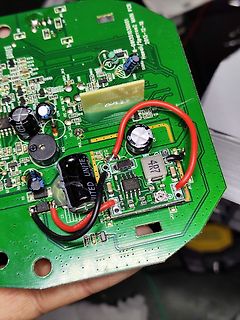
Grüne Leiterplatte mit Bauteilen und roten Kabeln
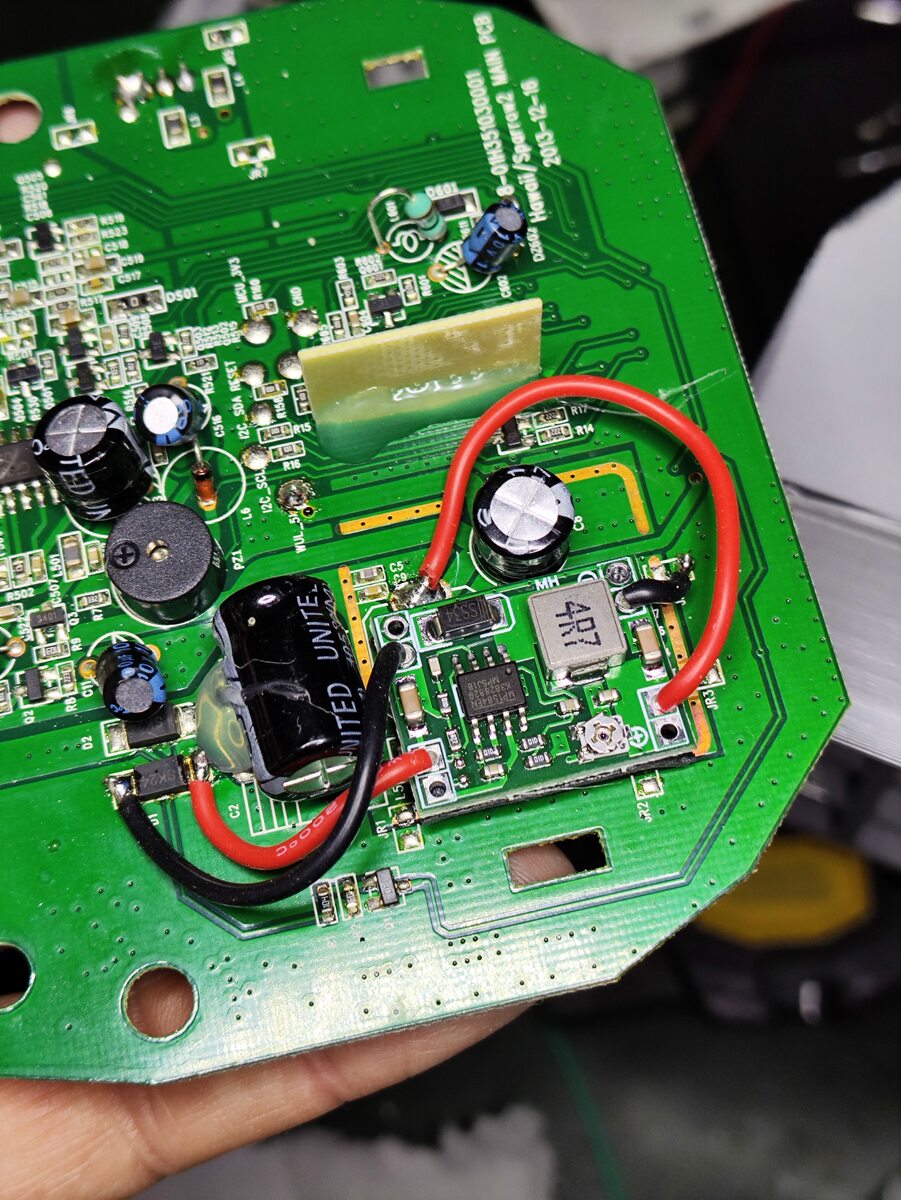
, C94, C95, C96, C97, C98, C99, C100, C101, C102, C103, C104, C105, C106, C107, C108, C109, C110, C111, C112, C113, C114, C115, C116, C117, C118, C119, C120, C121, C122, C123, C124, C125, C126, C127, C128, C129, C130, C131, C132, C133, C134, C135, C136, C137, C138, C139, C140, C141, C142, C143, C144,
-
 Bild
Bild
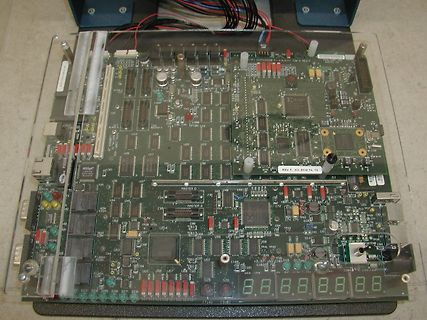
Bestückte Leiterplatte mit Display und Anschlüssen
, U94, U95, U96, U97, U98, U99, U100, U101, U102, U103, U104, U105, U106, U107, U108, U109, U110, U111, U112, U113, U114, U115, U116, U117, U118, U119, U120, U121, U122, U123, U124, U125, U126, U127, U128, U129, U130, U131, U132, U133, U134, U135
-
 Bild
Bild
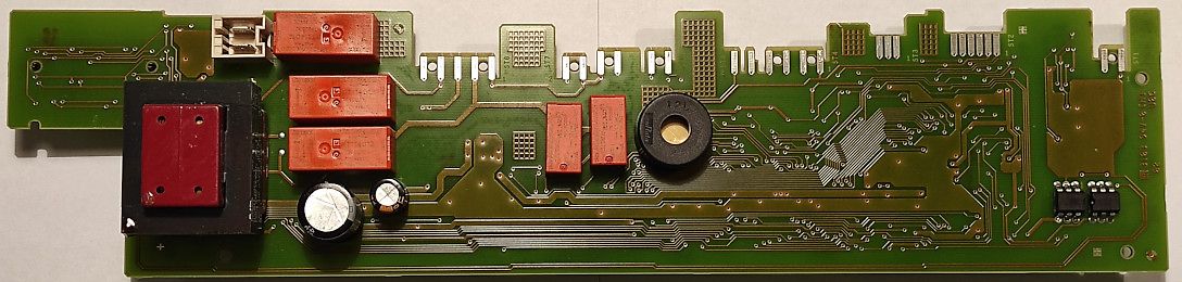
Foto einer bestückten Leiterplatte
, L94, L95, L96, L97, L98, L99, L100, L101, L102, L103, L104, L105, L106, L107, L108, L109, L110, L111, L112, L113, L114, L115, L116, L117, L118, L119, L120, L121, L122, L123, L124, L125, L126, L127, L128, L129, L130, L131, L132, L133, L134, L135, L136, L13
-
Thread
Einrichtung Yubikey auf Debian: Erfahrung/Tipps
per Shell bedienbar sein - leider unübersichtlich). 2. GUI AppImage von yubico.com heruntergeladen: 111 MB: bietet nur Ein/Ausschalten von USB/NFC und Eingabe für die PIN. PIN eingegeben. 3. Seite des RZ zur Einrichtung anklicken: man wird nach der PIN gefragt und muss dann den Key drücken (analog zum
-
Thread
ESP32: komisches Verhalten
heap_init: At 3FFE0440 len 00003AE0 (14 KiB): D/IRAM I (262) heap_init: At 3FFE4350 len 0001BCB0 (111 KiB): D/IRAM I (268) heap_init: At 4008B194 len 00014E6C (83 KiB): IRAM I (276) spi_flash: detected chip: generic I (279) spi_flash: flash io: dio W (283) spi_flash: Detected size(4096k) larger
-
 Bild
Bild
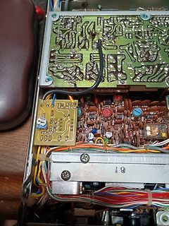
Innenansicht eines geöffneten elektronischen Geräts mit Leiterplatten
, R94, R95, R96, R97, R98, R99, R100, R101, R102, R103, R104, R105, R106, R107, R108, R109, R110, R111, R112, R113, R114, R115, R116, R117, R118, R119, R120, R121, R122, R123, R124, R125, R126, R127, R128, R129, R130, R131, R132, R133, R134, R135, R136, R137, R138, R139, R140, R141, R142, R143, R144,
-
 Bild
Bild
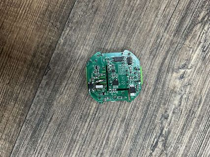
Grüne Leiterplatte auf Holzuntergrund
, R94, R95, R96, R97, R98, R99, R100, R101, R102, R103, R104, R105, R106, R107, R108, R109, R110, R111, R112, R113, R114, R115, R116, R117, R118, R119, R120, R121, R122, R123, R124, R125, R126, R127, R128, R129, R130, R131, R132, R133, R134, R
-
 Bild
Bild
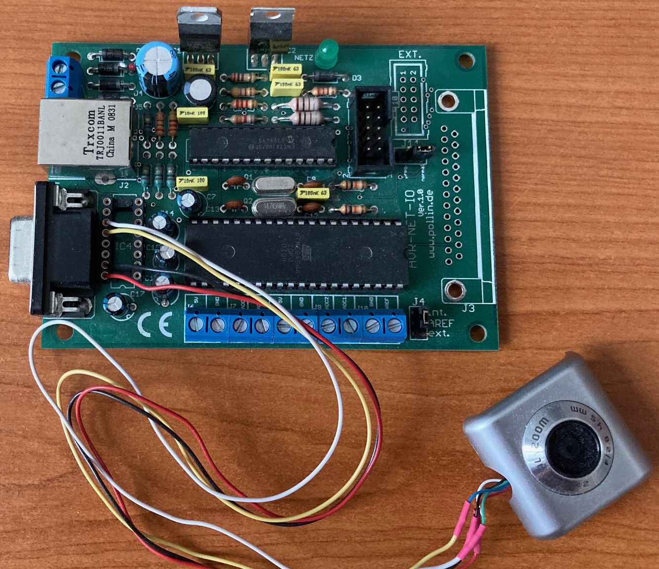
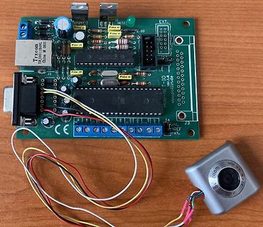
Bestückte Leiterplatte mit Kameraeinheit und Kabeln
J2 J4 J3 Trxcom China M 0831 AVR-NET ver.1.0 www.pollin.de 101 102 103 104 105 106 107 108 109 110 111 112 113 114 115 116 117 118 119 120 121 122 123 124 125 126 127 128 129 130 131 132 133 134 135 136 137 138 139 140 141 142 143 144 145 146 147 148 149 150 151 152 153 154 155 156 157 158 159 160 161
-
 Bild
Bild
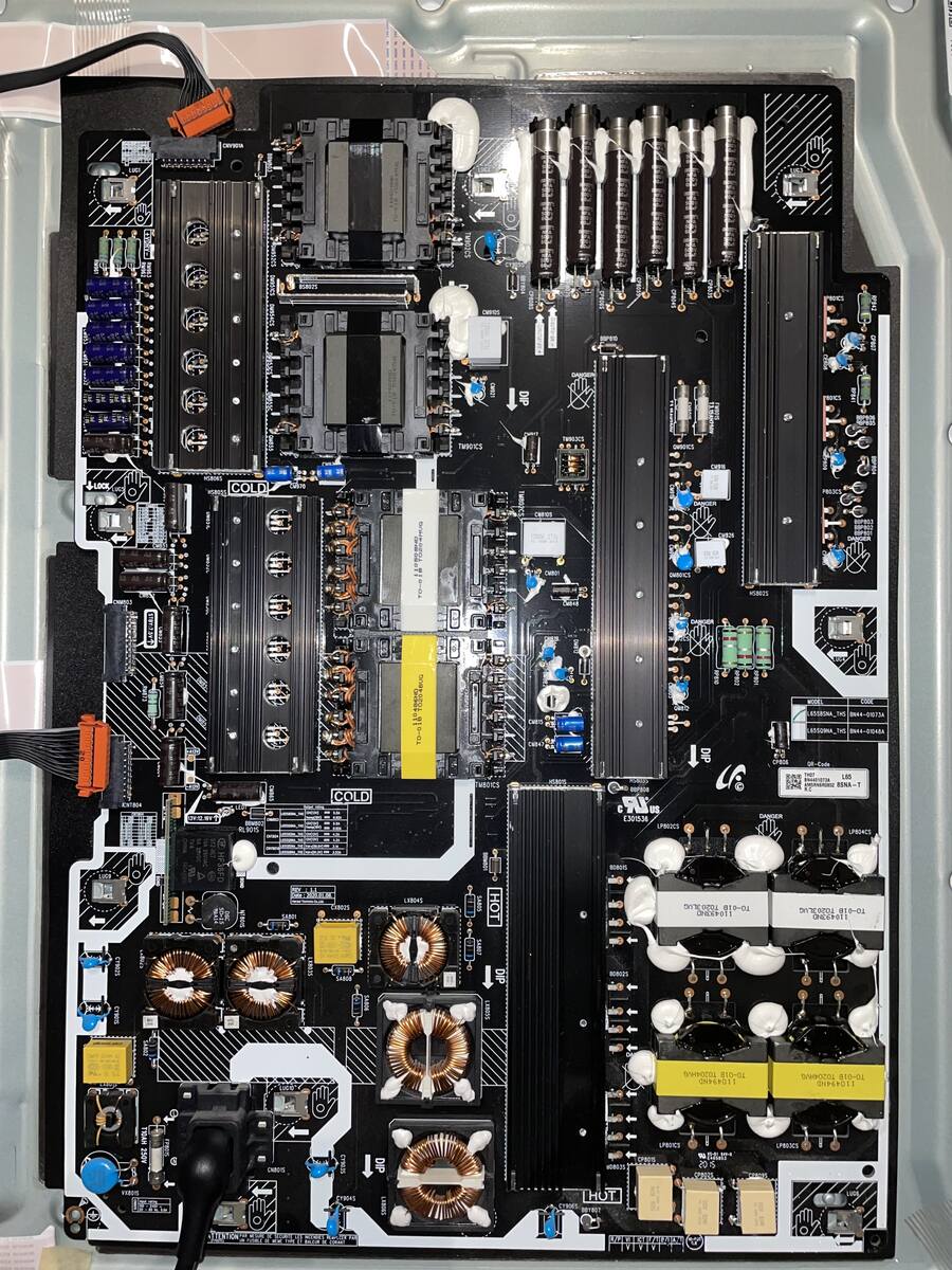
Leiterplatte eines Netzteils mit Kühlkörpern und Spulen
, L94, L95, L96, L97, L98, L99, L100, L101, L102, L103, L104, L105, L106, L107, L108, L109, L110, L111, L112, L113, L114, L115, L116, L117, L118, L119, L120, L121, L122, L123, L124, L125, L126, L127, L128, L129, L130, L131, L132, L133, L134