NOTICE. THE PRODUCTS DESCRIBED HEREIN AND THIS DOCUMENT ARE SUBJECT TO SPECIFIC DISCLAIMERS, SET FORTH AT www.vishay.com/doc?91000 OLED-128O064D-BPP3N00000 www.vishay.com Vishay INTERFACE PIN FUNCTION PIN NO. SYMBOL FUNCTION Reserved pin (supporting pin) 1 NC (GND) The supporting pins can reduce the influences
at SDIN 15 D/C# I will be interpreted as data.When it is 2ulled low, the data at SDIN will be transferred to the command register.In I C mode, this pin acts as SA0 for slave address selection. For detail
data bit has some limitations. 1. The data bit, which is transmitted during each SCL pulse, must keep at a stable state within the “HIGH” period of the clock pulse. Please refer to the Figure 8-10 for graphical representations. Except in start or stop conditions, the data line can be switched only when
to row address 00h) 4. Shift register data clear in serial interface 5. Display start line is set at display RAM address 0 6. Column address counter is set at 0 7. Normal scan direction of the COM outputs 8. Contrast control register is set at 7Fh 9. Normal display mode (Equivalent to A4h command) http
Electrical Characteristics”. If this module is used beyond these conditions, malfunctioning of the module can occur and the reliability of the module may deteriorate ELECTRICAL CHARACTERISTICS STANDARD VALUE ITEM SYMBOL CONDITION UNIT MIN. TYP. MAX. Supply voltage for logic VDD - 2.8 3.0 3.3 Supply voltage
inputs. H A variable gain control input which linearly adjusts the overall gain. The gain is zero at –1 V and maximum at +1 V. H Three separate differential outputs that can be turned on or off using the output enable control signals (out1en, out2en, out3en). The inv controls are left at 0. Table 1–
http://exploreembedded.com/wiki/images/1/1a/Progisp1.72.rar [/code] 3. damit konnte ich den MC AT90S8515 programmieren Das RESET-Signal vom USBASP ist mit dem RESET-Signal vom MC verbunden. Interner Takt (Quarz 4Mhz) 4. den MC AT89S52 konnte ich nicht programmieren Das RESET-Signal vom MC ist
Hallo, mit dem richtigen Hex-File für den MC AT89S51/52 kann ich die MC's mit dem Programm PROGISP programmieren (mit Fortschrittsbalken). Mein Fehler: ich hatte zum Test den Hex-File für den MC AT90S8515 verwendet. Vielen Dank für Eure Hilfe.
//www.i-core. cnO.777,JianP.C.:214072nhu District,Wuxi City,Jiangsu PVER:2024-01-B15 The key press can only be identified only when it lasts two key scan periods at least.50E-AX-XS-B037EN as follows:tion application, the block processing between KI1 and KI2 with key combination function isd at the e
may cause permanent damage to the device. These are stress ratings only and operation of the device at these or at any other conditions above those given in the Characteristics sections of the specification is not implied. Exposure to limiting values for extended periods may affect device reliability.
differ in case of multiple devices. The latest product status information is available on the Internet at URL http://www.nxp.com. 11.2 Definitions malfunction of a NXP Semiconductors product can reasonably be expected to result in personal injury, death or severe property or environmental damage. NXP Semiconductors
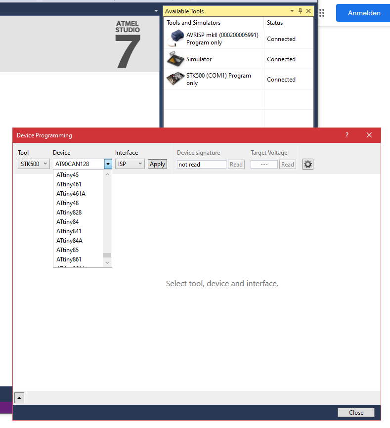
entspricht AVR Simulator 2 in 4.19), somit kann man ältere, aber noch immer aktuelle Mikrocontroller wie AT90CAN128 u.Ä. nur mit Studio 4 simulieren. P.S. statt WinAVR Version 20100110 benutze ich "per Hand" aus Atmel Studio herausgenommene spätere GNU Compiler-Version. Das bringt einige Vorteile, z.B.
information is provided with front panel LEDs, logic 2 signals and IC management interface.Three units can be packaged into an optional 19" 1U power shelf to provide up to 8.4kW of power. FEATURES SELECTION GUIDE Power Output Main Standby Current n RoHS compliant Part Number High Line AC Output Output Airflow
should match the PWM duty cycle within ±10%. If no control signal is present the fan shall operate at maximum RPM. See Figure 3. Figure 3 Fan Speed Response to PWM Control Input Signal Speed vs. PWM Duty cycle %of full speed Max. 100 PWM 90 Max. 80 RPM 70 60 Min. PWM 50 40 30 Minimum specified RPM must
, and the system clock can be divided by set- ting the “Clock Prescale Register – CLKPR” on page 35. This feature can be used to decrease 34 AT90USB82/162 7707F–AVR–11/10 AT90USB82/162 the system clock frequency and the power
Return flow safety device If the liquid levels in the circulator bath and the external system are at different heights, overflowing must be prevented after the power has been turned off. Flood hazard! For this reason, solenoid valves for loop circuit or shut-off valves can be integrated in the loop
circuit of automotives, and have releasecapabiliandhhighereliabiliforhigh has high heat bridge circuit can be configured easily in small area by :(2) polarity type.S” type and suffix “R” type of reverse (1) n s Features s i(1) 72) , ● Thermal Fatigue Capability: 5,000 cyc.h Reliability SDffix “S”Z 2 7 S
different frequencies are mixed to form DTMF tones. Figure 1. DTMF Generator V CC VCC PD5 GND AVR AT90S4414 PB4 1 2 3 A PB7 4 5 6 B PB5 7 8 9 C PB6 PB0 PB7 * 0 # D GND P P P P 0 1 2 3 GND XTAL1 XTAL2 8 MHz 22 pF 22 pF GND GND Rev. 1982B–AVR–05/02 1 Table 1. DTMF Tone Matrix fb/fa 1209 Hz 1336 Hz 1477
electrolytic capacitors, switching current, it requires an adequate ripple the ESR dominates the impedance at the current rating. The RMS current in the input switching frequency. For simplification, the capacitor can be estimated by: output ripple can be approximated to: VOUT ⎜ VOUT ⎟ ∆V = VOUT ×⎛1− VOUT ⎞×
circuitry Choose an inductor that will not saturate under the maximum inductor peak current. The peak can be seen at the output when the MP1584 is at no load. In order to absorb this small amount inductor current can be calculated by: of current, keep R2 under 40KΩ. A typical value for R2 can be 40.2kΩ.
turn-on of the diac can be varied by modifying the to the lamp can be varied, thus dimming control time constant of the RC network formed by R and can be added; Figure 1. Electronic transformer for 12V Halogen Lamp R C2 T'
secrets, and other intellectual property. A listing of onsemi’s product/patent coverage may be accessed at www.onsemi.com/site/pdf/Patent−Marking.pdf. onsemi reserves the right to make changes at any time to any products or information herein, without notice. The information herein is provided “as−is” and
40 50 0 0 0 50 100 150 200 0 25 50 75 100 125 150 175 200 T (°C) Tmb (°C) mb V ≥ 10 V GS (1) Capped at 120A due to package Fig. 2. Continuous drain current as a function of Fig. 1. Normalized total power dissipation as a function of mounting base temperature mounting base temperature 3 aaa-028222 10 D
etwas schwieriger zu löten, geht aber auch... Diese zwei Typen würde ich für alles empfehlen. Für CAN noch AT90CAN128, aber man kann auch ohne, mit einem externen CAN-Controller alles machen. Aber 8-Füßler - wozu?
wave response will exhibit ringing if the capacitance is greater than about 0.1 μF. The amplifier can typically drive load capacitances up to 2 μF or so without oscillating, but this is not recommended. If highly capacitive loads are expected, a resistor (at least 1Ω) should be placed in series with the output of the LM675. A method commonly employed to protect amplifiers from low impedances at high frequencies is to couple to the load through a 10Ω resistor in parallel with a 5 μH inductor. CURRENT LIMIT AND SAFE OPERATING AREA (SOA) PROTECTION A power amplifier's output transistors can be
Guide Section 3.1 // Addresses defined as offsets from the base address called RAM_REG and located at 0x302000 // Discussion: Defining this way leads to an additional add operation in code that can be avoided by defining // these addresses as 32 bit values, but this is easily paid for in clarity and
measure the frequency of a rectangular signal using an Atmega328P microcontroller in C programming, you can utilize one of the hardware timers available on the chip. The frequency measurement can be done by counting the number of rising or falling edges of the signal within a specific time period. Since
Downloads/ACS712-Datasheet-1.pdf): "The thickness of the copper conductor allows survival of the device at up to 5× overcurrent conditions.the device at up to 5× overcurrent conditions." ... das ist doch schon mal was ... Und dann noch das hier im Abschnitt "Absolute maximum Ratings": "Overcurrent
32bit with Float Number. Only after falling below or exceeding the preset value in the hysteresis (at the lower / upper trigger limit) the trigger is actuated. (Thus, it can be avoided that the trigger is permanently actuated when the values fluctuate around the preset upper or lower trigger limit.)
das nicht kommerziell nutzt wird's wohl keinen interessieren. Vielleicht reich ja für's erste die 90 Tage Testversion. Danach kannst Du ja immer noch entscheiden wie Du weiter machst. In DE gibt es auch einen Händler (https://www.flexicad.com/rhino8.htm).
ich damit die erstellten Modelle ind DXF, STP oder C4D exportieren? The current OpenSCAD model can be export in different formats. The list of supported formats depends on the geometry, if the final design is a 3D or 2D model. OpenSCAD can export 3D formats STL (ASCII only) OFF
is Time B, the time period from Time A through Time B. 2. In the case of CMOS Output: When the time at which a pulse voltage which increases from 1.2V to +V DET +2.0V is applied to VDD is Time A, and the time at which the output voltage reaches the voltage of (+V DET+2.0V)/2 is Time B, the time period
Guide Section 3.1 // Addresses defined as offsets from the base address called RAM_REG and located at 0x302000 // Discussion: Defining this way leads to an additional add operation in code that can be avoided by defining // these addresses as 32 bit values, but this is easily paid for in clarity and
the values assigned by commands BITMAP_TRANSFORM_A-F. 2.10.6 Color and Transparency The same bitmap can be drawn in more places on the screen, in different colors and transparency: dl(COLOR_RGB(255, 64, 64)); // red at (200, 120) dl(VERTEX2II(200, 120, 0, 0)); dl(COLOR_RGB(64, 180, 64)); // green at (
transactions, the host sends a ‘0’ bit and ‘1rdbit, followed by the 6-bit command code. The 2 byte can be either 00h, or the parameter of that commandbyte is fixed at 00h. All SPI commands except the system reset can only be executed when the SPI is in the Single channel mode. They will be ignored when
’ve been producing 70,000 units a week for the last few weeks, and this rate is set to increase to 90,000 units a week by the end of January. [/c] ### Raspberry Pi: optimierter TFLite-Port für den RP2040. Eine „grundlegende“ Portierung der Embedded-ML-Bibliothek TFLite für den RP 2040 geistert
, this series provides two sets of power supply IOs (VDDIO supply pins), each capable of operating at different voltage ranges, making it more adaptable to various external device voltage standards and seamlessly integrating into multiple applications. [/c]
Maximum power dissipation is a function of T (ma, and T . The maximum allowable power dissipation at any allowable J JA A ambient temperature iD P =J(T (max)A– JA. Operating at the absolute maximJm T of 150⋅C can impact reliability. 4. The package thermal impedance is calculated in accordance with JESD
zwar 0,5 mm Pinabstand, aber notfalls geht das auch... Und meine Lieblinge ATMega1284(P) und auch AT90CAN128 kann ich wie früher mit Atmel AVR JTAGICE mkII bedienen: entweder aus Win11 über USB/RS232 Converter oder aus Win7 über USB mit dem älteren Notebook, da ich AVR Studio 4.19 einfach mag.
> 0,5 mm Pinabstand, aber notfalls geht das auch... Und meine Lieblinge > ATMega1284(P) und auch AT90CAN128 kann ich wie früher mit Atmel AVR > JTAGICE mkII bedienen: entweder aus Win11 über USB/RS232 Converter oder > aus Win7 über USB mit dem älteren Notebook, da ich AVR Studio 4.19 > einfach mag
washing process; in this case the requirements 1 with respect to clearances and creepage distances can change. curve 3: maximum voltage at contact current = 0 A curve 4: limiting voltage U 2 at rated contact current Irated recommended voltage range (shaded area): RT IV: sealed relay the coil voltage
kleinen Streich erinnert, den wir vor einigen Jahren unseren Kollegen gespielt haben. Ein kleiner AT90USB162 wurde dazu mit der LUFA-Bibliothek von Dean Camera (Four Walled Cubicle) so programmiert, daß er sich beim Rechner als HID-Tastatur und -Maus angemeldet, und zufällig "eine Taste gedrückt" oder
warten, um offiziellen USB-Support zu bekommen. Wirklich relevant wurde USB ohnehin erst Ende der 90er ("Useless Serial Bus").
>> block.3: cdrom ----- /proc/sys/dev/cdrom/info ----- drive name: drive speed: drive # of slots: Can close tray: Can open tray: Can lock tray: Can change speed: Can select disk: Can read multisession: Can read MCN: Reports media changed: Can play audio: Can write CD-R: Can write CD-RW: Can read DVD
after entering fast decay mode, until the blanking time has expired. To provide better current control at very low current steps, an adaptive blanking time mode can be enabled by setting the ABT bit in the BLANK register. If ABT is set, at current levels below 30% of full scale current (as determined by
and button for 3 seconds: MENU, Button the message “CONTROLS LOCKED” appears. CONTROLS LOCKED You can unlock the OSD controls at any time by pushing the MENU, button for 3 seconds: the message “CONTROLS UNLOCKED” will appear. CONTROLS UNLOCKED Headphone jack that automatically mutes the speaker volume
Moisture Sensitivity Level D-PAK ††† (per JEDECJ-ST D-020D ) RoHS compliant Yes Qualification standards can be found at International Rectifier’s web site http://www.irf.com/product-info/reliability Higher qualification ratings may be available should the user have such requirements. Please contact your International
reference of 2.5 V has an enhanced design and utilizes production trim to allow initial accuracy of ±1% at room temperature and ± 2% over the full temperature range. This can be used to eliminate an external reference in applications that do not require the extreme accuracy afforded by the additional device
probieren wo es klemmt. Leider gibt's keine Richtwerte dazu, manche Pipetten sind locker bei 250 wo es 90 brauchen brauchen würde, manche schaffen neu und frisch gewartet die 90 Soll-mbar so gerade eben, je nach Größe.
anfahren sind jeweils 2 Befehle. > > Bei Siplace reichlich sicher nicht. Da geht sooo viel über den CAN-Bus. Na dann einfach CAN Bus mitschneiden. Und crashen wird eine Maschine mit Absolutkoordinaten-Steuerung sehr wahrscheinlich nicht sofern die Nozzle nicht unten hängt. So verrückt und mit einer
or effectiveness. provided in the labeling, can be reasonably expected to result in significant injury to the user. PRODUCT STATUS DEFINITIONS Definition of Terms Datasheet Identification Product Status Definition Advance Information Formative or
its value after the commit transaction command. Several files can be changed within an application at the same time. The abort transactions command annulates all changes within an application. Power loss will cancel all modifications too. For more details about the
needs an external application specific antenna to operate. By using the serial interface the device can be connected to a controller or any host system easily. The small form factor enables a design in even into very compact systems. Typical Applications • e-Payment • Access Control • e-Toll Road Pricing
übers UDS Protokoll von einem bestimmten Steuergerät abfragen und ändern. Das Steuergerät hat die Can ID 1546 für requests und 1153 für responses. ich versuche also mit AT SH 48 1546 F1 den Header zu setzen und kriege auch eine OK antwort. auch wenn ich nun 3E 00 für tester present wird beantwortet
interessant gesehen, geht es zufällig um einen neueren BMW? BMW macht in den neueren Modellen über CAN CEA, d.h CAN Extended Adressing. Das muss man entsprechend im Adapter konfigurieren, sonst kommt der damit nicht zurecht.

 Bild
Bild