-
Thread
OrangePi 4 Pro / OrangePi 6 Plus – Einplatinencomputer im Zeichen der Leistung
wiringPiSetup(); gpio_num = i =0; pinMode (i, OUTPUT) ; for ( ;; ) { digitalWrite (i, HIGH); // On digitalWrite (i, LOW); // Off } return 0; } [/c] Lohn der Mühen ist das in der Abbildung gezeigte Schirmbild. 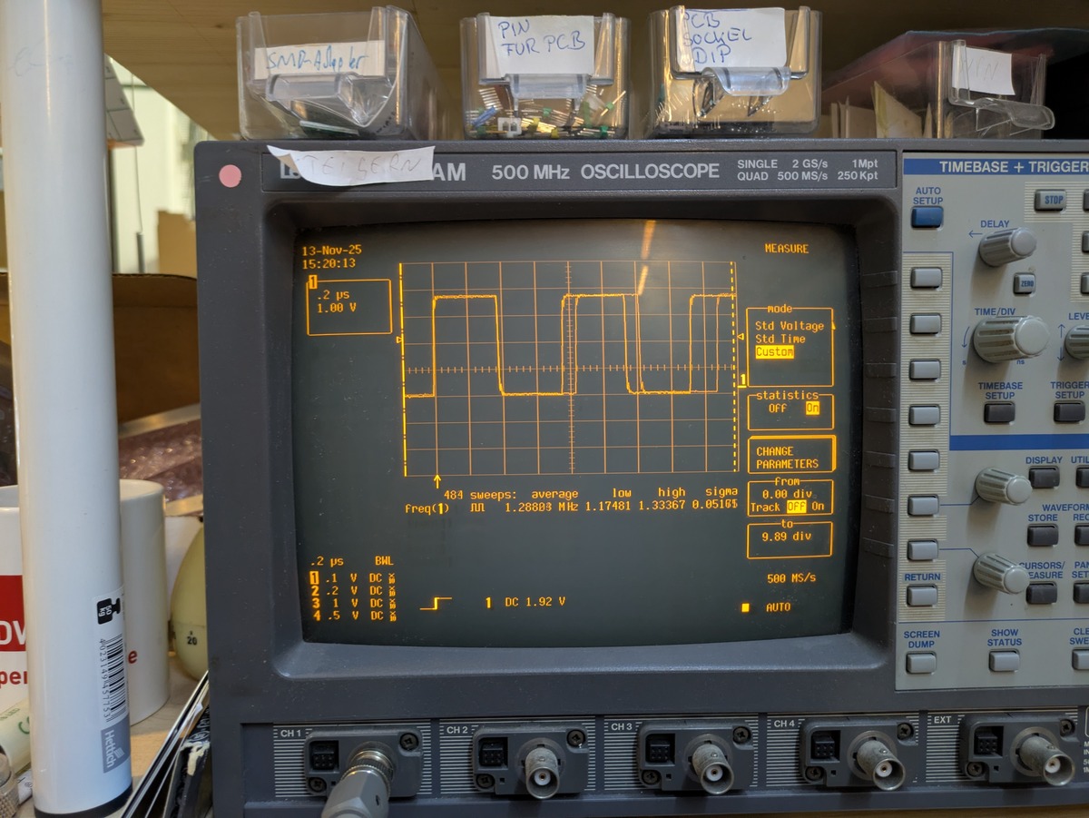 Zu beachten ist, dass
-
 Bild
Bild
Oszilloskop mit Rechtecksignal auf Display
13 MEASURE mode Std Voltage Std Time Custom statistics Off ON CHANGE PARAMETERS 484 sweeps: average low high sigma -From 0.00 div 2 µs BWL Freq? JUL 1.28883 1.17401 1.33367 0.0516 9.89 div 2 µs V DC 1 DC 1.92 V 4.5 V DC CH 1 CH 2 CH 3 CH 4 EXT
-
 Bild
Bild
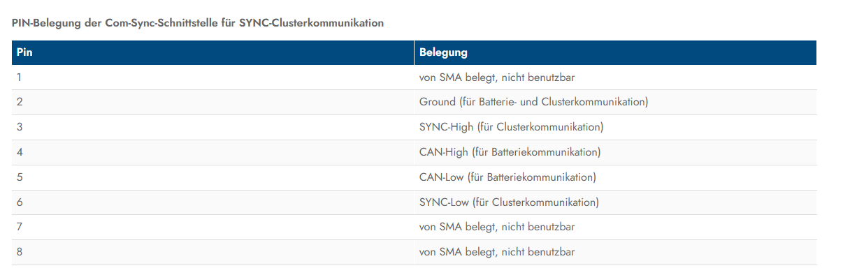
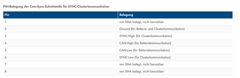
Tabelle der Pin-Belegung einer Com-Sync-Schnittstelle
1 | von SMA belegt, nicht benutzbar 2 | Ground (für Batterie- und Clusterkommunikation) 3 | SYNC-High (für Clusterkommunikation) 4 | CAN-High (für Batteriekommunikation) 5 | CAN-Low (für Batteriekommunikation) 6 | SYNC-Low (für Clusterkommunikation) 7 | von SMA belegt, nicht benutzbar 8 | von SMA belegt
-
Thread
UND Schaltung einer 5V Spule
Die Sensoren werden vom selben 5V DC Netzteil betrieben, sind als Taster konfiguriert, geben ein HIGH Signal aus und haben einen maximalen Schaltstrom von 8mA. Die Spulen ziehen dauerhaft 3,6A, der Anlaufstrom wird demnach höher ausfallen. Hier liegt die erste Hürde. Auf der Suche nach einer Lösung
Einen Touch-Sensor konfigurierst Du auf "Active-High", den anderen auf "Active-Low". Dann nimmst Du folgende Platine von Amazon: https://www.amazon.de/JZK-Elektronische-Schaltsteuerplatine-Pulsausl%C3%B6ser-Schaltermodul-MOSFETs-Optokoppler/dp/B09SWRF88D
-
 Bild
Bild
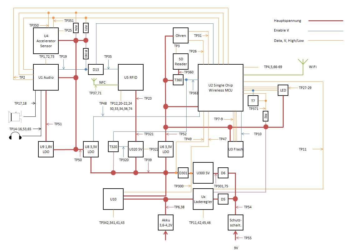
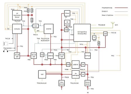
Blockschaltbild eines elektronischen Geräts mit Mikrocontroller und WiFi
TP351, Hauptspannung, Enable V, TP25, R24, R23, TP3, Ohren, TP31, Data, V, High/Low, TP2, U1 Audio, U4 Accelerator Sensor, TP1,72,73, TP19, TP35, D13, NFC, U5 RFID, TP37,71, TP23, TP48, TP12,20,22,24, 30,33,34,36,74, T360, TP361, U2 Single Chip Wireless MCU, TP4,5,66-69, WiFi,
-
Thread
24 Volt relais treiber
Kommunikationsfehlern. Auch wenn bei der Datenübertragung primär die Spannungsdifferenz zwischen den Leitungen (CAN High und CAN Low) genutzt wird, dient die Masse als Referenzpunkt für die Spannungen. "
-
 Bild
Bild
Produktseite eines 12V 1-Kanal Relaismoduls
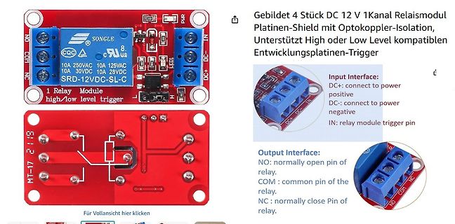
Gebildet 4 Stück DC 12 V 1Kanal Relaismodul Platinen-Shield mit Optokoppler-Isolation, Unterstützt High oder Low Level kompatiblen Entwicklungsplatinen-Trigger SONGLE 10A 250VAC 10A 125VAC 10A 30VDC 10A 28VDC SRD-12VDC-SL-C NO COM NC IN DC+ DC- LED1 LED2 Input Interface: DC+: connect to power positive
-
Thread
Arduino Nesso N1, IDE-Updates, Quartalszahlen und Politik
, they are designed to offer the industry’s most balanced RF compute fabric, capable of balancing high throughput, lower power compute with the flexibility engineers demand. [/c] Für die Basisversion VR1602 gilt, dass AMD schon jetzt erste Samples verteilt – weitere Informationen finden sich unter
bring their own models and deploy them efficiently across ADI’s processors and microcontrollers, from low-power edge devices to high-performance DSPs (digital signal processors). The latest platform, based on Microsoft’s Visual Studio Code, features a built-in model compatibility checker, performance profiling
-
Thread
Taster Öffner zu Schließer (3D Taster)
auseinander. Ich dachte anfangs das ich sowas nehme und so anschließe.: Bei NPN LOF bzw. BEI PNP High NPN-Variante (LOW-Trigger): Braun → DC+, Blau → DC−, Weiß → DC−, Grün → IN, Jumper/Schalter auf LOW. Ausgang zur Steuerung: COM + NO ⇒ potenzial schliesser den ich brauche. https://www.amazon.de
-
Thread
Frequenzanzeige aus Eingangssignal generieren.
Marcel V. schrieb im Beitrag #7965045: > Exakt Ich seh da keinen Ausgang high bei f1<f2 und low bei f1>f2
Michael B. schrieb im Beitrag #7965151: > Ich seh da keinen Ausgang high bei f1<f2 und low bei f1>f2 Dafür sehe ich sogar zwei Ausgänge, die genau das machen, Pin 2 und Pin 13!
-
Thread
ESP32-C6 an 18650 Akku betreiben
doch sowieso dein eigenes Shield bauen? Olli Z. schrieb im Beitrag #7964085: > Ich plane einen Low-Power Shield Ansonsten gibt es noch jede Menge weitere effiziente Schaltregler... Da muss man wohl etwas Bauteilrecherche betreiben
Leveraging Power Consumption: Offers four working modes, including a deep sleep mode with consumption as low as 15 μA, along with support for lithium battery charge management." https://wiki.seeedstudio.com/xiao_esp32c6_getting_started/
-
 Bild
Bild
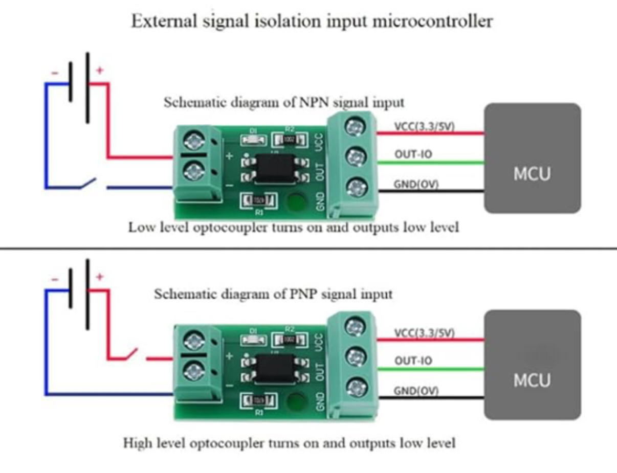
Blockschaltbild NPN und PNP Signal Isolation Input
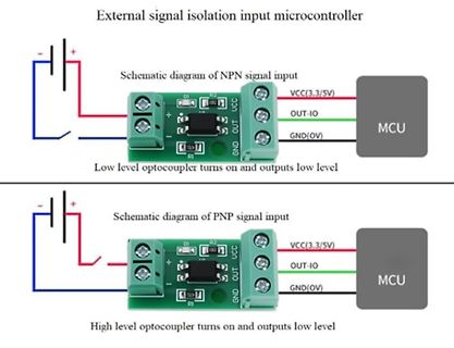
microcontroller Schematic diagram of NPN signal input DI R2 VCC(3.3/5V) + - OUT-IO MCU R1 GND(0V) Low level optocoupler turns on and outputs low level Schematic diagram of PNP signal input High level optocoupler turns on and outputs low level
-
 Bild
Bild
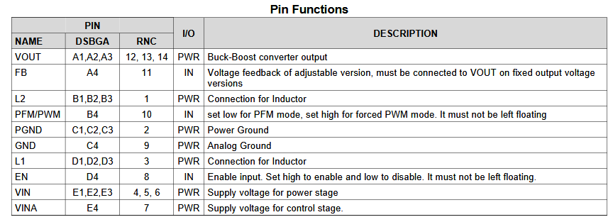
Pin-Funktionstabelle eines ICs
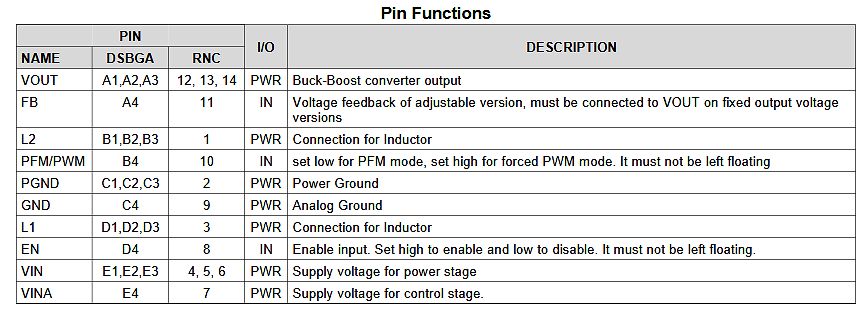
VOUT on fixed output voltage versions L2 B1,B2,B3 1 PWR Connection for Inductor PFM/PWM B4 10 IN set low for PFM mode, set high for forced PWM mode. It must not be left floating PGND C1,C2,C3 2 PWR Power Ground GND C4 9 PWR Analog Ground L1 D1,D2,D3 3 PWR Connection for Inductor EN D4 8 IN Enable input. Set high to enable and low to disable. It must not be left floating. VIN E1,E2,E3 4, 5, 6 PWR Supply voltage for power stage VINA E4 7 PWR Supply voltage for control stage.
-
 Bild
Bild
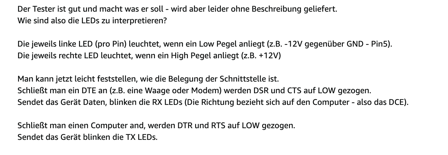
Anleitung zur Interpretation von LED-Statusanzeigen eines Testers
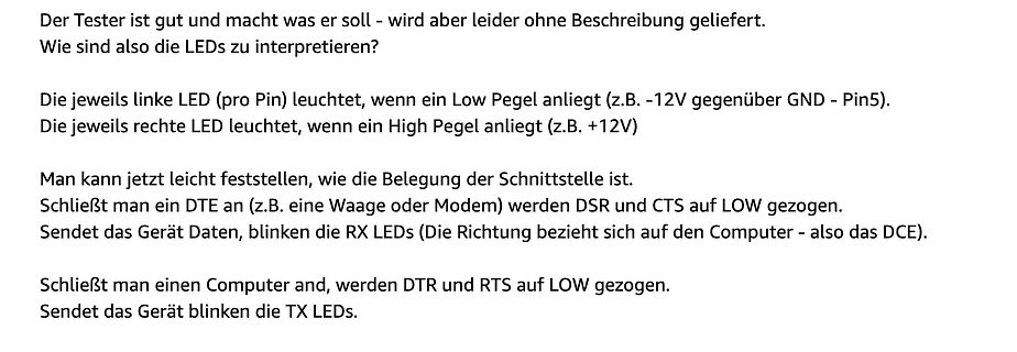
geliefert. Wie sind also die LEDs zu interpretieren? Die jeweils linke LED (pro Pin) leuchtet, wenn ein Low Pegel anliegt (z.B. -12V gegenüber GND - Pin5). Die jeweils rechte LED leuchtet, wenn ein High Pegel anliegt (z.B. +12V) Man kann jetzt leicht feststellen, wie die Belegung der Schnittstelle ist. Schließt man ein DTE an (z.B. eine Waage oder Modem) werden DSR und CTS auf LOW gezogen. Sendet das Gerät Daten, blinken die RX LEDs (Die Richtung bezieht sich auf den Computer - also das DCE). Schließt man einen Computer and, werden DTR und RTS auf LOW gezogen. Sendet das Gerät
-
Thread
Steuersignale "morsen" oder wie bei "Impulswahl" übertragen.
versuchen: [c] /* * Pulswahl ähnlicher Sender für Relais * */ #define PULSPIN 13 #define HIGH_MS 200 #define LOW_MS 100 #define PAUSE_MS 100 #define END_MS 300 // adr=0..63, cmd=0..3 void send(uint8_t adr,uint8_t cmd) { uint8_t val=(adr<<2) + (cmd&0x0F); for(int n=0;n<8;n++) { digitalWrite(PULSPIN,HIGH); if(val&0x80) delay(HIGH_MS); else delay(LOW_MS); digitalWrite(PULSPIN,LOW); delay(PAUSE_MS); val=val<<1; } delay(END_MS); } void setup() { pinMode
-
Thread
Si5351 Generator, ESD Schutz
in dem Schaltplan so aus. Im DaBla wird ein 25- oder 27-MHz-Quarz (!) verlangt. "Operates from a low-cost, fixed frequency crystal: 25 or 27 MHz" Nebenbei: lt. Hans Rosenberg ist es prinzipiell besser, mehrere 100nF-Cs parallel zu schalten als unterschiedlich große parallele Abblock-Cs zu verwenden
unmerklich in die "Höhe" und haben dann keinen Kontakt mehr. Ansonsten sollten für die alle USB high-speed dioden passen (also 480mbit). Eine SRV05-4 hätte z.B 4 Kanäle und sollte mit <4pF noch verträglich sein. Einzeldioden bekommst recht leicht mit <1pF. Übrigens ist so ein -6dB Dämpfer am
-
Thread
Skyworks kauft Qorvo, Neues von Nexperia und andere Lustigkeiten
transaction that values the combined enterprise at approximately 2 to create a -based, global leader in high-performance radio frequency (RF), analog and mixed-signal semiconductors. [/c] Wer selbst Aktien an einer der beiden Firmen hält (Qorvo derzeit bei 94USD, Skyworks bei 76USD), muss folgendes beachten
with its resistance to Single-Event Effects (SEE) and Total Ionizing Dose (TID). It also features low power management with local and remote wake-up support, as well as short-circuit and overtemperature protection. . . . Pricing and Availability The ATA6571RT CAN FD Transceiver is available for
-
Thread
Hochleistungsoperationsverstärker, flexible Steckverbinder, Labormäntel und mehr
Produkt ins Rennen, dessen Ausgangsfähigkeit folgendermaßen beschrieben wird: [c] The ADHV4710 is a high voltage, high power, high speed operational amplifier optimized for driving up to ±1A at ±1300V/μs into capacitive and resistive loads. [/c] Neben dem vergleichsweise großen Gehäuse ist zu beachten
- lanciert Nexperia nun eine neue MUX, die mit dem folgenden Kanalparametern beworben wird: [c] Low-capacitance switches, 21.5 pF (typical) • Bandwidth up to 500 MHz for high-speed rail-to-rail signal handling • Crosstalk and isolation OFF-state: –62 dB [/c] Intendierte Nutzung ist hier übrigens
-
 Bild
Bild
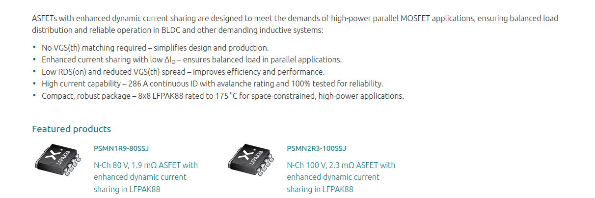
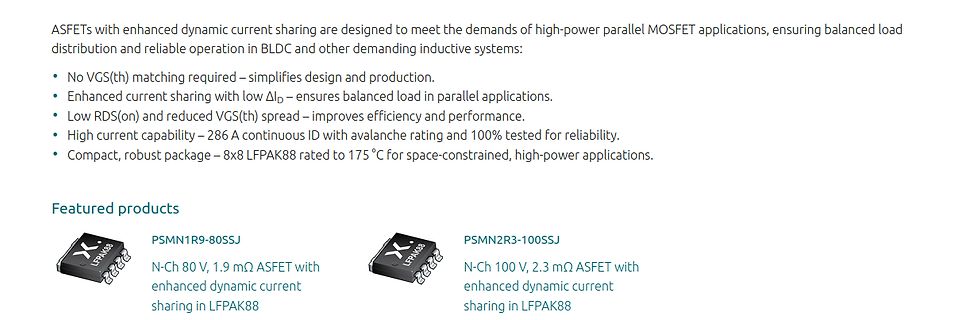
Produktbeschreibung von ASFETs für parallele MOSFET-Anwendungen
ASFETs with enhanced dynamic current sharing are designed to meet the demands of high-power parallel MOSFET applications, ensuring balanced load distribution and reliable operation in BLDC and other demanding inductive systems: • No VGS(th) matching required – simplifies design and production. • Enhanced current sharing with low ΔID – ensures balanced load in parallel applications. • Low RDS(on) and reduced VGS(th) spread – improves efficiency and performance. • High current capability – 286 A continuous ID with avalanche rating
-
Artikel
Transistor-Übersicht
Stromspiegel Rei, Far alldatasheet.com 0,19 ULN2801 ULN2802 ULN2803 ULN2804 DIL18 SO18 50 0,35 1 kHz 8x Low-Side NPN-Darlington, Freilaufdiode, max 500mA insgesamt Rei, Far, alle alldatasheet.com 0,35 - 0,50 UDN2981 DIL18 SO18 50 0,35 1 kHz 8x High-Side NPN-Darlington, Freilaufdiode, max 500mA insgesamt,
Farnell: Parametrische Suche beim Hersteller. Infineon Diodes (vormals Zetex) NXP Small-Signal NXP low VCEsat ONsemi
-
 Bild
Bild
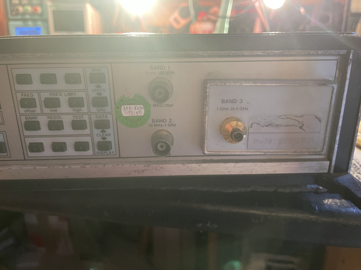
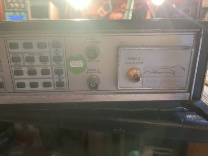
Frontansicht eines Spektrumanalysators
BAND 1 10 Hz-100 MHz FREQ FREQ LIMIT MHz UNITS offset low high GHz BAND RESOL TEST DATA CLEAR DISPLAY SKD-E070 12/95 BAND 2 10 MHz-1 GHz BAND 3 1 GHz-26.5 GHz
-
Thread
Anhängererkennung über Lampe
B=0, halte Out Ich habe erkannt, dass ich das Signal in 3 Pegel aufteilen muss. Also einmal High von der Referenzspannung & Low damit ich weiss ob der Hänger dran ist und ein separates 24V High Pegel von der Bremse. Wenn dieses High ist, soll die Schaltung nichts am Ausgang ändern. Ich muss
-
Thread
Visual Studio Code für Raspberry Pi Pico, neue Mikrocontroller uvam
[c] Smiths Interconnect, a subsidiary of U.K.-based Smiths Group plc, is a leading provider of high-reliability connectivity products and solutions serving the aerospace and defense, medical, semiconductor test and industrial markets. [/c] ### Raspberry Pi Pico: Visual Studio Code-Erweiterung
681815/6.png) Bildquelle, beide: https://www.rohm.com/products/diodes/schottky-barrier-diodes/ultra-low-vf/rbe01vym6afh-product ### CircuitPython-Update für ESP32-C61 Im Hause Adafruit gibt es ein weiteres Update für die hauseigene Python-Umgebung, das sich an den Neuerungen in Sachen Espressif orientiert
-
Thread
Umkopieren von Festplatten extrem langsam
hier: https://en.wikipedia.org/wiki/USB_communications#Signaling_rate_(transmission_rate)) Und Low-Speed ist im wesentlichen für HID (Tastaturen & Mäuse) vorgesehen. Low-Speed unterstützt /keine/ "bulk transfers", und die sind u.a. für MSD erforderlich. Roland E. schrieb im Beitrag #7960539:
LowSpeed-Gerät wieder beim Host auf.
-
Thread
Merten KNX-Netzteil 683829 - defekt
nicht ganz sicher ... wegen dem Aufdruck "5l" ?!? EE-A 47U 400B -- Elko radial, 47µF, 400V, 105°C,high ripple VF 100/16 P-D -- Elko SMD, 100µF, 16V, 2000h, low ESR
-
 Bild
Bild
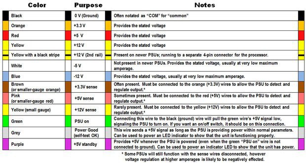
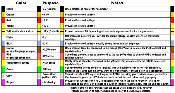
Tabelle der PC-Netzteil-Kabelbelegung
the processor. White -5 V Not present in newer PSUs. Provides the stated voltage, usually at very low maximum amperage. Blue -12 V Provides the stated voltage, usually at very low maximum amperage. Brown (+3.3V sense) Often present. Must be connected to the orange (+3.3V) wires to allow the PSU to detect
-
Thread
Türklingelschaltsignal an ESP anschließen
von dem GPIO nach GND erhöht die Sicherheit gegen eine Fehlauslösung durch ESD. GPIO abfragen, High=Taster offen, Low=Taster gedrückt. Fertig.
GPIO nach > GND erhöht die Sicherheit gegen eine Fehlauslösung durch ESD. > > GPIO abfragen, High=Taster offen, Low=Taster gedrückt. > > Fertig. Kann ich voll unterstützen: Andrea B. schrieb im Beitrag #7956849: > Verbinde den IN-Eingang des Gong mit GND des ESP32 und die +3V des Gong
-
Thread
LEDs mit PWM dimmen - Komponentenauswahl, was bedenken?
pro Kanal 25mA liefern, da sollten die 220Ohm bei 3,3V > eigentlich passen Nein, er kann bei high nur 10mA liefern bei 3.3V Versorgung und das auch nur wenn sein open Drain Ausgang auf Push-Pull umprogrammiert wurde. Lars G. schrieb im Beitrag #7956726: > ich frage mich nur, ob beispielsweise
spart auch den 220Ohm Widerstand. Da du nur 3.3V hast, muss es ein bei 2.7V voll durchschaltender LowLogicLevel sein, da du nur 0.5A schalten willst tut es ein IRLML2502 locker. Aber die Ausgänge sind nicht kurzschlusssicher. Es nützt auch nichts, wenn dein Netzteil nur 4A liefern könnte. Und eine