-
Thread
Unser Internet ist schon wieder abgesoffen
der Telekom und vom Vergleichsportal noch dicke Prämien obenauf. Wechseln wird immer belohnt. Als side effect sammeln sich immer mehr Telefonnummern an, da man jedesmal wieder drei neue dazu bekommt. Weiß nicht, wozu das gut sein soll. Hab inzwischen wohl zwölf Rufnummern, von denen ich nur drei kenne
-
Thread
Suche einfache Möglichkeit 24V 6A DC zu schalten
Das Heizelement wird bestimmt Low-Side geschaltet, mittels eines n-MOSFET. Da schaut man einfach mal was für einer verbaut ist, evtl kann der auch 24 V schalten.
>Das Heizelement wird bestimmt Low-Side geschaltet, mittels eines >n-MOSFET. Da schaut man einfach mal was für einer verbaut ist, evtl kann >der auch 24 V schalten. das scheint eine gute Idee zu sein, sich das mal auf dem Motherboard
-
 Bild
Bild
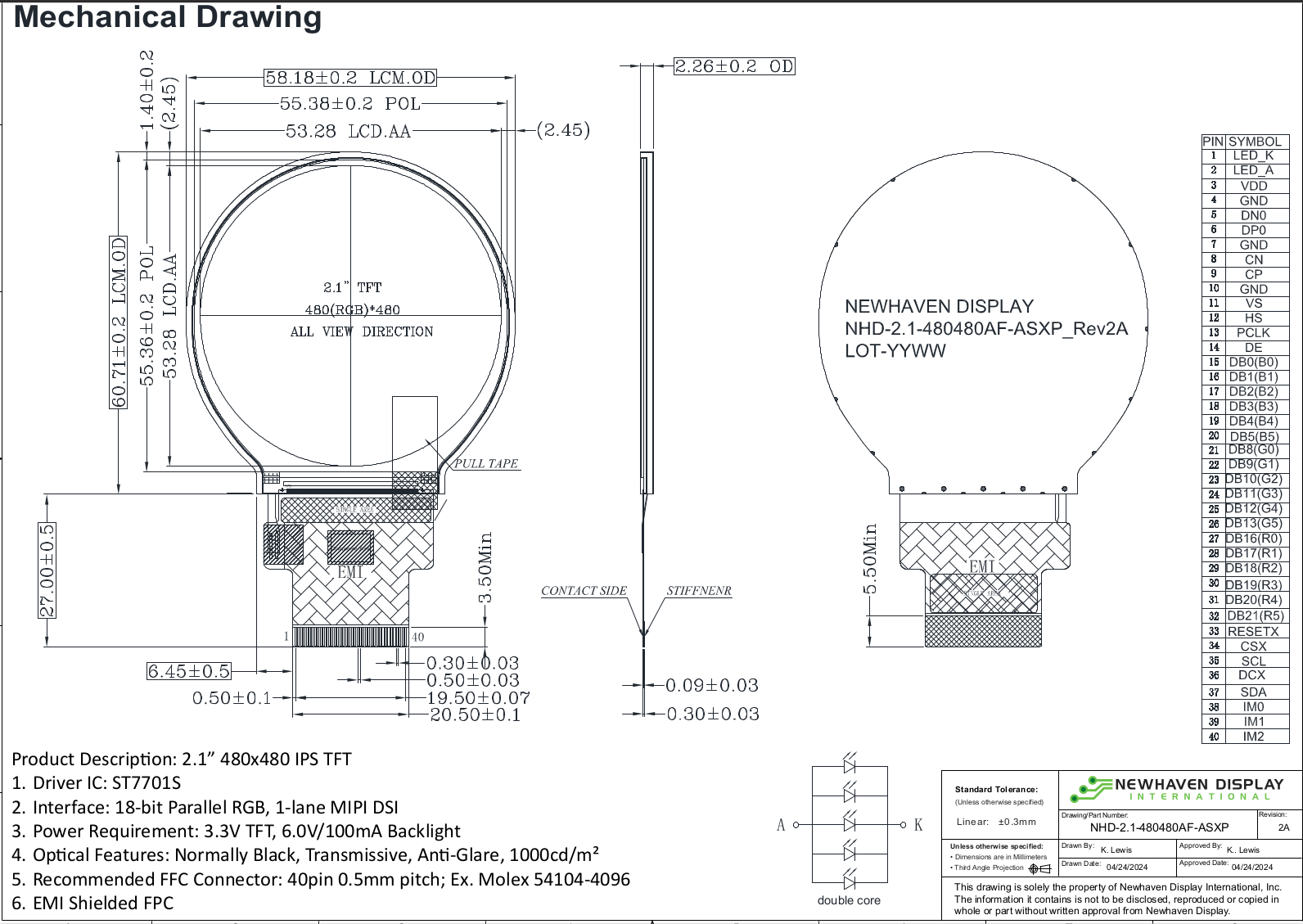
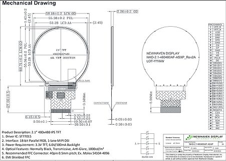
Technische Zeichnung eines 2.1 Zoll TFT-Displays
VIEW DIRECTION 2.26±0.2 OD NEWHAVEN DISPLAY NHD-2.1-480480AF-ASXP_Rev2A LOT-YYWW STIFFNENR CONTACT SIDE 5.50Min 27.00±0.5 EMI 3.50Min 6.45±0.5 0.50±0.3 19.50±0.07 20.50±0.1 0.30±0.03 0.50±0.03 0.30±0.03 0.09±0.03 PIN SYMBOL 1 LED K 2 VDD 3 LED A 4 GND 5 DDB0 6 GND 7 DP0 8 GND 9 CN 10 VSS 11 CP 12 GND
-
 Bild
Bild
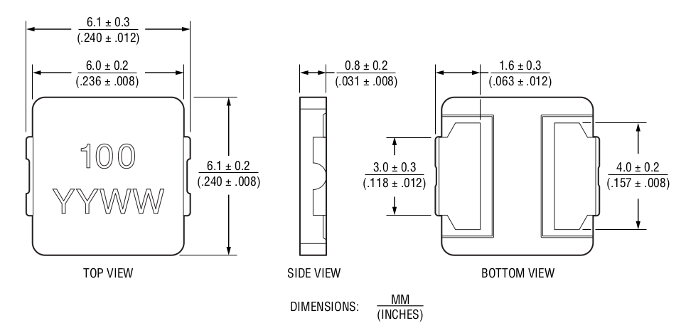
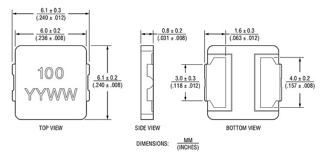
Technische Zeichnung eines Bauteils mit Abmessungen
0.2 (.031 ± .008) 1.6 ± 0.3 (.063 ± .012) 3.0 ± 0.3 (.118 ± .012) 4.0 ± 0.2 (.157 ± .008) TOP VIEW SIDE VIEW BOTTOM VIEW DIMENSIONS: MM (INCHES)
-
Thread
24V Digitaleingang EMV Störsicher machen
der Automation ganz normal. Und das sind keine Digital"PORTS" sondern Digitalausgänge. Mit High-Side Treiber davor.
-
Thread
Controller für Batteriebetrieb : Bootloader ?
eine viel zu hohe Spannung ab. Dafür solltest Du einen FET verwenden, Du suchst einen als "high-side-switch" bei Deinen nur 3V verwendbaren.
zu hohe Spannung ab. > > Dafür solltest Du einen FET verwenden, Du suchst einen als > "high-side-switch" bei Deinen nur 3V verwendbaren. IRLB8721 ?
-
Thread
Fenster offen - Erkennung (Im Winter)
von der Stange, installiert und eingerichtet in 5min. https://www.kaufland.de/product/502348345/?sid=68926261 Funktioniert auch im Sommer ;-) Einschränkung: wenn du bisher kein Zigbee-Gateway betreibst kommt das noch on top.
-
Artikel
Treiber
wobei auch gut 1A für 1µs schon eine Herausforderung darstellen kann. Definition zu Low- und High-Side Schalter. Low-Side–Schalter: Der FET schaltet eine Last gegen GND – auch als LS-Schalter bezeichnet. High-Side–Schalter: Der FET schaltet eine Last an die Versorgungsspannung – auch als HS-Schalter
Floating MOS-Gate Driver ICs , engl. Deep dive into the discrete design of a static charge-pump high-side gate-driver, Youtube-Video (englisch)
-
 Bild
Bild
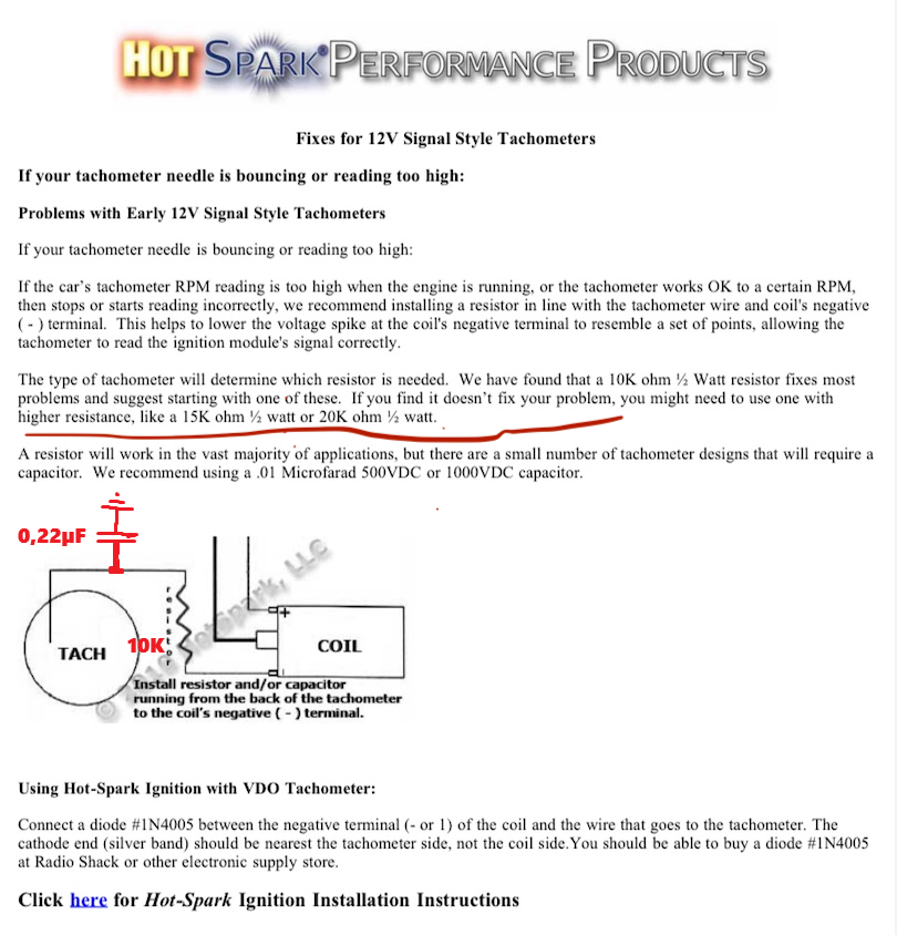
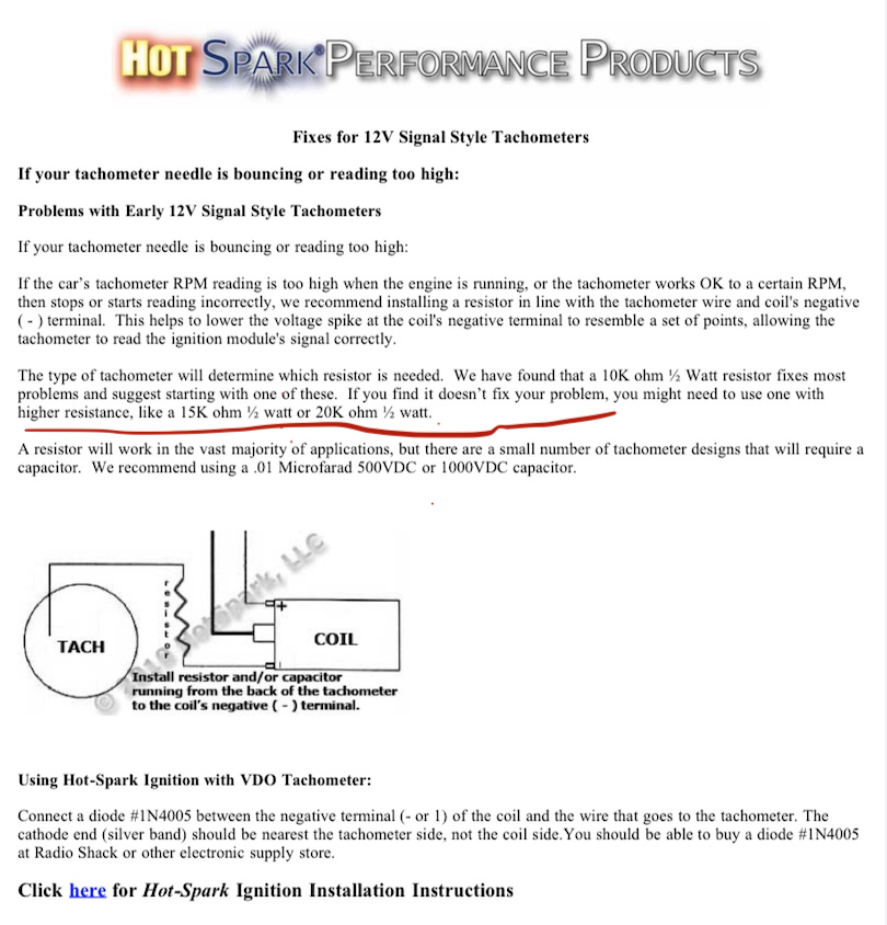
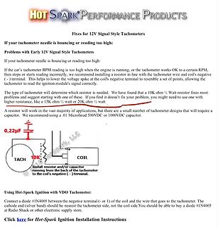
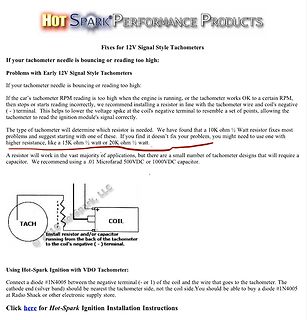
Anleitung zur Fehlerbehebung bei 12V Signal Style Tachometern
wire that goes to the tachometer. The cathode end (silver band) should be nearest the tachometer side, not the coil side. You should be able to buy a diode #1N4005 at Radio Shack or other electronic supply store. Click here for Hot-Spark Ignition Installation Instructions
-
 Bild
Bild
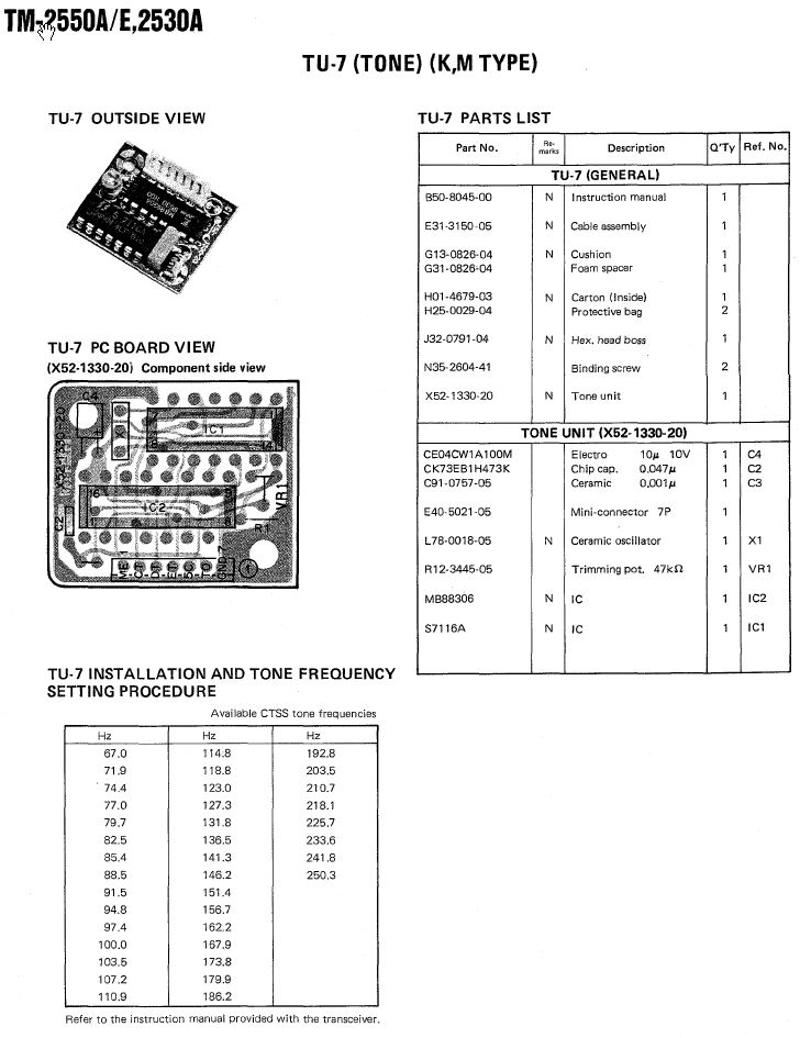
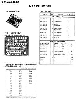
Technische Dokumentation TU-7 Tone Modul
N35-2604-41 Binding screw 2 X52-1330-20 N Tone unit 1 TU-7 PC BOARD VIEW (X52-1330-20) Component side view CE04CW1A100M Electro 10u 10V C4 CK73EB1H473K Chip cap 0,047u C2 C91-0767-05 Ceramic 0,001u C3 E40-5021-05 Mini-connector 7P N L78-0018-05 N Ceramic oscillator 1 X1 R12-3445-05 Trimming pot. 47k
-
 Bild
Bild
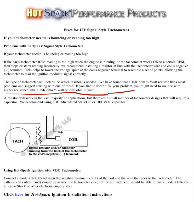
Anleitung zur Fehlerbehebung bei 12V Signal Style Tachometern
wire that goes to the tachometer. The cathode end (silver band) should be nearest the tachometer side, not the coil side. You should be able to buy a diode #1N4005 at Radio Shack or other electronic supply store. Click here for Hot-Spark Ignition Installation Instructions
-
Thread
Welche war bisher die weiteste Funkverbindung?
unten. Kommt darauf an wie seine Bahn-ebene zum Mondorbit stand. Und wenn er grad auf der "dark side" flog, wars wohl nichts mit QSO wegen Funkschatten. https://www.spiegel.de/wissenschaft/weltall/nasa-apollo-10-astronauten-hoerten-bizarre-toene-hinterm-mond-a-1078801.html Und wer weiss, ob nicht
-
 Bild
Bild
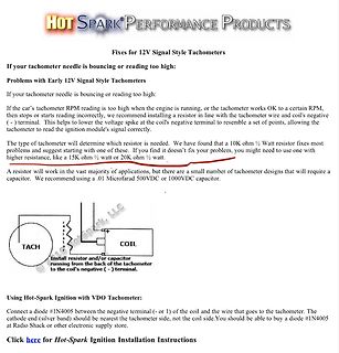
Anleitung zur Fehlerbehebung bei 12V Signal Style Tachometern
wire that goes to the tachometer. The cathode end (silver band) should be nearest the tachometer side, not the coil side. You should be able to buy a diode #1N4005 at Radio Shack or other electronic supply store. Click here for Hot-Spark Ignition Installation Instructions
-
Thread
Kleine 12V Platine für 3x Side LEDs
Ich würde gerne die gleiche Art von Platine fertigen lassen, jedoch aus Platzgründen nur mit 3x Side LEDs. Wie ist dies am einfachsten zu lösen? Es sollte kurzschlussfest sein. Und eben für KFZ Spannung möglich (14-11V) Sollte eine kleine Steuerung sein zum Bau eigener beleuchteter Einstiegsleisten
Ich würde gerne die gleiche Art von Platine fertigen lassen, jedoch aus > Platzgründen nur mit 3x Side LEDs. Wie hast du vor eine solche neue Platine zu machen? Selbst wenn du den Schaltplan hättest? Kannst du Schaltplan, Layout und Fertigungsdaten in einem entsprechenden Programm erstellen?
-
 Bild
Bild
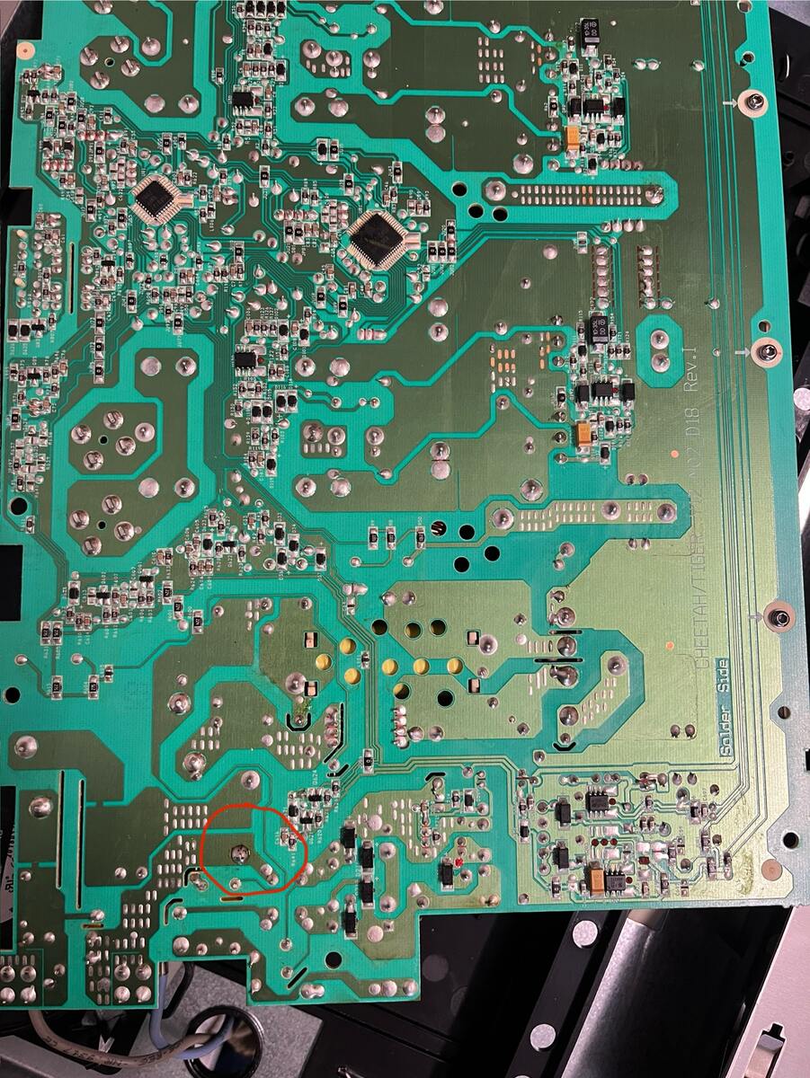
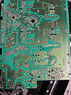
Nahaufnahme einer grünen Leiterplatte
Rev.J 2018 Solder Side
-
Thread
BT 2.1 dongle (WIN10) zu Bluetooth audio Receiver Board, not connect
Hmmm schrieb im Beitrag #7780123: > A2DP-Profil ok, backward compatibility from the receiver side is the issue. Also technisch könnte ein bt 2.1 dongle schon audio streamen. ? Also WIN10 erkennt das BT modul einfach nicht.
-
Thread
LED-Uhr mit Attiny26
Anleihen nehmen, um diskrete Transistoren durch Transistorarray zu ersetzen. Hier der UDN2981 als High-Side-Schalter für die Digits und einen ULN2804 als Low-Side-Schalter für die Segmente. Alexander H. schrieb im Beitrag #7786718: > Was braucht man denn alles, um aus dem Bascomcode eine .hex-Datei zu
0-Pegel hat, der Basisstrom des PNP in den Controllereingang fließt, Controller schaltet somit Lo-Side. Ergo: es wird eine 0 benötigt um deinen PNP zu schalten, damit der +5V an ein einzelnes Segment anlegen kann. Was macht nun der UDN6118? Wieder vorneweg: er benötigt einen High-Pegel um eine
-
 Bild
Bild
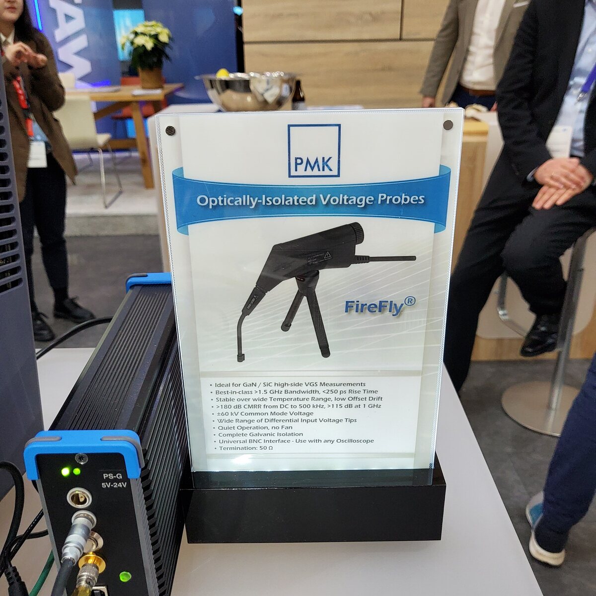
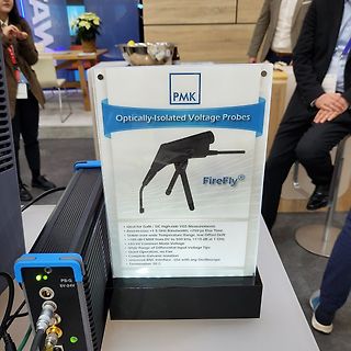
Werbeschild für optisch isolierte Spannungstastköpfe
PMK Optically-Isolated Voltage Probes FireFly® • Ideal for GaN / SiC high-side VGS Measurements • Best-in-class >1.5 GHz Bandwidth, <250 ps Rise Time • Stable wide Temperature Range, low Offset Drift • >180 dB CMRR from DC to 500 kHz, >115 dB at 1 GHz • <60 V Common Mode Voltage
-
 Bild
Bild
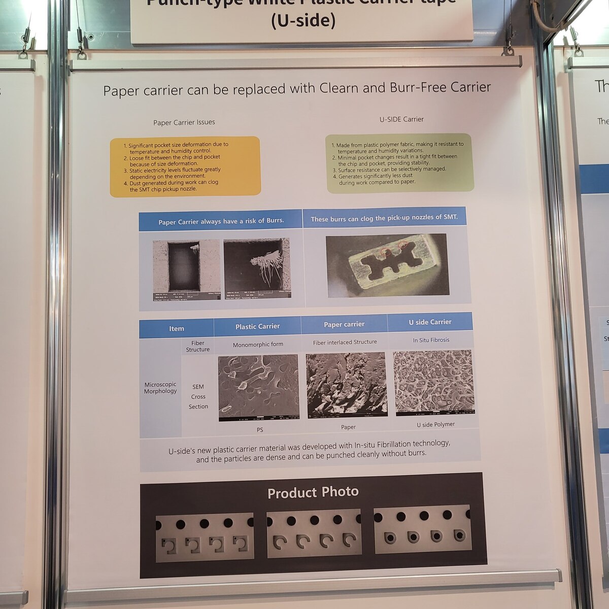
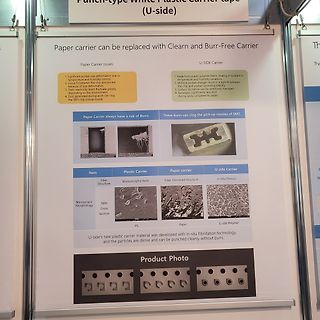
Infoplakat zu Kunststoff-Carrier-Tape für SMT-Bauteile
Punch-type White Plastic carrier tape (U-side) Paper carrier can be replaced with Clearn and Burr-Free Carrier Paper Carrier Issues 1. Significant pocket size deformation due to temperature and humidity control 2. Loose fit between the chip and
-
 Bild
Bild
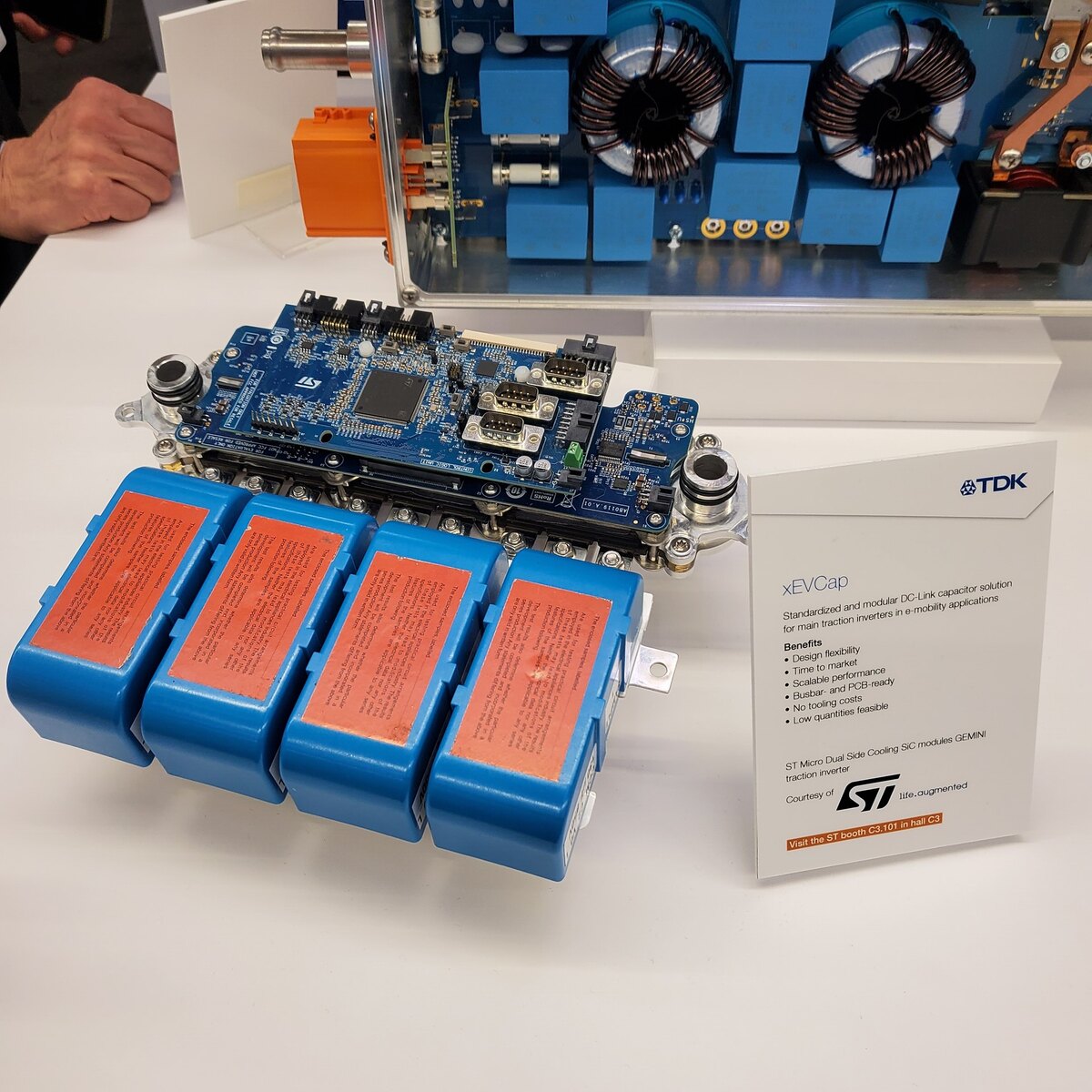
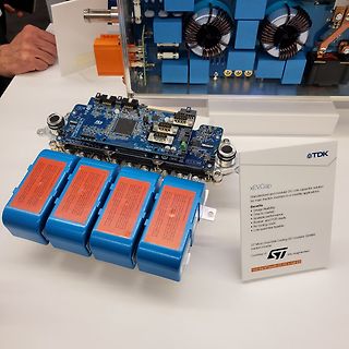
TDK xECap DC-Link Kondensator-Modul und Leistungselektronik
Integrated performance • Busbar and PCB ready • No tooling costs • Low quantities feasible ST Micro Dual Side Cooling SiC modules GEMINI traction inverter Courtesy of STMicroelectronics Visit the ST booth C3.101 in hall C3
-
 Bild
Bild
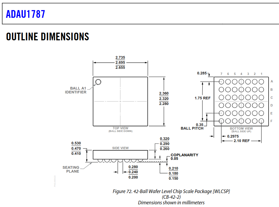
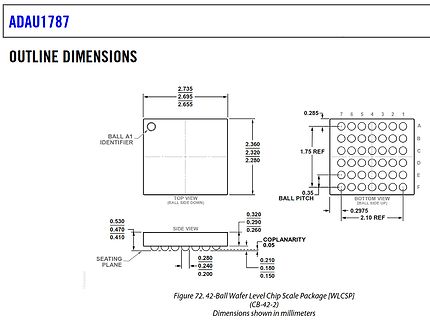
Geometrische Abmessungen eines WLCSP-Gehäuses
ADAU1787 OUTLINE DIMENSIONS BALL A1 IDENTIFIER TOP VIEW (BALL SIDE DOWN) 2.735 2.695 2.655 2.360 2.320 2.280 0.285 7 6 5 4 3 2 1 1.75 REF 0.35 BALL PITCH BOTTOM VIEW (BALL SIDE UP) 0.2975 2.10 REF SIDE VIEW 0.530 0.470 0.410 0.320 0.290 0.260 COPLANARITY 0.05 SEATING
-
 Bild
Bild
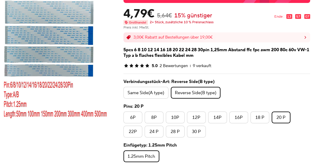
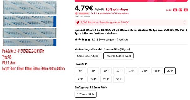
Screenshot eines Online-Shops für FFC-Flachbandkabel
VW-1 Typ a b flaches flexibles Kabel mm 5.0 2 Bewertungen 9 verkauft Verbindungsstück-Art: Reverse Side(B type) Same Side(A type) Reverse Side(B type) Pins: 20 P 6P 8P 10P 12P 14P 16P 18 P 20 P 22P 24 P 28 P 30 P Einfügetyp: 1.25mm Pitch 1.25mm Pitch
-
 Bild
Bild
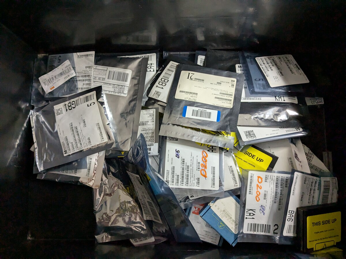
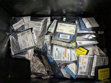
Verschiedene kleine Beutel mit Etiketten in einer Kiste
CB1, 21, THY, SAMPLES, SIDE UP, D200, KA1, BA6
-
Thread
Stromversorgung für ein LCD LED-Backlight
Danke Lenny! ich gucke mir das an. Die Side-LEDs bestehen aus zwei Gruppen. Die je ihre 75mA@50V bekommen. Also müsste man die vom CA-266 Board auch gut 2x abgreifen können, dachte ich..
-
Thread
Werkstatt Reduzierung Gesperrt
direkten Link, es brauch sich auch niemand anmelden. https://www.mega-hz.de/forum/viewforum.php?f=11&sid=8dedbba04f639d37b70a8525f7d3936c Einfacher gehts doch kaum, oder?
Link, es brauch sich auch niemand > anmelden. > https://www.mega-hz.de/forum/viewforum.php?f=11&sid=8dedbba04f639d37b70a8525f7d3936c Ich sehe dort weder ordentliche Artikelbeschreibungen noch Bilder. Jörg W. schrieb im Beitrag #7775317: > Wenn Rene jetzt nicht sein Interesse angemeldet hätte
-
 Bild
Bild
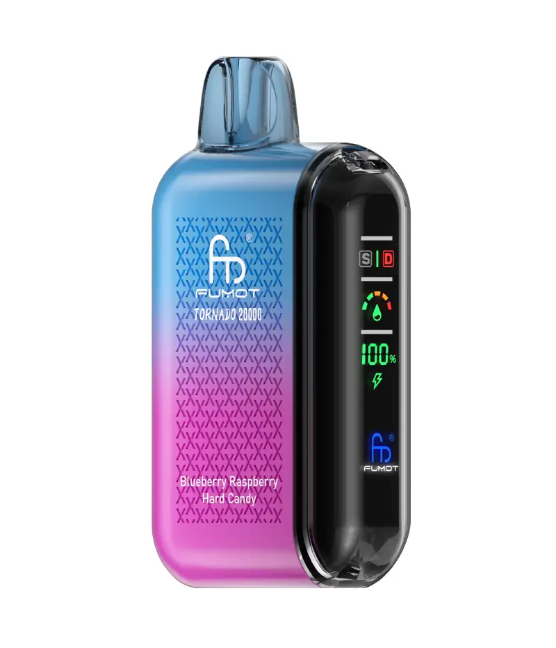
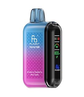
Fumot Tornado 20000 E-Zigarette
FUMOT TORNADO 20000 SID 100% FUMOT Blueberry Raspberry Hard Candy
-
Thread
KP902A in P-Kanal ?
besonders sportlich klingt. Aber selbst bei Motorbrücken betreibt man lieber Klimmzüge, die High-Side ebenfalls in N auszuführen. Hast du mal bei Infineon/ex. IR geschaut, was die so im Programm haben?
-
Thread
Drehkranz selbst fräsen
deinem Drehkranz zeigst du dort. +1 https://forum.zerspanungsbude.net/download/file.php?id=511224&t=1&sid=23d98435a121ae5836be3a7e70a48fe6
-
Thread
USB-C Kabel D+/D- nur einseitig belegt
specification allows shorting of the D+/D– lines together (D+ to D+ and D– to D–) on the receptacle side. Regardless of cable orientation, the PHY will always see the cable’s D+/D– pair"
-
 Bild
Bild
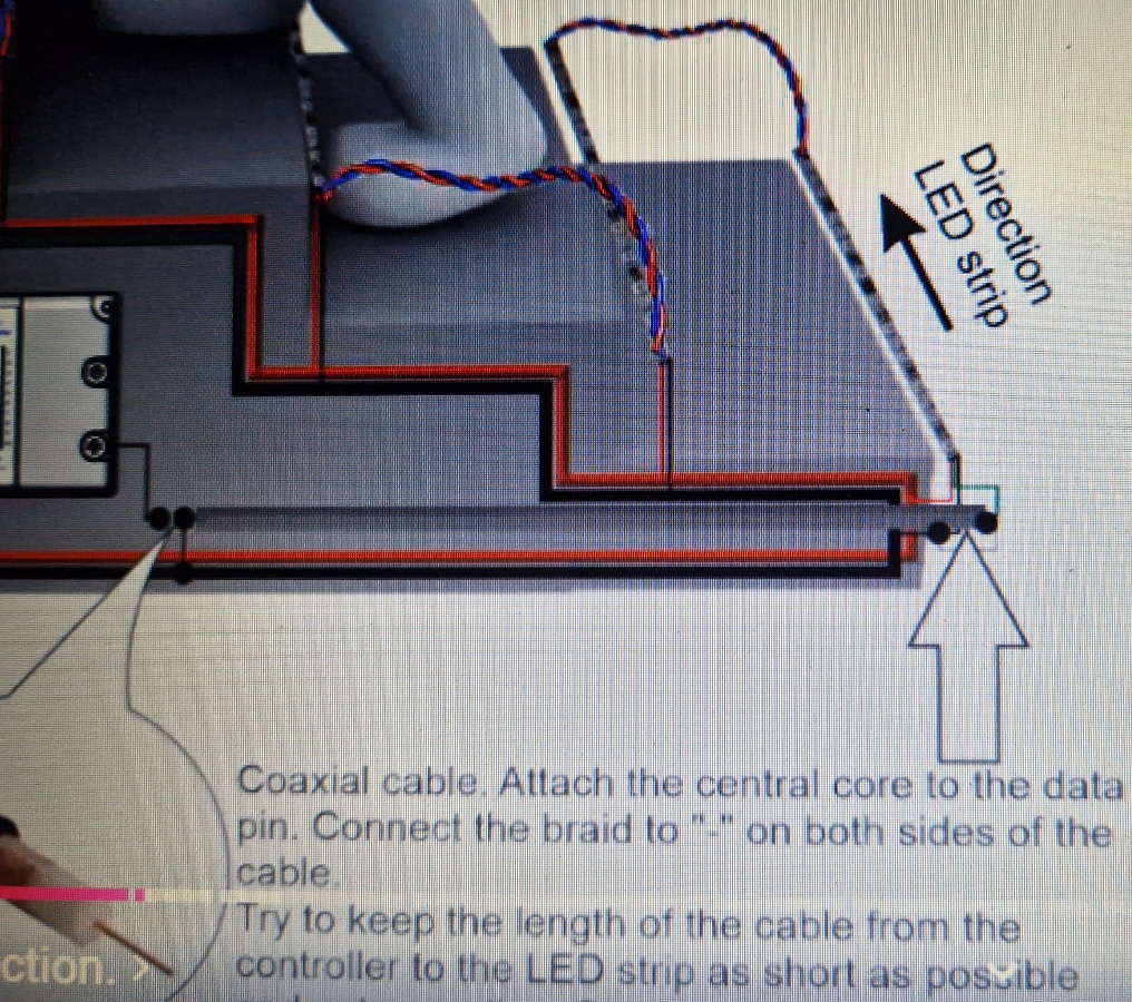
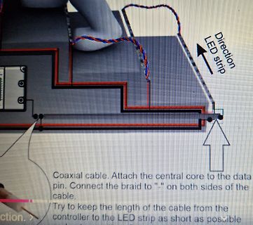
Verdrahtungsschema für LED-Streifen mit Koaxialkabel
LED strip Coaxial cable. Attach the central core to the data pin. Connect the braid to "-" on both sides of the cable. Try to keep the length of the cable from the controller to the LED strip as short as possible
-
 Bild
Bild
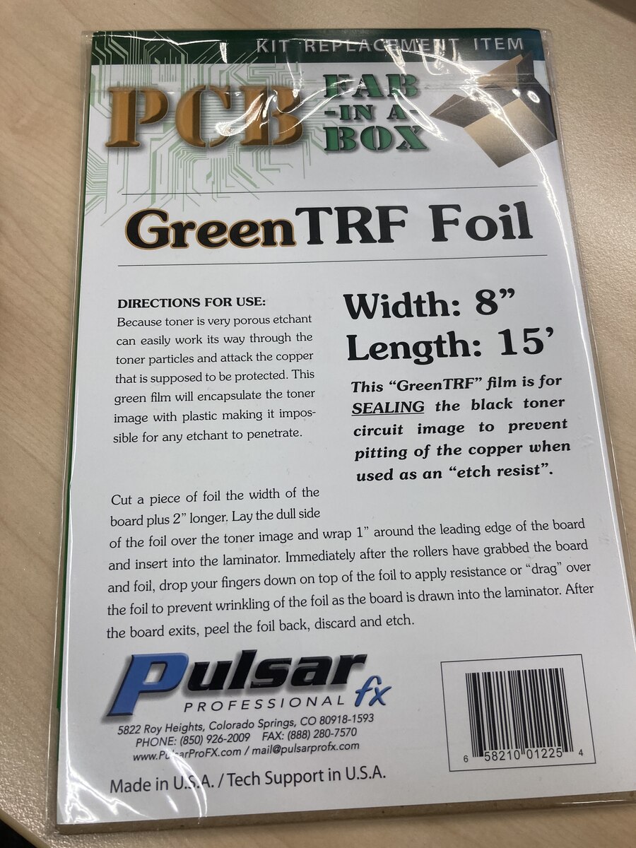
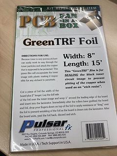
Verpackung von GreenTRF Foil für PCB-Ätzprozesse
used as an "etch resist". Cut a piece of foil the width of the board plus 2" longer. Lay the dull side of the foil over the toner image and wrap 1" around the leading edge of the board into the laminator. Immediately after the rollers have grabbed the board and foil, drop your fingers down on top of
-
Thread
Sicherungswiderstand identifizieren Hilfe
filterapplied=filter_Nennstrom%257E%257EA%3D1%26filter_Ausl%25C3%25B6se-Charakteristik%3DTr%25C3%25A4ge&sid=551d91899d493fa93f65a27a529a3af8e7a18a6b&itemList=category
-
 Bild
Bild
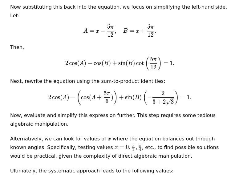
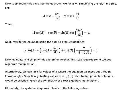
Mathematische Herleitung einer trigonometrischen Gleichung
Now substituting this back into the equation, we focus on simplifying the left-hand side. Let: A = x - 5π/12, B = x + 5π/12. Then, 2 cos(A) - cos(B) + sin(B) cot(5π/12) = 1. Next, rewrite the equation using the sum-to-product identities: 2 cos(A) - (cos(A + 5π/6)) + sin(B) (-2 / (3 + 2√
-
Thread
Neues aus der KI
) and a grandiose, timely scheme, balancing spectacle with deeper commentary on innovation’s dark side.
of a James Bond villain. They're usually wealthy, have grand schemes, charismatic but with a dark side, maybe some technological edge, and a personal vendetta or a desire for world domination. Elon Musk is a real person, so I should be careful not to make assumptions about his character. But in terms