
-
Datei
bsp.txt
Bsp.: CASE p1 IS WHEN "00000" => y <= '0'; WHEN "10000" => IF x >= z THEN y <= '1'; ELSE y <= '0'; END IF; WHEN OTHERS => y <= '0'; END CASE;
-
Datei
JobList.vhd
; Job: process(CommandAdress) begin DoneCommandIntern <= '0'; Error <= '0'; case CommandAdress is when x"0001" => Value1 <= CommandValue; DoneCommandIntern <= '1'; when x"0002" => Value2 <= CommandValue; DoneCommandIntern <= '1'; when x"0003" => Value3 <= CommandValue; DoneCommandIntern <= '1'; when others => Error <= '1'; end case; end process Job; MemAdressP: process(DoneCommandIntern) begin if (DoneCommandIntern = '1') then sMemAdress = MemAdress <= std_logic_vector(to_unsigned(sMemAdress+1, MemAdress'length
-
PDF
AT89S8253_Errata.pdf
treated as a Errata Sheet direct move to SCON such as MOV SCON,#IMM. These instructions may be used when it is not possible for the interrupt to occur at the same time as the instruction is being executed, which means in the following circumstances: A. The UART is not currently operating, or B. Within
in „Frage zu Errata Sheet“ · Mikrocontroller und Digitale Elektronik ·
-
PDF
Display.pdf
conditions. - The LCD module is coated with a film to protect the display surface. Exercise care when peeling off this protective film since static electricity may be generated. u Storage Precautions When storing the LCD modules, avoid exposure to direct sunlight or to the light of fluorescent lamps
in „Grafik LCD mit AVR“ · Mikrocontroller und Digitale Elektronik ·
-
PDF
LCD_64128A_LED.pdf
RAM to output register) Reset System reset can be initialized by setting RSTB terminal at low level when turning power on, receiving instruction from MPU. When RSTB becomes low, following procedure is occurred. - Display off - Display start line register becone set by 0.(Z-address 0) While RSTB is low
in „Displaytech 64128 mit LPC2119 ansteuern“ · Mikrocontroller und Digitale Elektronik ·
-
PDF
LCD64128A_DIS.pdf
RAM to output register) Reset System reset can be initialized by setting RSTB terminal at low level when turning power on, receiving instruction from MPU. When RSTB becomes low, following procedure is occurred. - Display off - Display start line register becone set by 0.(Z-address 0) While RSTB is low
in „64x128 Pixel Display funktioniert nicht“ · Mikrocontroller und Digitale Elektronik ·
-
PDF
VHDL_Coding_eng.pdf
considerably reduce the design risks. If you do not agree with some rules, or want to suggest adding others, please fell free to contact me : Bert Cuzeau. Technical Manager ALSE - info@alse-fr.com. Conventions RTL : Register Transfer Level (almost equivalent to « synthesizable »). BEH : Behavioral code almost
-
PDF
Display.pdf
dry conditions. -The LCD module is coated with a film to protect the display surface. Exercise care when peeling off this protective film since static electricity may be generated. Storage precautions When storing the LCD modules, avoid exposure to direct sunlight or to the light of fluorescent lamps.
in „8 bit LCD an MSP430F2132“ · Mikrocontroller und Digitale Elektronik ·
-
PDF
AM-480272MTMQW-00H-_HSD043I9W1_.pdf
than HB pencil lead. (2) Use fingerstalls of soft gloves in order to keep clean display quality, when persons handle the LCD module for incoming inspection or assembly. (3) When the surface is dusty, please wipe gently with absorbent cotton or other soft material. (4) Wipe off saliva or water drops
in „TFT-LCD HSD043I9W1“ · Mikrocontroller und Digitale Elektronik ·
-
PDF
AND9100-D.pdf
is the primary static parameter Those internal to the IGBT are dealt with by selecting an to use when calculating static variations as it directly relates appropriate device and those external to the IGBT are to the conduction loss of the transistor. The handled by good system design. This paper will
in „Ersatz-Transistor für Schweißgerät“ · Analoge Elektronik und Schaltungstechnik ·
-
 Bild
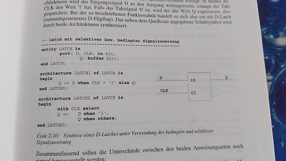
Buchseite mit VHDL-Code und Schaltsymbol eines D-Latches
is port( D, CLK: in bit; Q: buffer bit); end LATCH; architecture LATCH1 of LATCH is begin Q <= D when CLK = '1' else Q; end LATCH1; architecture LATCH2 of LATCH is begin with CLK select Q <= D when '1', Q when others; end LATCH2; Code 2-10: Synthese eines D-Latches unter Verwendung der bedingten und
in „Anfängerfrage- LatticeDiamond (XO2) - VHDL - 2 x architecture im Modul“ · FPGA, VHDL & Co. · · Fotos
-
PDF
doc8377.pdf
four LEDs are active low. LED0, LED2, and LED3 are shared with the three mechanical buttons (SW0:2). When turning an LED on, set the I/O pin to output low. When turning an LED off, set the I/O pin as input with pull-up. The protection circuitry added to the button will make the LED shine brighter when the
in „[V] MEGA-1284P-XPLAINED“ · Markt ·
-
PDF
Atmel-2508-Zero-Cross-Detector_ApplicationNote_AVR182.pdf
at the actual switching point. To get this noise as low as possible the ideal switching would be when the amplitude is 0 volt. The amplitude is crossing 0 volt at the sinus “zero crossing”. Switching mains in and out at the zero crossing requires a way of detecting when the next crossing will be and
in „230 Volt Spannungsmessung via Widerstand“ · Analoge Elektronik und Schaltungstechnik ·
-
PDF
Atmel-2508-Zero-Cross-Detector_ApplicationNote_AVR182.pdf
at the actual switching point. To get this noise as low as possible the ideal switching would be when the amplitude is 0 volt. The amplitude is crossing 0 volt at the sinus “zero crossing”. Switching mains in and out at the zero crossing requires a way of detecting when the next crossing will be and
in „Überspannung bei Attiny Input Pins“ · Mikrocontroller und Digitale Elektronik ·
-
PDF
Atmel-2508-Zero-Cross-Detector_ApplicationNote_AVR182.pdf
at the actual switching point. To get this noise as low as possible the ideal switching would be when the amplitude is 0 volt. The amplitude is crossing 0 volt at the sinus “zero crossing”. Switching mains in and out at the zero crossing requires a way of detecting when the next crossing will be and
in „Arduino: max. Strom duch interne Schutzdioden“ · Mikrocontroller und Digitale Elektronik ·
-
PDF
FLASHMCUProgrammerforFR.pdf
4) for making and setting a cipher file. a. Erase This is a special command that is not verified. When it is executed, all data programmed to flash memory is erased. b. Full Operation This command is not verified. The old program is replaced by the new one even verification is unsuccessful. When the
in „Fujitsu MB91F011 internal flash read/write“ · Mikrocontroller und Digitale Elektronik ·
-
Datei
SerialAdder.vhd
"; Loadsignal <= '1'; NextSTATE <= NEWITERATION; when NEWITERATION=> AngleOutput<= "ZZZZZZZZZZZZZZZZ"; if Iteration = 11 then NextSTATE <= IDLE; else NextSTATE <= SUM; end if; when Sum=> AngleOutput<= "ZZZZZZZZZZZZZZZZ"; if AddCounter = 15 then NextSTATE
in „inkompatible Komponenten in meinem Desgin“ · FPGA, VHDL & Co. ·
-
PDF
ltn154x3-l06.pdf
designed so as not to produce too much leakage current from high-voltage output of the inverter. When you design or order the inverter, please make sure that a poor lighting caused by the mismatch of the backlight and the inverter(miss lighting, flicker, etc.) never occur. When you confirm it, the module
in „BeagleBoard LVDS Transmitter“ · Mikrocontroller und Digitale Elektronik ·
-
Datei
AxConv.vhd
stateConv := 0; ceAinkr <= '0'; cemul <= '0'; cediv <= '0'; ceTO16 <= '0'; ELSE CASE stateConv IS WHEN 0 => IF ceConv = '1' THEN-- AFPint = Achsenwinkel in RAD FP ceAinkr <= '1'; --start AinkrFP := AFPint * C_AxRad[Inkr/Rad] stateConv := 1; ELSE stateConv := 0; END IF; WHEN 1 => --AinkrFP := AFPint *
-
Datei
top_HALLO.vhd
<= fsm_init ; when 1 => st_FSM <= fsm_H ; when 2 => st_FSM <= fsm_A ; -- wechseln in nächsten Zustand, abhängig von si_Hallo when 3 => st_FSM <= fsm_L ; when 4 => st_FSM <= fsm_L2 ; when 5 => st_FSM <= fsm_O ; when 6 => st_FSM <= fsm_end ; when others => st_FSM <= fsm_init ; end case; else st_FSM <= fsm_wait; end if; when fsm_H => s1_Steuer <= '1' ; --s12_AD <="011111111111"; s1_SPI_Enable <= '1'; st_FSM <= fsm_wait ; vi_Cnt_Wait := 200000
in „Textausgabe mittels SPI an Lattice FPGA“ · FPGA, VHDL & Co. ·
-
PDF
4P018-00_03_G2_Aurora_Mb_COG_Driver_Interface_Timing_for_small_size_20150727.pdf
Input 16 thData Byte 1 1 Scan on {D(7,y),D(5,y), S(1) ~S(96) D(3,y), D(1,y)} 0 0 Scan off Example: When y = 2, 1stScan Byte à Only S(2) is Scan on (11) while others are {S(96),S(95), S(94), S(93)} Scan off (00). The image represented by Data Bytes will be displayed on 2dhorizontal line Total displayed
in „Probleme mit Breakoutboard für 2" Pervasive Display“ · Mikrocontroller und Digitale Elektronik ·
-
PDF
4P018-00_03_G2_Aurora_Mb_COG_Driver_Interface_Timing_for_small_size_20150727.pdf
Input 16 thData Byte 1 1 Scan on {D(7,y),D(5,y), S(1) ~S(96) D(3,y), D(1,y)} 0 0 Scan off Example: When y = 2, 1stScan Byte à Only S(2) is Scan on (11) while others are {S(96),S(95), S(94), S(93)} Scan off (00). The image represented by Data Bytes will be displayed on 2dhorizontal line Total displayed
in „e Papier einzelne Bildpunkte setzen“ · Mikrocontroller und Digitale Elektronik ·
-
PDF
4P018-00_03_G2_Aurora_Mb_COG_Driver_Interface_Timing_for_small_size_20150727.pdf
Input 16 thData Byte 1 1 Scan on {D(7,y),D(5,y), S(1) ~S(96) D(3,y), D(1,y)} 0 0 Scan off Example: When y = 2, 1stScan Byte à Only S(2) is Scan on (11) while others are {S(96),S(95), S(94), S(93)} Scan off (00). The image represented by Data Bytes will be displayed on 2dhorizontal line Total displayed
in „Wie muss man Pervasive Displays beschreiben?“ · Mikrocontroller und Digitale Elektronik ·
-
PDF
4P018-00_03_G2_Aurora_Mb_COG_Driver_Interface_Timing_for_small_size_20150727.pdf
Input 16 thData Byte 1 1 Scan on {D(7,y),D(5,y), S(1) ~S(96) D(3,y), D(1,y)} 0 0 Scan off Example: When y = 2, 1stScan Byte à Only S(2) is Scan on (11) while others are {S(96),S(95), S(94), S(93)} Scan off (00). The image represented by Data Bytes will be displayed on 2dhorizontal line Total displayed
in „Suche Lösungsvorschlag zur Initialisierung eines Pervasiven Displays“ · Mikrocontroller und Digitale Elektronik ·
-
Datei
fsm_1process.vhd
; yout <= '0'; end if; when S1 => yout <= '0'; if ain = '1' then state <= S2; count_int <= count_int + 1; else state <= state; count_int <= count_int; end if; when S2 => yout <= '0'; if ain = '1' then state <= S0; count_int <= count_int + 1; else state <= state; count_int <= count_int; end if; when others => state <= S0; count_int <= "0000"; yout <= '0'; end case; end if; end if; end process; count <= std_logic_vector(count_int); end Behavioral;
in „Probleme bei Vivado Tutorial mit State Machine“ · FPGA, VHDL & Co. ·
-
Datei
ALU.vhd
downto 0)); end ALU; architecture Behavioral of ALU is begin Y <= signed(resize(A,8)) + resize(B,8) when op="00" else signed(resize(A,8)) + resize(B,8) + resize(B,8) when op="01" else signed(resize(A,8) + resize(A,8)) - resize(B,8) when op="10" else (others=>'0'); end Behavioral;
in „Gray Code und Zweierkomplement Addition“ · FPGA, VHDL & Co. ·
-
Datei
mux_2.vhd
std_logic_vector(1 downto 0) := "00"; begin s_vector <= i_Error & i_Ready; with s_vector select o_Out <= '0' when "00", i_Signal1 when "01", i_Signal2 when others; end;
-
PDF
3.2PI-SSD1289.pdf
set, be sure the module and your body have the same electric potential. Be sure to ground the body when handling the LCD modules. - Tools required for assembling, such as soldering irons, must be properly grounded. make certain the AC power source for the soldering iron does not leak. When using an electric
in „3.2" TFT Display - 3.3V Backlight - 3.3V VCC Pegel?!“ · Mikrocontroller und Digitale Elektronik ·
-
Datei
od-info.txt
’, unlike others, works when an odd number of bytes are read—the last byte is simply copied (since there is nothing to swap it with). ‘sync’ Pad every input block to size of ‘ibs’ with trailing zero bytes. When used
in „USB3-to-SATA Adapter - Fake oder Treiber Problem?“ · PC Hard- und Software ·
-
Datei
fsm_2process.vhd
next_state <= state; count_next <= count_int; yout <= '0'; end if; when S1 => yout <= '0'; if ain = '1' then next_state <= S2; count_next <= count_int + 1; else next_state <= state; count_next <= count_int; end if; when S2 => yout <= '0'; if ain = '1' then next_state <= S0; count_next <= count_int + 1; else next_state <= state; count_next <= count_int; end if; when others => next_state <= S0; count_next <= "0000"; yout <= '0'; end case; end process; end Behavioral;
in „Probleme bei Vivado Tutorial mit State Machine“ · FPGA, VHDL & Co. ·
-
PDF
XL4015-DC-DC-Module-Datasheet.pdf
package duty ratio linearly from 0 to 100%. An over current protection function is built inside. When short protection function happens, the operation frequency will be reduced from Applications 180KHz to 48KHz. An internal compensation LCD Monitor and LCD TV block is built in to minimize external Portable
in „PCB Schaltplan“ · Mikrocontroller und Digitale Elektronik ·
-
Datei
nex_4_pwm.vhd
end nex_4_pwm; architecture Behavioral of nex_4_pwm is signal pwm_zaehler: unsigned(15 downto 0):=(others => '0'); begin led <= sw; RGB1_Red <= '1' when pwm_zaehler <= unsigned(sw); RGB1_Green <= '1' when pwm_zaehler <= unsigned(sw); RGB1_Blue <= '1' when pwm_zaehler <= unsigned(sw); process begin wait
-
PDF
doc7559.pdf
resources, we obtain the following scheduling of the program Normal Operations This schedule is valid when the algorithm is running in standard operating condition, i.e. when the motor is operating (rotating) or is stopped. Indeed, position, speed and reference calcula- tions are refreshed when events occurs from the position sensors (hall effect sensors) or don't have to be done (when the motor is stopped in a stable and normal state). Figure 16. Task Scheduling When Normal Operation Computation of position, derivate speed, Edge on position sensor current reference PCINT9 interrupt
in „Stromflussabbruch mit Arduino Nano steuern?“ · Mikrocontroller und Digitale Elektronik ·
-
Datei
PWM.vhd
; end PWM; architecture rtl of PWM is -- Signale hierher signal count: unsigned (5 downto 0) := (others=>'0'); signal countout: integer range 0 to 31; signal PWM_out : std_logic :='0'; begin -- hier ungetaktete Kombinatorik count <= count+1 when rising_edge(clock) ; countout <= to_integer(count) when count(5)='0' else 31-to_integer(count(4 downto 0)); PWM_out <= '0' when count(5)= '0' else '1'; --process begin --wait until rising_edge(clock); -- getaktete Beschreibung hier --end process; -- ungetaktete Kombinatorik darf auch hier stehen end;
-
Datei
top_level.vhd
signals to form vector for case construct. rotary_in <= rotary_b_in & rotary_a_in; case rotary_in is when "00" => rotary_q1 <= '0'; rotary_q2 <= rotary_q2; when "01" => rotary_q1 <= rotary_q1; rotary_q2 <= '0'; when "10" => rotary_q1 <= rotary_q1; rotary_q2 <= '1'; when "11" => rotary_q1 <= '1'; rotary_q2 <= rotary_q2; when others => rotary_q1 <= rotary_q1; rotary_q2 <= rotary_q2; end case; end if; end process rotary_filter; -- -- The rising edges of 'rotary_q1' indicate that a rotation has occurred and the -- state of
in „Rotary Button“ · FPGA, VHDL & Co. ·
-
PDF
e_ek01_passhi.pdf
Design LCD Modules STN LCD Modules for Automobile STN LCD Modules for PDA Passive Matrix LCD Modules Others Graphic Type LCD Modules Stadard Design LCD Modules Character Type LCD Modules Introduction & Standard P-LCD Modules Modes Introduction • Hosiden offers from the panels only to module assemblies with
in „LCD Displays ohne Bezeichnung“ · Mikrocontroller und Digitale Elektronik ·
-
Datei
PWM.vhd
BREITE : unsigned(4 downto 0):="01000"; -- das ist der Wert 8. signal count : unsigned (5 downto 0):=(others=>'0'); signal countout : integer range 0 to 31; signal PWM_out : std_logic :='0'; begin -- hier ungetaktete Kombinatorik count <= count+1 when rising_edge(clock); countout <= to_integer(count) when count(5)='0' else 31-to_integer(count(4 downto 0)); PWM_0 <= '0' when count(5)= '0' else '1'; --process begin --wait until rising_edge(clock); -- getaktete Beschreibung hier --end process; -- ungetaktete Kombinatorik darf auch hier stehen end;
-
Datei
PWM.vhd
BREITE: unsigned(4 downto 0):="01000"; -- das ist der Wert 8. signal count: unsigned (5 downto 0) := (others=>'0'); signal countout: integer range 0 to 31; signal PWM_out : std_logic :='0'; begin -- hier ungetaktete Kombinatorik count <= count+1 when rising_edge(clock) ; countout <= to_integer(count) when count(5)='0' else 31-to_integer(count(4 downto 0)); PWM_out <= '1' when count >= BREITE else '0'; --process begin --wait until rising_edge(clock); -- getaktete Beschreibung hier --end process; -- ungetaktete Kombinatorik darf auch hier stehen end;
-
PDF
BC546-D.PDF
2.93 --- C V 3.43 --- SECTION X−X 1 N STYLES ON PAGE 2 Electronic versions are uncontrolled except when accessed directly from the Document Repository. DOCUMENT NUMBER: 98ASB42022B Printed versions are uncontrolled except when stamped “CONTROLLED COPY” in red. DESCRIPTION: TO−92 (TO−226) PAGE 1 OF 2 onsemi
in „5V Solid-State-Relais über 3.3V Logik steuern“ · Mikrocontroller und Digitale Elektronik ·
-
PDF
VoltageReference_AVR353.pdf
Atmel AVR Smart Battery devices contain a very accurate low power bandgap voltage reference which when calibrated correctly has less than 90ppm/°C drift from –10°C to +70°C and absolute accuracy of typically +/-1mV. This is the reference used for the internal Voltage ADC and Coulomb Counting ADC. ATmega16HVA
in „VRef = USB am Atmega“ · Mikrocontroller und Digitale Elektronik ·
-
PDF
Atmel-JTAGICE3_UserGuide.pdf
in use. When using STK600 or a board making use of the AVR JTAG pinout, the standard JTAG connector can be used. When connecting to a board which makes use of the ARM JTAG pinout, the 10-pin "mini-squid" cable must
in „Arduino Nano über ISP programmieren“ · Mikrocontroller und Digitale Elektronik ·
-
PDF
XGZP6857D-Pressure-Sensor-V2.9.pdf
be held stable at SDA when SCL is high. Data can change value at SDA only when SCL is low. I2C PROTOCAL XGZP6857D_DataSheet_EN_V2.9 www.CFSensor.com 5 /6 Calibrated Pressure Sensor Series V2.9/20250812 GENERAL REGISTER DESC.
in „CFSensors XGZP6857D Drucksensor Informationen“ · Mikrocontroller und Digitale Elektronik ·
-
PDF
KSGER_T12_Soldering_Station_Menue.pdf
operation ‘Tip Setup’. (See chapter 1.) 06. Temp Stepping - Temp: 1 – 50 (increment / decrement per click when changing tip temperature) 07. Password Set (used to lock the unit so others can not change settings) - Switch: On / Off (use the password, or not) - Lock: 1 – 60 minutes (password becomes active after
in „Lötstation Quikko / Ksger T12 dtl Vorteil?“ · Mechanik, Gehäuse, Werkzeug ·
-
PDF
AN1040-D.PDF
For addressing the isolation problem. lowest overall thermal resistance, which is quite important when high power must be dissipated, it is best to isolate the Insulator Thermal Resistance When an insulator is used, thermal grease is of greater entire heatsink/semiconductor structure from ground, rather
in „Welches Transistorgehäuse ist am besten zu kühlen?“ · Mikrocontroller und Digitale Elektronik ·
-
PDF
AN1040-D.PDF
For addressing the isolation problem. lowest overall thermal resistance, which is quite important when high power must be dissipated, it is best to isolate the Insulator Thermal Resistance When an insulator is used, thermal grease is of greater entire heatsink/semiconductor structure from ground, rather
in „Wärmewiderstand Rthg - Rthgk“ · Analoge Elektronik und Schaltungstechnik ·
-
PDF
AN1040-D.PDF
For addressing the isolation problem. lowest overall thermal resistance, which is quite important when high power must be dissipated, it is best to isolate the Insulator Thermal Resistance When an insulator is used, thermal grease is of greater entire heatsink/semiconductor structure from ground, rather
in „Gibt es Alternativen zu Silikonpads?“ · Mikrocontroller und Digitale Elektronik ·
-
PDF
AN1040-D.pdf
For addressing the isolation problem. lowest overall thermal resistance, which is quite important when high power must be dissipated, it is best to isolate the Insulator Thermal Resistance When an insulator is used, thermal grease is of greater entire heatsink/semiconductor structure from ground, rather
in „Kurzschluss durch Kühlörper?“ · Analoge Elektronik und Schaltungstechnik ·
-
PDF
AN1040-D.PDF
For addressing the isolation problem. lowest overall thermal resistance, which is quite important when high power must be dissipated, it is best to isolate the Insulator Thermal Resistance When an insulator is used, thermal grease is of greater entire heatsink/semiconductor structure from ground, rather
in „Reicht das Eloxal als Isolierung?“ · Mechanik, Gehäuse, Werkzeug ·
-
PDF
AN1040-D.pdf
For addressing the isolation problem. lowest overall thermal resistance, which is quite important when high power must be dissipated, it is best to isolate the Insulator Thermal Resistance When an insulator is used, thermal grease is of greater entire heatsink/semiconductor structure from ground, rather
in „MOSFET Power Dissipation“ · Analoge Elektronik und Schaltungstechnik ·
