max. 3℃/second max. Preheat: Temperature Min (Tsmin 100℃ 150℃ Preheat: Temperature Min (Tsmax 150℃ 200℃ Preheat: Time ( tmin tomax) 60-120 seconds 60-180 seconds Time Maintained Above: Temperature (T L 183 ℃ 217 ℃ Time Maintained Above: Time (tL) 60-150 seconds 60-150 seconds Peak/Classification Temperature
html https://www.amazon.de/Kartenleser-WARRKY-Highspeed-kartenleseger%C3%A4t-Windows/dp/B083W6VH1S/ref=sr_1_2_sspa?__mk_de_DE=%C3%85M%C3%85%C5%BD%C3%95%C3%91&crid=14I9NEI87KTFG&keywords=Kartenleser+CF&qid=1707491258&s=computers&sprefix=kartenleser+cf%2Ccomputers%2C89&sr=1-2-spons&sp_csd=d2lkZ2V0TmFtZT1zcF9hdGY
Strom darüber und damals war der GPU Strom so maximal 150mA was mit den Ports 50mA den Maxstrom von 200mA ergibt. Die neueren Taktzahlen sind höher die GPU stärker der Strom wohl höher, siehe Datenblätter wenn verfügbar.
dem rp2040 hat jemand einen Logikanalysator gebaut - 24 Kanäle und 100 Msps, und mit dem rp2350 auch 200 und sogar 400 Msps. https://github.com/gusmanb/logicanalyzer
places on the screen, in different colors and transparency: dl(COLOR_RGB(255, 64, 64)); // red at (200, 120) dl(VERTEX2II(200, 120, 0, 0)); dl(COLOR_RGB(64, 180, 64)); // green at (216, 136) dl(VERTEX2II(216, 136, 0, 0)); dl(COLOR_RGB(255, 255, 64)); // transparent yellow at (232, 152) dl(COLOR_A(150
registers. The BT815 CTSE supports Focaltech and Goodix touch controllers, as well as touch host mode (refer to section 4.8.7). For a supported CTPM list please refer to AN_336 FT8xx - Selecting an LCD Display. The BT815 uses the I2C address value in the REG_TOUCH_CONFIG register to differentiate Focaltech
Input pulse duration at RESIN 0.4 s Pulse duration w(S) at SENSE input to switch outputs VIH= VIT– +200 mV, VIL = VIT––200 mV 2 s pd Propagation delay time, RESIN to RESET VCC = 5 V 1 s RESET 0.2 r Risetime VCC = 5 V, See Note 5 s RESET 3.5 3.5 t Fall time RESET V = 5 V, See Note 5 s f RESET CC 0.2 ‡
eFuse. https://www.mikrocontroller.net/topic/564470#7598911 Der Ruhestrom dieser eFuse liegt um die 200µA. Man sollte aber beim Reset Controller auch die Gesamtschaltung mit Mosfet zu betrachten. Sonst hinkt der Vergleich. Sollte jedoch alles in der Gesamtbetrachtung des TOs mit Solarmodul absolut keine
Zelle zur Pufferung und der Ausgang ist immer an mit 3.3 oder 5V. Sofern dein WEMOS nicht permanent 200mA zieht sondern auch mal schläft sollte man damit auch gut über die Nacht kommen und er wäre allzeit bereit. Abgriffe für die Zellspannung sind auch drauf, dann kann er sich bei dir melden wenn die
features, brackets) – Various contact arrangements and materials – For latching (bistable) version refer to Power Relay F7 A Latching – For shrouded/weatherproof dust cover versions refer to Shrouded Power Relay F4 A and F4 Typical applications Cross carline up to 40A for example:ABS control, blower fans
fertigen von Hirschmann: https://www.buerklin.com/de/p/hirschmann-test-measurement/messleitungen/mln-200-2-5-sw/86F4478/ Bürklin hat da wohl ein gutes Sortiment, da werde ich mal bestellen. Vielen Dank schonmal an alle für die Tipps!
Hatte vor ein paar Wochen diese gekauft: https://www.amazon.de/dp/B0CGNL12VB?psc=1&ref=ppx_yo2ov_dt_b_product_details Es werden pro Farbe 2 Kabel geliefert, also 10 Messleitungen plus 10 Krokoklemmen. Hab die Leitungen interessehalber mal gemessen. Bei 10A fallen 184mV pro 1m Kabel
dafür verwenden, auch im Dauereinsatz über Jahre hinweg? https://www.amazon.de/gp/product/B0BZGMSQ5W/ref=ox_sc_act_title_2?smid=AT0FJ7CZCB0G9&psc=1 (Durchlassspannung: DC 3V-9V-12 V ,Durchlassstrom: 20 mA) Oder wäre das Energieverschwendung / verbrauchen die relativ viel Strom? Hintergrund: Die
Labornetzteil hat mit einem "kleinen" 10µF Elko am Ausgang Das ist noch wenig, meine haben ungefähr 200 µF
compact-edge-systems Für Dich z.B.: https://www.supermicro.com/en/products/system/iot/box_pc/sys-e200-12a-4c mit zwei SFP+ ports und 4*1G RJ45 und 1*IPMI Port. Gibts auch in fanless und outdoor. Nicht billig, aber preis-wert. fchk
conditions MIN MAX UNIT Input voltagDD V 18 V Output voltage rangOUTV 18 V Average output curreOUT I 200 mA Reference output currOUT(ref) −20 mA Operating junction temperature, T −55 150 °C J ¶It is not recommended that the device operate under conditions beyond those specified in this table for extended
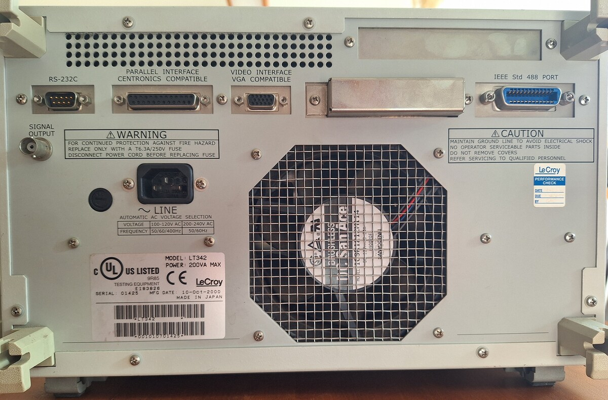
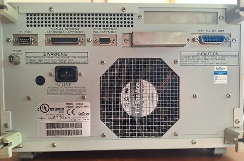
MAINTAIN GROUND LINE TO AVOID ELECTRICAL SHOCK NO OPERATOR SERVICEABLE PARTS INSIDE DO NOT REMOVE COVER REFER SERVICING TO QUALIFIED PERSONNEL, LeCroy PERFORMANCE CHECK, DATE, BY, LINE AUTOMATIC AC VOLTAGE SELECTION VOLTAGE 100-120V AC 200-240V AC FREQUENCY 50/60/400Hz 50/60Hz, MODEL LT342, POWER 200VA MAX
to read or write, the key A itself is not readable; key B is data only). For further information refer to Frequently asked questions or Mifare card manual. Remarks Enabled keys are always read as 00 00 00 00 00 00 Using key B as data area will cause a security gap, due to the fact that it is necessary
Microsoft PEAP,TKIP, WEP. Antenna External 5dBi antenna Throughput 108 Mbps (only with Belkin 54G or 200 ft (60.96 m) – Indoor above router that supports 108 Mbps speed) 54 Mbps 200 ft (60.96 m) – Indoor 11 Mbps 200 ft (60.96 m) – Indoor Certifications Wi-Fi certified Certifications for use by North America
Microsoft PEAP,TKIP, WEP. Antenna External 5dBi antenna Throughput 108 Mbps (only with Belkin 54G or 200 ft (60.96 m) – Indoor above router that supports 108 Mbps speed) 54 Mbps 200 ft (60.96 m) – Indoor 11 Mbps 200 ft (60.96 m) – Indoor Certifications Wi-Fi certified Certifications for use by North America
left side is the internal resistance range (AUTO is the automatic range, 20mR is the 20 mΩ 1 range, 200mR is the 200 mΩ range, 2R is the 2 OHM range, 20R is the 20 OHM range, 200R is 200 OHM range), ② the following part is the voltage range (AUTO is the automatic range, 1V is the 1V range, 10V is the
Für grobe Schätzungen hab ich mal ein Oregon Scientific ESM200 gebraucht gekauft. Macht was es soll und zeigt grob den momentanen Leistungsbedarf in der Wohnung.
ich an der UV nichts Wesentliches verändern, ausser hinter der vorhandenen Herdsicherung die drei RefLeitungen sowie N anzuklemmen. Der Einbau geschieht spannungsfrei. Ausserdem würde ich damit eine mögliche Diskrepanz zwischen dem Zähler und der UV feststellen können, was ich mir aber kaum vorstellen
operating range Plastic sealed type ORDERING INFORMATION [Example] (a) * ) (b(c)– (d) (b) Nominal Voltage Refer to the COIL DATA CHART W : High sensitive type (c) Coil and Contact FunctioWF : High dielectric strength type WD : 2 FORM D (2 MBB type) (d) Enclosure K : Plastic sealed type NoteFor movable and stationary
Life: 25 years at 21°C More Details: On-Line Catalog-Application Manual (Li2FeS ) Shipping: Please refer to PSDS Document Certifications: II 1G 800045 Ex ia IIC Ga Baseefa 14ATEX0107U *All data shown tested at 21°C unless otherwise stated. Milliamp-Hours Capacity Constant Current Discharge to 0.8 Volts AA Lithium AA Alkaline 5000 ) h 4000 A ( 3000 i c 2000 p C 1000 0 0 200 400 600 800 1000 Continuous Discharge Drain (mA) Cells are tested against ANSI-19 C18.3M. (alkaline shown for comparison) Discharge Profile Temperature Effects on Capacity Constant Current Discharge
O 8.0 500 mA O 0.5 , , N 100 mA In0.3 100 mA 4.0 10 mA 0.2 10 mA R ≈ 0 30 mA 0.1 S 0 10 20 50 100 200 500 1 k 2 k 5 k 10 k 20 k 50 k 100 k 10 20 50 100 200 500 1 k 2 k 5 k 10 k 20 k 50 k 100 k f, FREQUENCY (Hz) R S SOURCE RESISTANCE (OHMS) Figure 4. Noise Current Figure 5. Wideband Noise Figure 100
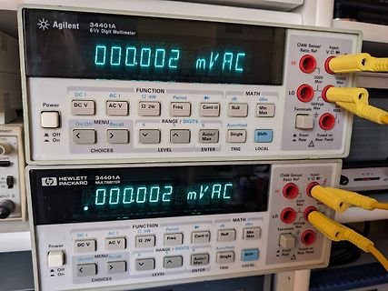
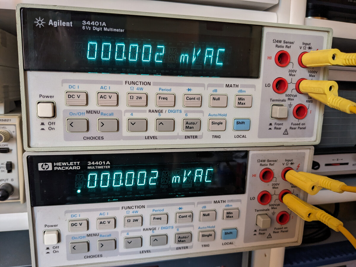
Agilent 34401A 6 1/2 Digit Multimeter 000.002 mV AC Ω4W Sense/Ratio Ref Input V HI 200V Max LO 500Vpk Max 1000V RMS HEWLETT PACKARD 34401A MULTIMETER 000.002 mV AC
PJ401 SW419 6 VIDEO AUX STRAIGHT PROGRAM TONE INPUT R AUDIO L VIDEO CONTROL • Semiconductor Location Ref no. Location D4011 I3 7 Q4005 D4 88 A B C D E F G H I J RX-V667/HTR-6063/RX-A700 1 OPERATION (1) P.C.B. (Side B) 2 49 48 I 3 64 C01 33 1 32 16 17 4 5 6 • Semiconductor Location Ref no. Location Ref
seit fast 10 Jahren in den UP-Dosen meiner Jalousie-Steuerung. https://www.amazon.de/dp/B073QH1XT8?ref=ppx_yo2ov_dt_b_product_details&th=1
? Nein. Die meisten sind Fälschungen. http://lygte-info.dk/review/Power%20Mains%20to%205V%200.6A%20Hi-Link%20HLK-PM01%20UK.html > Das LH05 scheint das einzige Netzteil mit einem guten Datenblatt zu > sein, Aber blödem Widerstand. > oder braucht das IRM-03 wirklich keine zusätzlichen
5.0 V Minimum dV/dt of TxD Input Signal 0.7 1.4 — V/ s 5.0 V pulse TxD Minimum Hold Time for Mode 90 200 — ns V CC=2.7 V to 5.5 V, Change referenced to SD negative clocking edge TxD Minimum Setup Time for Mode –70 –40 — ns V =2.7 V to 5.5 V, Change (Note 2) referenced to SD negative clocking edge TxD Input
geringere Spannung mit viel Strom. Per step down könnte man aus 500W auch 5V mit 100A oder 2.5V mit 200A machen, wenn der step down das schafft. Warum kaufst du nicht gleich ein Netzteil mit einstellbarer Ausgangsspannung aka Labornetzteil ? Ich nutze für grössere Teile https://www.reichelt.de
www.amazon.de/RUZIZAO-Labornetzteil-Digitalanzeige-Stromversorgung-Labornetzger%C3%A4t/dp/B0B5RHTS7W/ref=mp_s_a_1_2_sspa C. D. schrieb im Beitrag #7579632: > Das eine SNT ist im Fundus, das andere eigens bestellt. C. D. schrieb im Beitrag #7580224: > War ein Geschenk eines mir lieben Menschen an
Die Solarthermie ist bei mir recht einfach. Es gibt einen Sonnenkollektor auf dem Dach und einen 200l Warmwasserspeicher im Keller. In den Speicher speist zum einen die Solarthermie ein und zum anderen die Gasheizung. Der Solarteil wird von einer "NAU Solar Control 1020" gesteuert. Ich habe festgestellt
Anlage nach der Idee von Paradigma. In meiner Anlage entstehen Stillstandstemperaturen von weit über 200°C, das würde jedes Glykol ratzfatz zersetzen und ich hätte den Schmodder drin. In der SteamBack ist es VE Wasser und das hinterläßt auch beim Verdampfen keinerlei Rückstände.
durch unser ppm. Das Ding arbeitet mit 12 Volt, nimmt kalt 600mA auf, wenn der Ofen warm ist, dann 200mA. Offensichtlich gibt es eine Nachführung die bei 2,5V ihre Mitte hat darf min 0 Volt sein und max 5V. Ist offensichtlich für 50 Ohm Systeme gebaut, bringt da einen Pegel von 7 dBm. Auch die spektrale
Power supply voltage/current 11 Supply Voltage +12V±5% 12 Working Current ≤600mA Initial ≤200mA stable state Output Characteristics 13 Output waveform Sine wave 14 Output Load Output Load 50Ω 15 Output Level +7±2dBm 16 Harmonic Rejection <-30dBc 17 Stray Wave Rejection <-80dBc
das Bild vom Motor angehängt. Der FU ist der hier: https://www.amazon.de/dp/B0CKX4DSCH?psc=1&ref=ppx_yo2ov_dt_b_product_details Das Bild dazu ist auch mit dabei.
Typennummer deutlicher? > Der FU ist der hier: > > https://www.amazon.de/dp/B0CKX4DSCH?psc=1&ref=ppx_yo2ov_dt_b_product_details Also max 6A. Da kostet ein Sinusfilter von der Stange etwa 200€.
Symbol Parameter Test conditions Min. Typ Max. Unit trr Reverse recovery Tj= 25°C F = 1A dI Fdt = 200 A/µs 41 50 ns time VR=30V RM Reverse recovery Tj= 125°C IF= 100A V R 160V 11.5 15 A current dIF/dt = 200 A/µs tfr Forward recovery Tj= 25°C F = 100A dIF/dt = 200 A/µs 800 ns time VFR = 1.1 x VFmax V FP Forward recovery Tj= 25°C F = 100A dIF/dt = 200 A/µs 2.5 V voltage 2/5 ® STTH20002TV Fig. 1: Peak current versus duty cycle (per diode). Fig. 2-1: Forward voltage drop versus forward current (typical values, per diode). IM(A) 600 IFM (A) 200 180
Leistungs-MOSFET mit erweiterten FBSOA Bereich im SOT-277 Leistungsgehäuse und Schraubanschlüsse in Frage (IXTN200N10L2): Z.B der hier: https://www.mouser.ca/ProductDetail/IXYS/IXTN200N10L2?qs=sGAEpiMZZMvplms98TlKY407BghGkTxJb5MrGNSCSKc%3D https://www.mouser.ca/datasheet/2/240/media-3321296.pdf Als Kühlkörper selektierte ich drei 200W Arctic Freeze Kühlaggregate die mit den jeweiligen zu erwartenden 200W spielend fertig wurden, wie sich durch Testen bestätigen ließ. Als Strommesswiderstände selektierte ich Vierleiter Widerstände
einem guten Netzteil überbrückt werden können. Naja, gefordert sind 17ms unter Volllast. Da sind 200ms schon weit entfernt von.
2Fwww.golem.de%2Fnews%2Fumstrittene-studie-warum-manche-stromzaehler-extrem-falsch-messen-1703-126656.html&referer=https%3A%2F%2Fwww.google.com%2F https://www.americanexpress.com/de-de/amexcited/explore-all/technology/smart-meter-21428 "Mittlerweile haben die Herstellerfirmen nachgerüstet. Geräte mit Shunt
mVrms n CL= 1.0 mF − 126 − CL= 100 mF − 56 − LP2951A/LP2951AC Only Reference Voltage (T = 25°C) V V A ref LP2951C/LP2951C−XX/NCV2951C* 1.210 1.235 1.260 LP2951AC/LP2951AC−XX/NCV2951AC* 1.220 1.235 1.250 Reference Voltage AT = −40 to +125°C) V ref V LP2951C/LP2951C−XX/NCV2951C* 1.200 − 1.270 LP2951AC/LP2951AC−XX/NCV2951AC* 1.200 − 1.260 Reference Voltage AT = −40 to +125°C) V ref V O = 100 mA to 100 mA,in = 23 to 30 V LP2951C/LP2951C−XX/NCV2951C* 1.185 − 1.285 LP2951AC/LP2951AC−XX/NCV2951AC* 1.190 − 1.270 Feedback Pin Bias
interrupt Priority bit 3 PT1 Refer to PT1H for priority level. External interrupt 1 Priority bit 2 PX1 Refer to PX1H for priority level. 1 PT0 TimRefer to PT0H for priority level.it 0 PX0 External interrupt 0 Priority bit Refer to PX0H
Ich nutze u.a. https://www.amazon.de/dp/B0C89CZMR5?ref=ppx_yo2ov_dt_b_product_details&th=1 mit ioBroker. Die lassen sich dan Tasmota aber auch direkt ansprechen.
Messen und Schalten geht mit FritzDect200/210 - besonders einfach bei schon vorhandener Fritzbox.
10 G S A I T N E20 E C G R A 10 P L O 10 V GAIN = 100, 1,000 GAIN = 1000 BW LIMIT 7 0 0 0 1 - –400 –200 0 200 400 - 1 10 100 1k 10k 100k 5 7 FREQUENCY (Hz) 0 INPUT OFFSET CURRENT (pA) 0 0 Figure5.TypicalDistributionofInputOffsetCurrent Figure8.VoltageNoiseSpectralDensityvs.Frequency(G=1−1000) Rev. H |

 Bild
Bild
 Bild
Bild
 Bild
Bild
 Bild
Bild