-
Thread
HP461 - Verstärker 20/40dB
Bernhard S. schrieb im Beitrag #8003115: > as sieht doch nicht vollkommen verkehrt aus Ich kann im Diagramm keine Verstärkung erkennen, wenn die Linie hauptsächlich im Bereich um -40dB (minus!) verläuft.
-
Thread
Atmel Fingerchip —> welches Flexkabel?
Der Firmengründer begann mal mit einer digitalen Morsetaste daher der Name: "1972 DigiKey begins as a small mail-order company when Dr. Ron Stordahl began selling the leftover parts to a digital electronic keyer kit (the Digi-Keyer)" https://www.digikey.de/en/products/detail/molex/0150310421/16591764
-
Thread
Splinter - Padauk Programmer mit CH32V003
Steckbrett oder auf ein entsprechend gerouetetes Board stecke kann. Auf github gibst du an, dass "rvusb as a later step" angedacht ist, auch darauf bin ich sehr gespannt. :-) auch wenn ich da mittlerweile meinem Clone des EASY-PDK verhaftet bin (einfach weil in der Handhabung pragmatischer). Vllt. wird
-
Thread
433MHz Heizkostenverteiler auslesen
Bernhard S. schrieb im Beitrag #8002494: > Verschlüsselung: AES-128 Hast du denn den Code?
Die bisherige Implementierung für Wasseruhren funktioniert ohne AES-Schlüssel, der ist vielleicht nur Optional. Es gibt diverse Projekte auf Github zur Integration von Gas- oder Wasserzählern in ESPHome oder Home Assistant. Erstmal aber müssen ein paar Daten ankommen
-
Thread
Einstieg in PIC mit MPLAB X und Snap Adapter
RTC_PITEN_bm; // 62ms period, enable PIT EVSYS.ASYNCCH0 = EVSYS_ASYNCCH0_PORTA_PIN1_gc; // PA1 as event generator EVSYS.ASYNCUSER0 = EVSYS_ASYNCUSER0_ASYNCCH0_gc; // TCB as event user TCB0.CTRLB = TCB_CNTMODE_PW_gc; // pulse-width measurement TCB0.EVCTRL = TCB_CAPTEI_bm
-
Thread
Monostufe mit Retrigger für Arduino
Sechster Druck: Reset (weil man sich verdrückt hat). Das wäre die Bedienung des Ansmann Timers AES-1, die sehr praxisgerecht ist: Erster Tastendruck Ein für 15 min, jeder weitere 30 - 60 - 2h - 4h - 8h. Der nächste Tastendruck lässt die 15 min LED blinken und nach ein paar Sekunden schaltet das Gerät
der abgelaufene Countdown dann tun soll, für Schuko muss man nicht mal mehr basteln... Ansmann AES1 Timer-Steckdose https://amzn.eu/d/03rpAFFw mfg mf
-
Thread
Programmieren mit KI
schrieb im Beitrag #8005151: > ein MS Konto für die KI als Vorraussetzung There's no such thing as a free lunch!
Alexander S. schrieb im Beitrag #8005576: > As a result, I do not recommend you use this code! None of it > has been validated for correctness. Und trotzdem hat er es zum Widerkäuen auf Github belassen. Es beginnt..
-
Thread
DDR4 im Weltraum, neuer 5V-PIC32, LoRA für Drohnen uvam
150Hz) • FrSky R9: A commercial alternative that hasn't achieved the same market penetration as ExpressLRS • Custom implementations: Various research projects and specialized applications have developed proprietary LoRa protocols optimized for specific use cases [/c] Interessant sind
Spezifischerweise vermeldet man, dass die neue Einheit pinkompatibel mit ihren AVR-Kolleginnen ist: [c] As part of the company’s unified MCU strategy, PL10 devices offer pin-to-pin compatibility with AVR® MCUs. [/c] 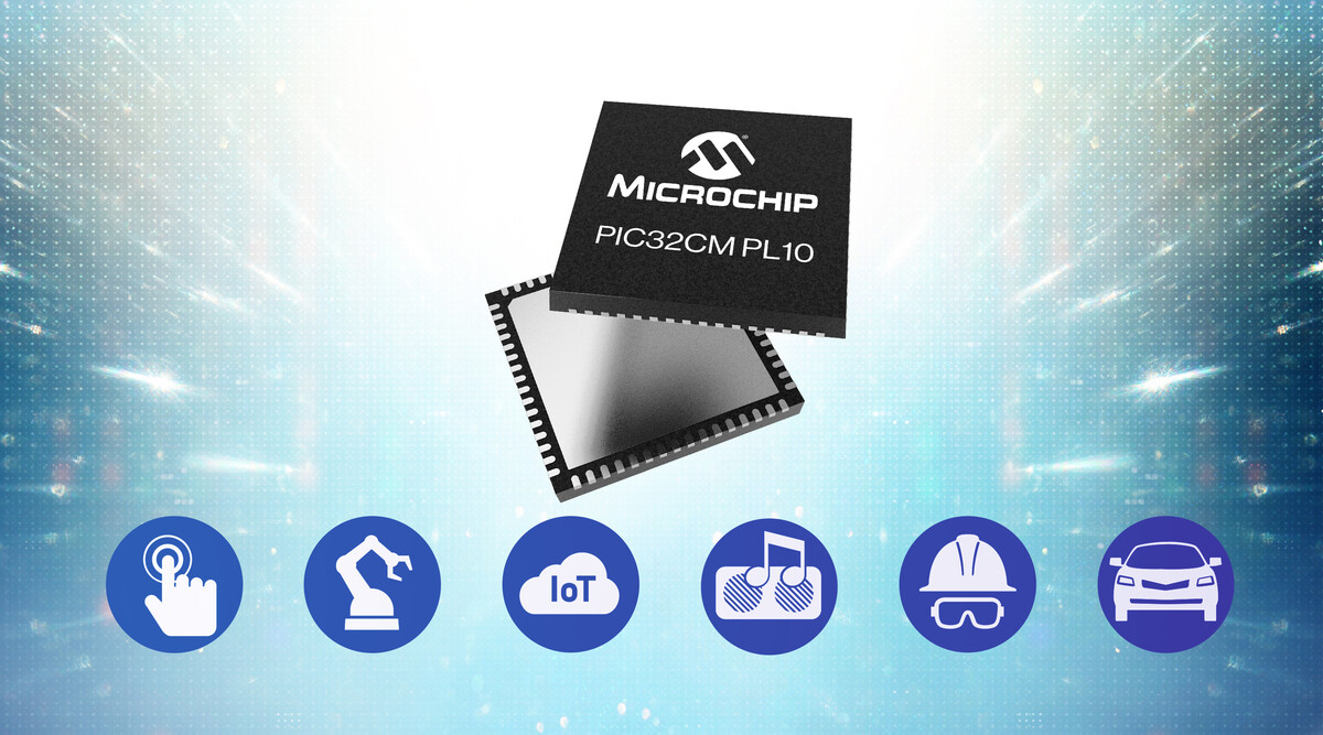 Bildquelle: Microchip. Die eingangs erwähnte 5 V-Fähigkeit
-
 Bild
Bild
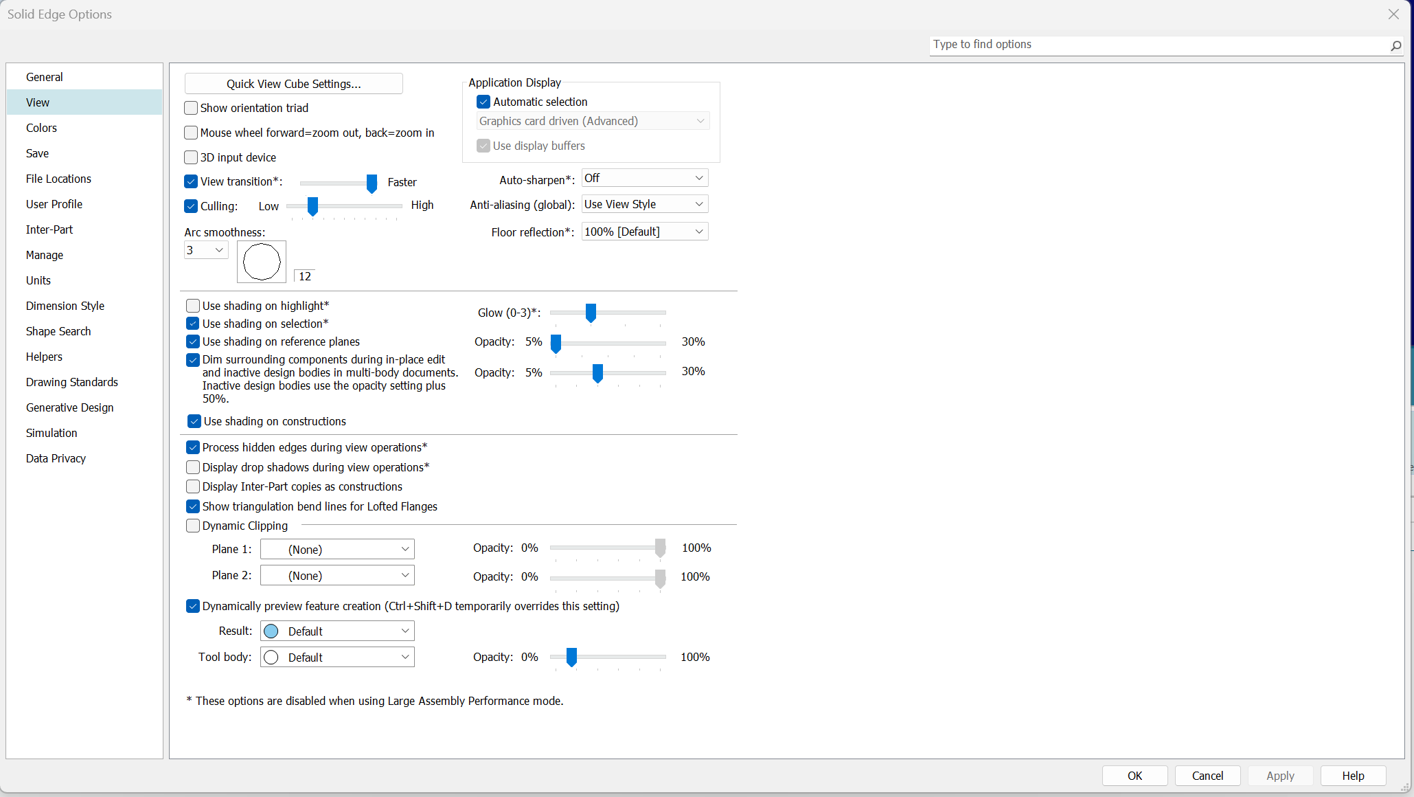
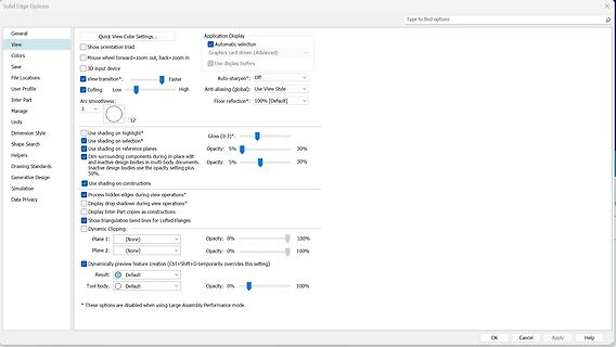
Einstellungen für Solid Edge Optionen
edges during view operations* Display drop shadows during view operations* Display Inter-Part copies as constructions Show triangulation bend lines for Lofted Flanges Dynamic Clipping Plane 1: (None) Opacity: 0% 100% Plane 2: (None) Opacity: 0% 100% Dynamically preview feature creation (Ctrl+Shift+D temporarily
-
Thread
Si5351-Inizialisierung
habe. musst du auch nicht, du kannst das auch bequem online erledigen: https://godbolt.org/z/MjE8asPqs
-
 Bild
Bild
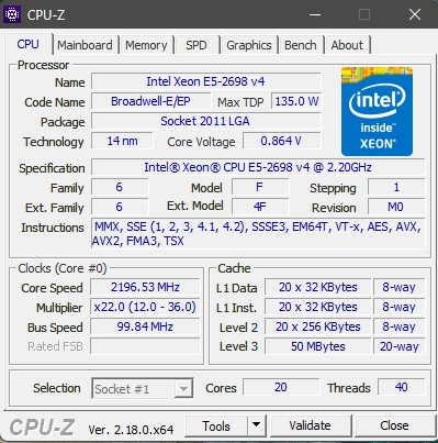
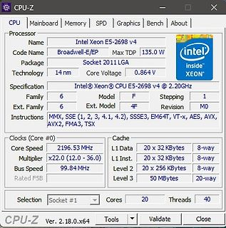
CPU-Z Screenshot eines Intel Xeon Prozessors
135.0 W Socket 2011 LGA 14 nm Core Voltage 0.864 V MMX, SSE (1, 2, 3, 4.1, 4.2), SSSE3, EM64T, VT-x, AES, AVX, AVX2, FMA3, TSX 2196.53 MHz x22.0 (12.0 - 36.0) 99.84 MHz L1 Data 20 x 32 KBytes 8-way L1 Inst. 20 x 32 KBytes 8-way Level 2 20 x 256 KBytes 8-way Level 3 50 MBytes 20-way Cores 20 Threads 40
-
 Bild
Bild
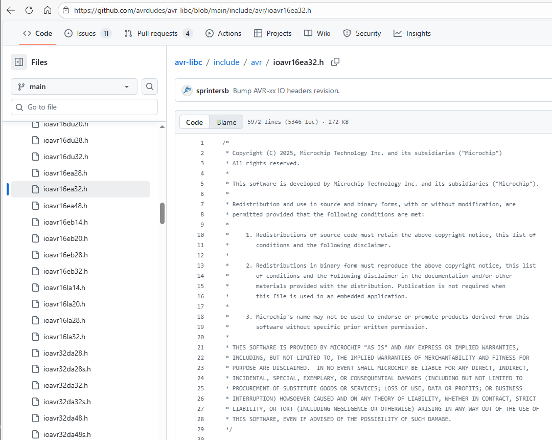
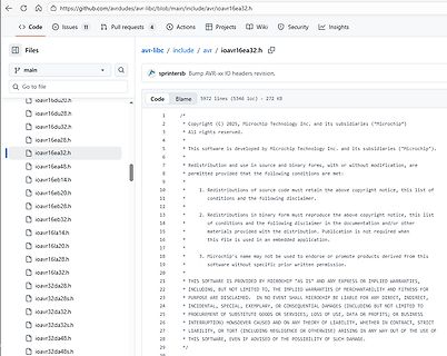
GitHub Code-Ansicht einer Header-Datei
when * this file is used in an embedded application. * * THIS SOFTWARE IS PROVIDED BY MICROCHIP "AS IS" AND ANY EXPRESS OR IMPLIED WARRANTIES, * INCLUDING, BUT NOT LIMITED TO, THE IMPLIED WARRANTIES OF MERCHANTABILITY AND FITNESS * FOR A PARTICULAR PURPOSE ARE DISCLAIMED. IN NO EVENT SHALL MICROCHIP
-
Thread
c# Lade- Entladeprogramm für Akkus
port; // dann: private void InitSerial() { try { var portName = cboPorts.SelectedItem as string ?? throw new InvalidOperationException("Invalid COM-port"); _port = new SerialPort(portName, 115200, Parity.None, 8, StopBits.One); _port.DataReceived += SerialPort_DataReceived;
-
Thread
Programm für Rapsberry PI Pico mit RP2040
increases on every button press and resets after 8. Each time the button is pressed, the output is toggled as many times as the current counter value. Here is a very basic MicroPython example for the Raspberry Pi Pico that should be easy to understand: [c] #define BUTTON_PIN 14 #define OUTPUT_PIN 15
-
 Bild
Bild
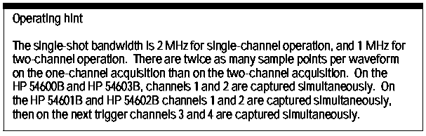
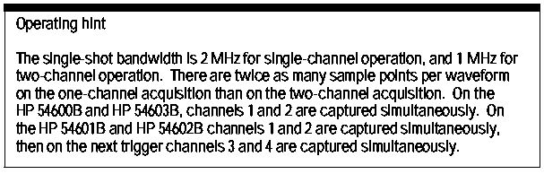
Text mit Bedienhinweisen für Oszilloskope
bandwidth is 2 MHz for single-channel operation, and 1 MHz for two-channel operation. There are twice as many sample points per waveform on the one-channel acquisition than on the two-channel acquisition. On the HP 54600B and HP 54603B, channels 1 and 2 are captured simultaneously. On the HP 54601B and
-
 Bild
Bild
Datenblatt-Ausschnitt eines X04 SCRs
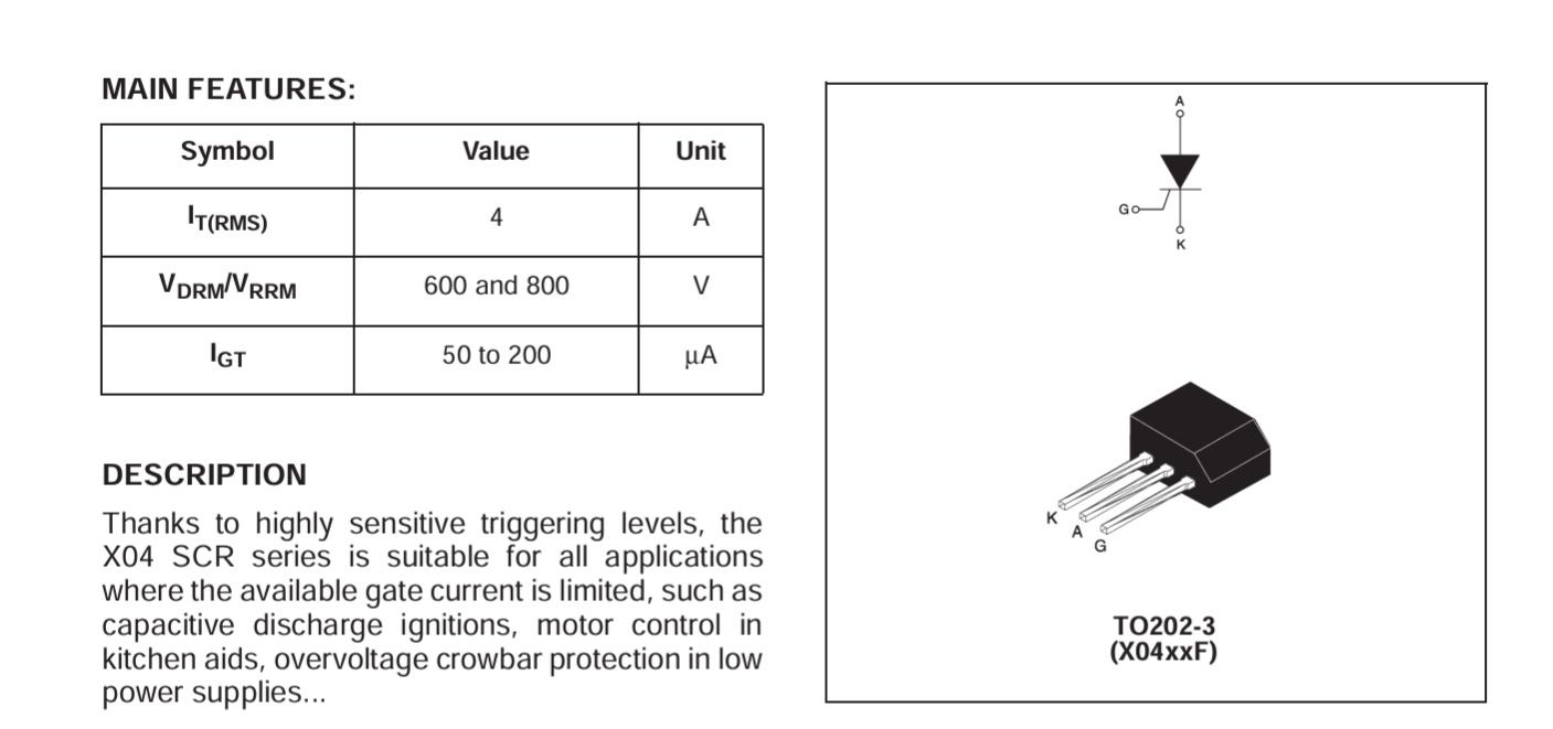
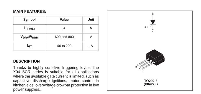
X04 SCR series is suitable for all applications where the available gate current is limited, such as capacitive discharge ignitions, motor control in kitchen aids, overvoltage crowbar protection in low power supplies... K A G TO202-3 (X04xxF)
-
Thread
Raspberry Pi-USB-Stick, Rust-Update, Spaß mit 3D-Druckern uvam
significant advantages to doing this: for short periods, the sequential write speed can be almost as fast as USB 3.0 will go. This cache does, however, make benchmarking challenging. For this reason, the USB 3.0 performance figures we quote are sustained figures, [/c] Die folgenden Abbildungen
-
 Bild
Bild
Programmübersicht der AMPER 2026 Messe
presentation formats. March 17: SMART INDUSTRY - AMPER EDITION The all-day program will cover topics such as industrial artificial intelligence, production automation, maintenance efficiency, documentation digitization, energy savings. Look forward to specific case studies from Czech and foreign companies.

-
Thread
Keine SSH-Verbindung zum Raspi mit FileZilla möglich
Putty-Gen erzeugst), sondern um die Vereinbarung eines (symmetrischen) _Sitzungsschlüssels_ (z.B. 128-Bit-AES), den beide Parteien zu Anfang aushandeln. Für dieses Aushandeln (https://de.wikipedia.org/wiki/Diffie-Hellman-Schl%C3%BCsselaustausch) haben Filezilla und der neue Raspi kein gemeinsames Verfahren
-
Thread
ESP32-E22 offiziell, neuer Mikrocontroller von WCH, Raspberry Pi-Tethering uvam
Intention, dass der E22 explizit als Funk-Coprozessor für aller Herren Systeme vorgesehen ist: [c] As an RCP, ESP32-E22 manages the complete Wi-Fi and Bluetooth protocol stacks internally—including security, authentication, scanning, roaming, and Bluetooth host functionality. This architecture allows
pair ESP32-E22 with Espressif’s own SoCs or third-party processors through high-speed interfaces such as PCIe 2.1, and SDIO 3.0, depending on system needs. [/c] 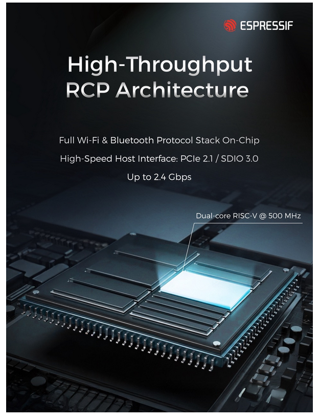 Bildquelle: https://www.espressif.com/en/news/ESP32_E22_Announcement Leider gilt, dass zum Zeitpunkt der
-
Thread
ATmega328p reset pin chip intern auf low?
mich das. Aus dem Datenblatt, Abschnitt 1.1.5: > If the RSTDISBL Fuse is programmed, PC6 is used as an I/O pin. Aus dem Datenblatt, Abschnitt 14.3.2: > When the RSTDISBL Fuse is programmed, this pin functions as a normal I/O pin, https://ww1.microchip.com/downloads/aemDocuments/documents/MCU08
#7996724: > Aus dem Datenblatt, Abschnitt 1.1.5: >> If the RSTDISBL Fuse is programmed, PC6 is used as an I/O pin. Oh danke. Ich habe offensichtlich ein älteres Datenblatt (7810D–AVR–01/15), da ist nur von Input die Rede. Die Fuse macht den PC6 zum Reset und der Reset funktioniert ja auch, nur halt
-
Thread
TV mit "Korona-Effekt"
auf. Einfach beim schauen mal auf den Himmel achten... Rene K. schrieb im Beitrag #7997002: > as liegt daran das ein SAT Transponder nur > 44Mbit schafft (mit Schutzbit kommen effektiv nur 36MBit an Daten an). > Für UHD ist das schon etwas eng - das wird sich auch nicht ändern - aus > diesem
-
Thread
SMD-MSOP10-Platinprojekt in Eigenfertigung mit bestelltem Belichtungsfilm
so nicht beachtet: [pre] The following high di/dt loops of different topologies should be kept as tight as possible to reduce inductive ringing: • In SEPIC configuration, the high di/dt loop contains the power MOSFET, sense resistor, output capacitor. [/pre] Und natürlich ist auch die Spule
nicht beachtet: > [pre] > The following high di/dt loops of different topologies > should be kept as tight as possible to reduce inductive > ringing: > • In SEPIC configuration, the high di/dt loop contains > the power MOSFET, sense resistor, output capacitor. > [/pre] > Und natürlich ist auch
-
 Bild
Bild
Datenblatt mit technischen Zeichnungen und Diagramm eines Cryocoolers
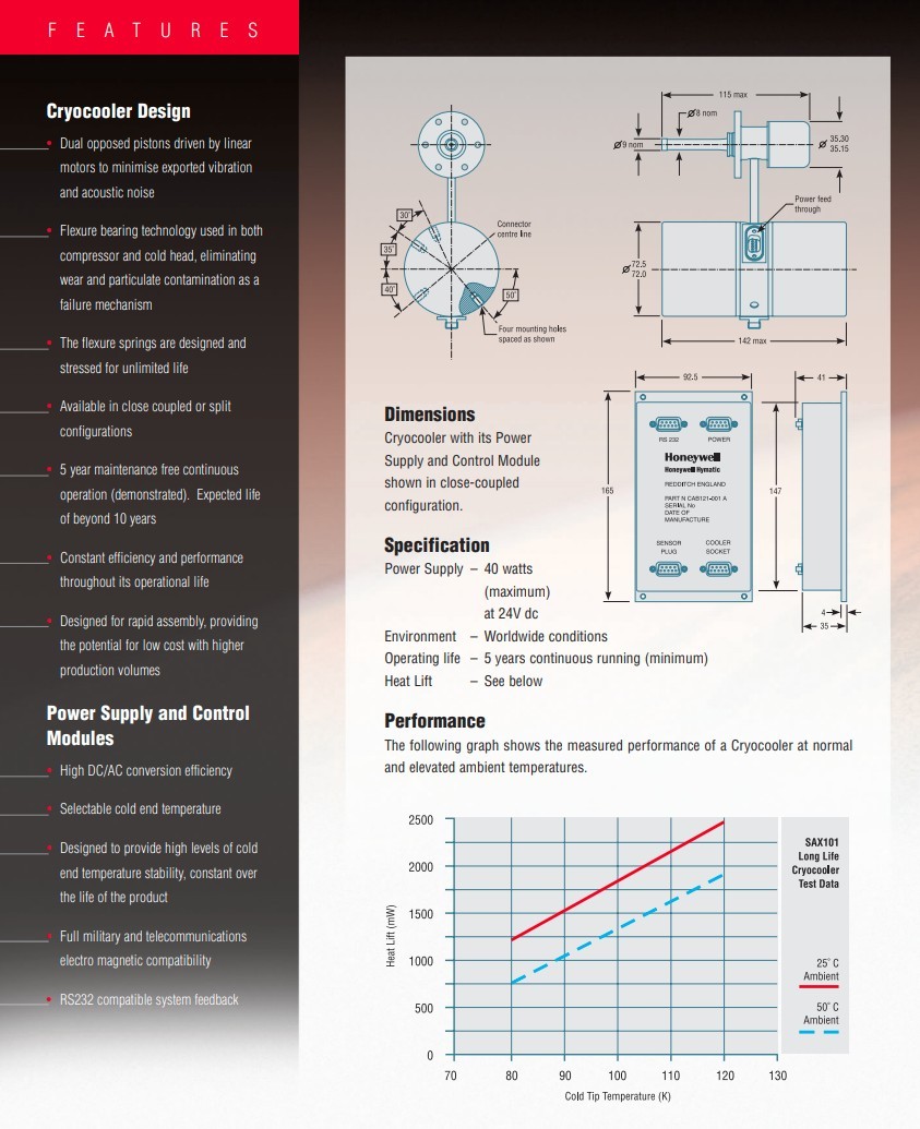
bearing technology used in both compressor and cold head, eliminating wear and particulate contamination as a failure mechanism The flexure springs are designed and stressed for unlimited life Available in close coupled or split configurations 5 year maintenance free continuous operation (demonstrated). Expected
-
 Bild
Bild
Diagramm zur Zündzeitsteuerung eines CDI-Systems
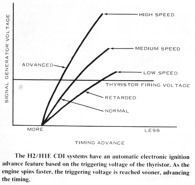
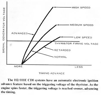
an automatic electronic ignition advance feature based on the triggering voltage of the thyristor. As the engine spins faster, the triggering voltage is reached sooner, advancing the timing.
-
Thread
Micropython Wetterstation
UTF-8 als verwendeten Zeichensatz anzugeben (besser wär’s noch auf HTTP-Ebene), um dann das Zeichen „as is“, also ohne die °-Umschreibung benutzen zu können.
?) [code]#!/python # vim: fileencoding=utf-8: ts=4: sw=4: expandtab: from machine import freq as cpufreq from time import ticks_us,ticks_diff MEG = const(1_000_000) SIZE = const(100_000) # zwei mal genutzt @micropython.viper def memcpyB(src: ptr8, dest: ptr8, size:int): idx: int =