-
Datei
PWM_Modulation_Code.txt
uint8_t LEDnummer = 0; int LEDwert[4]; //Binärwert der jeweiligen LED int PWMstatus[4]; // aktueller Modulationsgrad der LED uint8_t PWMtime = 0; uint8_t PWMlevel = 0; uint8_t LEDon = 15; uint8_t LEDoff[3]; uint8_t LEDoff25 = 0; uint8_t LEDoff50 = 0; uint8_t LEDoff75 = 0; uint16_t ADC_Taste = 1023; uint8_t status = 0; uint8_t Tasterdelay = 0; int main(void) { LEDwert[0] = 1; LEDwert[1] = 2; LEDwert[2] = 4; LEDwert[3] = 8; PWMstatus[0] = 4; PWMstatus[1] = 4; PWMstatus[2] = 4; PWMstatus[3] = 4; LEDoff[0] = 0; // LEDs bei Tastgrad 25% ausschalten LEDoff[1] = 0; // LEDs bei Tastgrad 50% ausschalten
in „PWM-Modulation“ · Mikrocontroller und Digitale Elektronik ·
-
Datei
nex_4_pwm.vhd
); end nex_4_pwm; architecture Behavioral of nex_4_pwm is signal pwm_zaehler: unsigned(15 downto 0):=(others => '0'); begin led <= sw; RGB1_Red <= '1' when pwm_zaehler <= unsigned(sw); RGB1_Green <= '1' when pwm_zaehler <= unsigned(sw); RGB1_Blue <= '1' when pwm_zaehler <= unsigned(sw); process begin wait until rising_edge(clk); pwm_zaehler <= pwm_zaehler +1; end process; end Behavioral;
-
Datei
FastSoftPWM.asm
.include "m1284pdef.inc" .equ wt_enable=1 .equ eff1=1 .equ eff2=1 .equ eff3=1 .equ eff4=1 .equ eff5=1 .equ eff6=1 .equ eff7=1 .equ eff8=1 .equ eff9=1 .equ eff10=1 .equ eff11=1 .equ eff12=1 .equ eff13=1 .equ eff14=1 .equ eff15=1 .equ eff16=1 .equ eff17=1 .equ eff18=1 .equ eff19=1 .equ timer=21 .equ leds=256 .equ output_bits=10 ;not to be changed without major code adaption! .equ ul=53 ;upper limit of LED intensity, depends on the number of entries in the intensity lookup table .equ smooth=1 .include "convert_macro.asm" ;macros for translating logical LED numbers into real "addresses" at the driver
-
Datei
stm32-pwm.c
/* USER CODE BEGIN Header */ /** ****************************************************************************** * @file : main.c * @brief : Main program body ****************************************************************************** * @attention * * <h2><center>© Copyright (c) 2021 STMicroelectronics. * All rights reserved.</center></h2> * * This software component is licensed by ST under BSD 3-Clause license, * the "License"; You may not use this file except in compliance with the * License. You may obtain a copy of the License at: * opensource.org/licenses/BSD-3-Clause * *********************
in „PWM-Signal mit STM32 messen“ · Mikrocontroller und Digitale Elektronik ·
-
Datei
PWM-TEST_886.asm
init bank0 clrf PORTA clrf PORTB clrf PORTC bank1 movlw b'11111001' movwf TRISC ; RC1/2 = Ausgang (PWM) return ;****************************************************************** setpwm bank1 movlw 0xFF ; frequenzbestimmend movwf PR2 clrf PWM1CON clrf ECCPAS bank0 movlw b'00000101' ; TMR2 on, Prescaler = 4 movwf T2CON movlw b'00001100' ; PWM-Mode mit Standardauflösung 10 bit movwf CCP1CON movwf CCP2CON nop ; Initialwerte für die clrf CCPR1L ; duty cycle-Register clrf CCPR2L return ;*******************************************************
in „PIC16F886 PWM-Programm läuft nicht“ · Mikrocontroller und Digitale Elektronik ·
-
Datei
tb_pwm2.vhd
LIBRARY ieee; USE ieee.std_logic_1164.ALL; ENTITY tb_pwm2 IS END tb_pwm2; ARCHITECTURE behavior OF tb_pwm2 IS -- Component Declaration for the Unit Under Test (UUT) COMPONENT pwm2 PORT( CLK : IN std_logic; SW : IN std_logic_vector (5 downto 0); PWM_Value
in „DC Motor, PWM, Drehrichtung, Drehzahl“ · FPGA, VHDL & Co. ·
-
Datei
PWM-diff-20210120.diff
diff -r -u 1.42m-20210120/tools_signal.c dev-m/tools_signal.c --- 1.42m-20210120/tools_signal.c 2021-01-12 10:29:02.000000000 +0100 +++ dev-m/tools_signal.c 2021-01-21 18:27:34.000000000 +0100 @@ -274,6 +274,7 @@ uint16_t Step2; /* step size */ uint16_t Temp; /* temporary value */ uint32_t Value; /* temporary value */ + uint32_t CycleLenUs; /* length of one cycle in us */ /* local constants for Flag (bitfield) */ #define RUN_FLAG 0b00000001 /* run / otherwise end */ @@ -435,6 +436,7 @@ Value = CPU_FREQ * 50; /* scale to 0.01Hz and /2 */ Value /= Prescaler; Step = 2; /* 2 decimal places */ + CycleLenUs
-
Datei
ADC_PWM_2.c
/Messung starten //Warten auf Ergebnis ADCSRA |= (1 << ADSC); while (ADCSRA & (1 << ADSC)); } void pwm_init(){ //Ausgänge setzen DDRA |= (1 << PA6) | (1 << PA7) | (1 << PA5); DDRB |= (1 << PB2); //Timer 0 (8 Bit) //Löschen von Bits: OC0A/OC0B Bit 7 + 6 //Art der Wellenform erzeugung: PWM, Phase Correct
in „ADC und PWM am ATtiny84“ · Mikrocontroller und Digitale Elektronik ·
-
Datei
PWM_Dimmer_entprellt.txt
(Timer1) TIMSK = 1<<OCIE1A; // (Timer1) LED_DDR = 1<<LED0; KEY_PORT |= (1<<KEY0); // Pullup on /* PWM für Dimmer */ TCCR0A = ( 1 << COM0A1 ) | ( 1 << WGM00 ) | ( 1 << WGM01 ); // Clear OC0A/OC0B on Compare Match // Fast PWM , TOP = 0xFF TCCR0B = ( 1 << CS01 ) | ( 1 << CS00 ); // Mode: Normal | F_Proz
in „Eintastendimmer und Taster Entprellung“ · Mikrocontroller und Digitale Elektronik ·
-
Datei
PWM_Dimmer_entprellt.txt
From prescaler) OCR0A = 0; // LED aus sei(); for(;;){ // main loop if( (get_key_short( 1<<KEY0 ))) if(pwm > 0) pwm = 0; else pwm = 255; if( get_key_long_r( 1<<KEY0 ) || get_key_rpt_l( 1<<KEY0 )) { pressed = 1; if( direction ) { if( pwm < 255 ) ++pwm; } else { if( pwm > 0 ) --pwm; } } else if( pressed ) { pressed = 0; direction = 1 - direction; } OCR0A = pwm; //_delay_ms(10); } return 0; }
in „Eintastendimmer und Taster Entprellung“ · Mikrocontroller und Digitale Elektronik ·
-
Datei
pwm_sync_2.c
#include <avr/io.h> #include <avr/interrupt.h> #include "usbdrv.h" int volatile steps = 0; static uchar replyBuf[16]; ISR(TIMER2_OVF_vect){ steps++; PORTB ^= _BV(PB1); TCNT2 = 200; } ISR(INT1_vect){ TCCR2 &= ~_BV(CS20) & ~_BV(CS21) & ~_BV(CS22); sprintf(replyBuf, "Steps: %i", steps); } USB_PUBLIC uchar usbFunctionSetup(uchar data[8]){ usbRequest_t *rq = (void *)data; switch(rq->bRequest){ case 1: TCCR2 |= _BV(CS22); return 0; case 0: // send data to PC usbMsgPtr = replyBuf; return sizeof(replyBuf); } return 0; } int main(){ TIMSK |= _BV(TOIE2); TCNT2 = 200; TCCR2 &= ~_BV(CS20) & ~_BV(CS21) & ~_BV
in „Timer2 wie Timer0 nutzen“ · Mikrocontroller und Digitale Elektronik ·
-
Datei
MD_SOFT_PWM.h
with specific frequency (can shared as system timer, no influence!) */ volatile uint8_t *cnt_reg_softPWM; inline MD_soft_PWM_init(uint8_t *counter_reg, uint8_t timer_pre_init) { //@fct: Init the soft pwm with timer/counter register or init a 1khz timer (check frequency and prescaler!) //is timer init always init? if (timer_pre_init) cnt_reg_softPWM = counter_reg; else { //Timer init with 1ms/ovf (only for timing, e.g can dimming (soft) TCCR0B |= (1<<CS01)|(1<<CS00); //prescaler 64 ==> freq. is 1khz cnt_reg_softPWM = &TCNT0; } } static void MD_soft_PWM_HandlePin
in „FULL NMRA DCC Library, Encoder, Generator, Bremsmodul“ · Projekte & Code ·
-
Datei
PWM_Arduino-Leonardo.ino
otherwise timer remains stopped } OCR1A = periode; // TOP Wert bestimmt Auflösung und mit Prescaler den PWM Takt bzw. die Periode OCR1B = duty; // Pulsweite, OCR1B <= OCR1A } void stopTimer1 () { TCCR1B = 0; // Reset, stop timer first TCCR1A = 0; // Reset TIMSK1 = 0; // Reset (disable Timer Compare Interrupts
in „Präzise Pulse aus Arduino Leonardo“ · Mikrocontroller und Digitale Elektronik ·
-
Datei
PWM_Arduino-Leonardo.ino
: break; // otherwise timer remains stopped } // TOP Wert bestimmt Auflösung und mit Prescaler den PWM Takt bzw. die Periode OCR1A = periode; OCR1B = duty; // Pulsweite, OCR1B <= OCR1A } void stopTimer1 () { TCCR1B = 0; // Reset, stop timer first TCCR1A = 0; // Reset TIMSK1 = 0; // Reset (disable Timer
in „Präzise Pulse aus Arduino Leonardo“ · Mikrocontroller und Digitale Elektronik ·
-
PDF
PWM-Halbbruecke_Sch.pdf
R17 R7 1k 10k U2B R18 R19 4 D2 10.02R 1 0.02R 5 6 1 2 & 74HC00 gruen U2A D3 1 1 2 2 & 3 74HC00 rot PWM-Halbbrücke
in „Motoransteuerung - 24vdc / max. 500W“ · Analoge Elektronik und Schaltungstechnik ·
-
PDF
EVG_Dimmer_PWM.pdf
LED D +5V +12V 1k N +5V 560 N PC817 LED Vf: 1,2V G G Ergibt mit Rv 330 Ohm: R23 D2 R26 D4 - bei 3,3V-PWM --> 6,4mA LED-Strom - bei 5V-PWM --> 11,5mA LED-Strom F 1 A u C F 7 A 1 GND 1 C GND U1 PC817 U7 R1 U5A PC817 PWM_1 330 1 4 PWM_5 R17 1 4 U9A LM358 330 LM358 PWM-Frequenz: R9 R13 R21 R24 1kHz ... 20kHz
in „Schaltplankontrolle EVG-Dimmer -PWM, OpAmp und Ladungspumpe“ · Analoge Elektronik und Schaltungstechnik ·
-
PDF
Maxim_PWM_Simu.pdf
EESim DCDC Design Requirements changed 2.0 Design Requirements Parameter Value Minimum Input Voltage 29V Maximum Input Voltage 40V Nominal Input Voltage 32V Input Voltage Ripple 1% Output Voltage 24V Output Current 4.5A Output Voltage Ripple 1% Load Step Start Current 4.5A Load Step Current 2.25A Load Step Edge Rate 5A/us Output Voltage Load Step Over/Undershoot 3% Performance Priority Balance Efficiency and Size BOM Priority Performance Switching Frequency 550kHz Lock Switching Frequency Not locked Output Capacitor Type Ceramic Ambient Temperature 25°C Inductor Current Ratio(LIR) 0.3 Soft Stop
in „Spule mit 4 Anschlüssen“ · Analoge Elektronik und Schaltungstechnik ·
-
 Bild
Bild
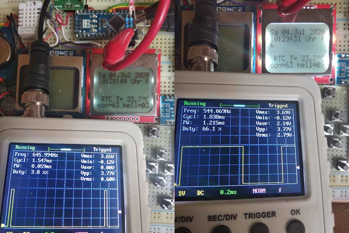
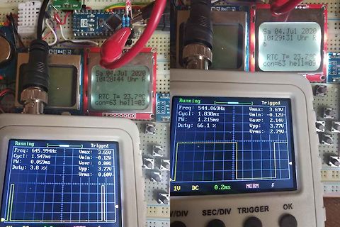
Messaufbau mit Display und Oszilloskop-Anzeige
Sa 04.Jul 2020 10:28:44 Uhr R RTC T= 23.7°C con=63 hell=03 Running Freq: 645.994Hz Cycl: 1.547ms PW: 0.059ms Duty: 3.8 % Triggered Umax: 3.65V Umin: -0.12V Uavr: 0.00V Upp: 3.77V Urms: 0.60V 1V DC 0.2ms NORM f
in „Bitte was bedeutet Uce und Ucb?“ · Analoge Elektronik und Schaltungstechnik · · Fotos
-
 Bild
Bild
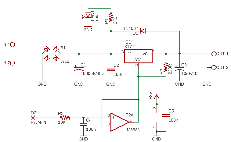
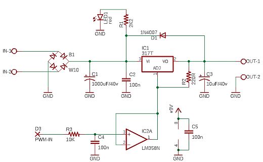
Schaltplan eines Netzteils mit Spannungsregler und Operationsverstärker
C1 1000uF/40v GND C2 100n IC1 317T VI ADJ VO 2 R2 220R C3 10uF/40v OUT-1 OUT-2 GND +9V C5 100n 4 D3 PWM-IN R3 10K C4 100n 3 + IC2A LM358N 2 1 GND
in „Suche kleines Modul/Breakout: DCDC von Arduino steuerbar“ · Mikrocontroller und Digitale Elektronik · · Schaltpläne
-
 Bild
Bild
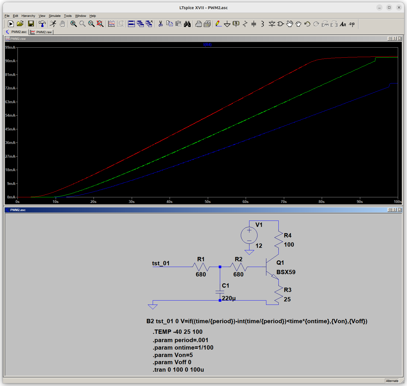
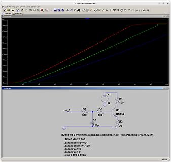
LTspice Simulation Schaltplan und Stromverlauf
LTspice XVII - PWM2.asc File Edit Hierarchy View Simulate Tools Window Help 9mA 81mA 72mA 63mA 54mA 45mA 36mA 27mA 18mA 9mA 0mA 0s 10s 20s 30s 40s 50s 60s 70s 80s 90s 100s V1 R4 12 100 Q1 BSX59 R1 R2 680 680 tst_01 C1
in „Tankanzeige eines E36 mit Mikrocontroller Steuern“ · Fahrzeugelektronik · · Screenshots
-
 Bild
Bild
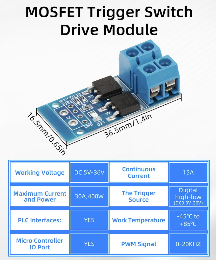
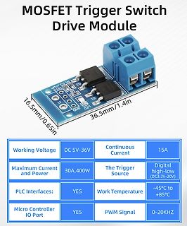
MOSFET Trigger Switch Drive Module mit technischen Daten
MOSFET Trigger Switch Drive Module 16.5mm/0.65in 36.5mm/1.4in R1 R3 PWM Q2 LED1 LED2 LED3 GND Working Voltage DC 5V-36V Continuous Current 15A Maximum Current and Power 30A,400W The Trigger Source Digital high-low (DC3.3V-20V) PLC Interfaces: YES Work Temperature -45°C to +85°C Micro Controller IO Port YES PWM Signal 0-20KHZ
in „Mosfet Modul mit PWM ansteuern MKS GEN_L V2.1“ · Mikrocontroller und Digitale Elektronik · · Platinenfotos
-
 Bild
Bild
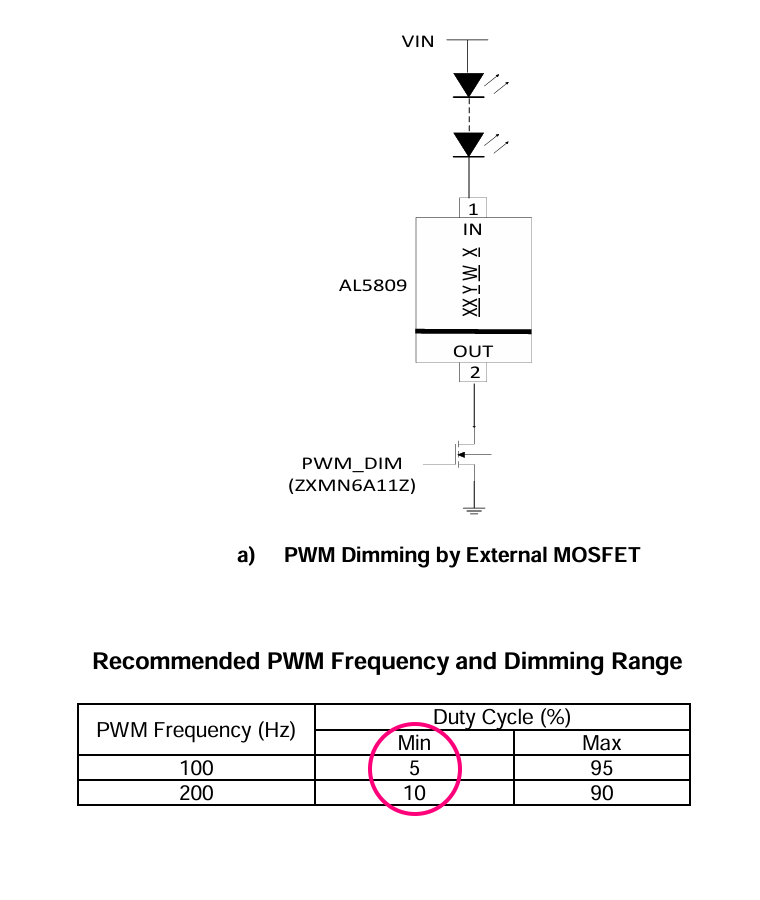
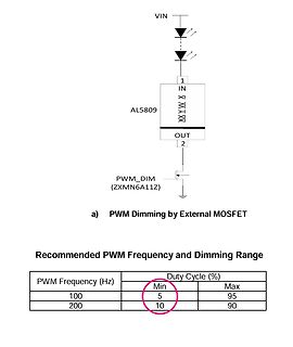
Schaltplan und Tabelle zur PWM-Dimmung
VIN AL5809 IN 1 X Y W X OUT 2 PWM_DIM (ZXMN6A11Z) a) PWM Dimming by External MOSFET Recommended PWM Frequency and Dimming Range PWM Frequency (Hz) Duty Cycle (%) Min Max 100 5 95 200 10 90
in „ATtiny85, energiesparende Schaltung mit PIR und LED FadeIn/FadeOut (Newbie)“ · Mikrocontroller und Digitale Elektronik · · Screenshots
-
 Bild
Bild
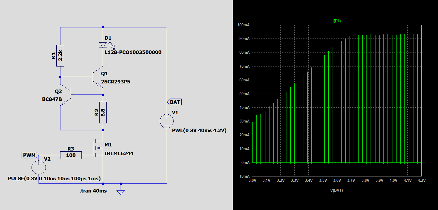
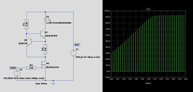
Schaltplan und Simulationsdiagramm einer LED-Schaltung
R1 2.2k D1 L128-PCO1003500000 Q1 2SCR293P5 Q2 BC847B R2 6.8 M1 IRLML6244 PWM V2 100 R3 BAT V1 PWL(0 3V 40ms 4.2V) .tran 40ms I(D1) 100mA 90mA 80mA 70mA 60mA 50mA 40mA 30mA 20mA 10mA 0mA -10mA V(BAT) 3.0V 3.1V 3.2V 3.3V 3.4V 3.5V 3.6V 3.7V 3.8V 3.9V 4.0V 4.1V 4.2V
in „ATtiny85, energiesparende Schaltung mit PIR und LED FadeIn/FadeOut (Newbie)“ · Mikrocontroller und Digitale Elektronik · · Screenshots
-
PDF
drv8312.pdf
Logic M3 Temp. Sense GND RESET_A Overload RESET_B sense OC_ADJ Protection RESET_C GVDD_C BST_C PVDD_C PWM Gate PWM_C Ctrl. Timing OUT_C Rcv. Drive GND_C GVDD_B BST_B PVDD_B PWM Gate PWM_B Rcv. Ctrl. Timing Drive OUT_B GND_B GVDD_A BST_A PVDD_A PWM Gate PWM_A Rcv. Ctrl. Timing Drive OUT_A GND_A 6 Submit
in „Versorgung von BLDC für Logic“ · Analoge Elektronik und Schaltungstechnik ·
-
Datei
dual_fading.c
my_delay(uint16_t milliseconds) { for(; milliseconds>0; milliseconds--) _delay_ms(1); } // 10-Bit PWM with 64 different settings void pwm_10_64_A(uint16_t delay){ int16_t tmp; #if STK500 TCCR1A = 0xC3; // inverted PWM on OC1A, 10 Bit Fast PWM #else TCCR1A = 0x83; // non-inverted PWM on OC1A, 10 Bit
in „PWM Led fading problem mit Soft-PWM Artikel“ · Mikrocontroller und Digitale Elektronik ·
-
Datei
10BIt.vhd
(Upwm0); pwm1 <= unsigned(Upwm1); else if(rising_edge(clk_in)) then if(pwm0 < to_unsigned(31,n_Bit))then-- pwm1 < to_unsigned(31,n_Bit))then pwm0<= (pwm0 + 1); --pwm1<= (pwm1 + 1); else pwm0 <= unsigned(Upwm0); --pwm1 <= unsigned(Upwm1); end if; -- pwm0&1 end if; -- rising_edge end if; -- reset end process count; output: Upwm0_out <= std_logic_vector(pwm0); Upwm1_out <= std_logic_vector(pwm1); end architecture counter_a
-
PDF
P2V_ESC_P1-2.pdf
Fig. 7 – P2V+ ON; motor full throttle PWM 37% duty cycle; no drive output PWM 47% duty cycle with motor drive PWM 72% duty cycle with motor drive 9765 9766 9767 Pulse width CH 1: PWM motor control input (at R1) CH 1: PWM motor control input (at R1) CH 1: PWM motor control input (at R1) CH 2: Motor drive “A” CH 2: Motor drive “A,” “B” and “C” CH 2: Motor drive “A,” “B” and “C” OK: 400Hz PWM signal at 37% duty OK: 400Hz PWM at 47% (about OK: 400Hz PWM signal
in „lächerliche Frage : was ist "kv" ?“ · Analoge Elektronik und Schaltungstechnik ·
-
PDF
515502_1__2_.pdf
IN DGND 27 DAC_PWM4 0.47 uF DAC4 3 3 EN_GATE [3] EXT_IB-FB [6] 76 GPIO-7 GPIO-06 26 4 4 PWM_CL 75 GPIO-5 GPIO-04 25 PWM_CH 25V 5 5 EXT_IA-FB EXT_IA-FB [6] VCC_3.3V PWM_BL 74 GPIO-3 GPIO-02 24 PWM_BH 10% U6A PWM_AL 73
in „Allgemeine Frage bezüglich Motor Treiber/Inverter“ · Analoge Elektronik und Schaltungstechnik ·
-
PDF
LV8907UW-D.PDF
Read / Write Read / Write 16h MRSPCT6 50% Input PWM Always OK Read / Write Read / Write 17h MRSPCT7 62.5% Input PWM Always OK Read / Write Read / Write 18h MRSPCT8 75% Input PWM Always OK Read / Write Read / Write 19h MRSPCT9 87.5% Input PWM Always OK
in „BLDC LV8907 via SPI einstellen funkt nicht..“ · Mikrocontroller und Digitale Elektronik ·
-
Datei
TXbuddy.asm
number of transmitted IR channels [2..8] .equ PPERBIT=18 ; base modulation frequency periods per bit ; ;PWM data .equ PWMPAUSE=2100 ; pause (microseconds) separating PWM frames .equ MAXPWMCHAN=4 ; max number of PWM permissible channels .equ ACTPWMCHAN=3 ; PWM channels scanned .equ FRAMECOUNTCENT=30 ; number
in „Anfängerfrage zu AVR Tiny12“ · Mikrocontroller und Digitale Elektronik ·
-
Datei
sauber.ino
SevSeg.h" // Für 7-Seg_Anzeige #include <IRremote.h> // Für Fernbedienung #include <Wire.h> // Für PWM comunikation // Register Adresse Lüfter #define Luefter1 0x04 #define Luefter2 0x02 // I²C Adresse PWM_IC #define pwm_ic 0x62 // Channel für Temperatur #define T1 A0 #define T2 A1 // Objekte IRrecv
in „Nummerneingabe SwitchCase AVR“ · Mikrocontroller und Digitale Elektronik ·
-
Datei
led_fade.asm
as a call subroutine elsewhere btfsc intcon,t0ie btfss intcon,t0if goto t0_done movlw -(1000000/256/PWM_STEPS-2) ; PWM_STEPS = 1 tick, 256 Tick = 1 sec addwf tmr0 movlw leds movwf fsr bsf TICK_FLAG movlw 256/PWM_STEPS addwf pwm skpc bcf TICK_FLAG movfw led movwf pwm_tmp movlw 8 movwf pwm_cnt pwm_loop rrf pwm_tmp skpnc clrf 0 comf 0,w addwf pwm btfsc TICK_FLAG incfsz 0 skip decfsz 0 incfsz 4 decfsz pwm_cnt goto pwm_loop rrf pwm_tmp,w movwf portb btfss TICK_FLAG goto t0_done-1 incfsz ticks skip incfsz ticks
in „LEDs an PIC ausglimmen lassen“ · Mikrocontroller und Digitale Elektronik ·
-
PDF
drv103.pdf
from Figure 5. For reference purposes, the equation for Voltage Controlled Duty Cycle calculating R PWM is included in Figure 5. Duty cycle can also be programmed by an analog voltage, V PWM . With V PWM ≈ 3.56V, duty cycle is about 90%. DUTY CYCLE RPWM (Nearest 1% Values) Decreasing this voltage results
in „Widerstände dimensionieren.“ · Analoge Elektronik und Schaltungstechnik ·
-
PDF
ILD6150.pdf
logic high level V PWM, high 2.6 – 5.5 V output stage enabled PWM voltage logic low level V PWM, low -0.3 – 0.5 V output stage disabled PWM output current ICC,PWM -23 -18 -12 µA VPWM = 0 V PWM delay time td, PWM, on – 0.8 – µs VPWM = rising to 2.5 V V = falling to switch 1 V t – 0.6 – µs V = falling to d, PWM, off PWM 0.5 V Vswitch rising to 1 V PWM signal frequency fPWM, ext – – 25 kHz 1) PWM pin has an internal pull-up circuit to high level if not connected externally on PCB 4.7 V CC,PWM PWM Figure 4 PWM
in „Kondensatorgröße für 5V LED-Treiber“ · Analoge Elektronik und Schaltungstechnik ·
-
Datei
main.c
interrupt.h> #include <iom16.h> #define BYTE unsigned char int main(void); //Globale Variablen BYTE pwm_count, ad_count, werte[3][2]; BYTE ad[3] = {MUX0, MUX1, MUX2}; //AD-Wandler BYTE pwm[3] = {0, (1<<PA3), (1<<PA4)}; //Ports für LED-MUX //PWM-Interrupt ISR(TIMER1_COMPB_vect) { cli(); if(pwm_count > 2) pwm_count=0; PORTA = pwm[pwm_count]; OCR1BL = werte[pwm_count][0]; OCR1BH = werte[pwm_count][1]; pwm_count++; sei(); } //AD-Interrupt ISR(ADC_vect) { cli(); if(ad_count == 0) ad_count = 3; werte[ad_count
in „AVR RGB-LED PWM MUX“ · Mikrocontroller und Digitale Elektronik ·
-
Datei
MSP3400_ATMEGA32_ADC_2.ino
< targetADC - 8) { if (pwm1Value < 255 - pwmStep) pwm1Value += pwmStep; } else if (adc2 > targetADC + 8) { if (pwm1Value > pwmStep) pwm1Value -= pwmStep; } OCR0 = pwm1Value; // PD7 (Timer2) regelt ADC3 int adc3 = analogRead(A3); if (adc3 < targetADC - 8) { if (pwm2Value < 255 - pwmStep) pwm2Value += pwmStep; } else if (adc3 > targetADC + 8) { if (pwm2Value > pwmStep) pwm2Value -= pwmStep; } OCR2 = pwm2Value; } // ----------------------------------------------
in „Zeigt her eure Kunstwerke (ab 2023)“ · Projekte & Code ·
-
Datei
MSP3400_ATMEGA32_ADC_2.ino
< targetADC - 8) { if (pwm1Value < 255 - pwmStep) pwm1Value += pwmStep; } else if (adc2 > targetADC + 8) { if (pwm1Value > pwmStep) pwm1Value -= pwmStep; } OCR0 = pwm1Value; // PD7 (Timer2) regelt ADC3 int adc3 = analogRead(A3); if (adc3 < targetADC - 8) { if (pwm2Value < 255 - pwmStep) pwm2Value += pwmStep; } else if (adc3 > targetADC + 8) { if (pwm2Value > pwmStep) pwm2Value -= pwmStep; } OCR2 = pwm2Value; } // ----------------------------------------------
in „AUDIOCONTROLLER MSP3400C einfach mit ATMEGA32 ansteuern“ · Projekte & Code ·
-
Datei
linux-2.6.27.grasshopper.1.patch
"icnova_pwm" +#define PWM_ERR(pwmnr, msg, arg...) \ + printk(KERN_CRIT PWM_NAME "PWM%d: " msg, pwmnr, arg) + +#define icnova_pwm_get_global_mode(ch) __raw_readl(ch.regs & ~0x03FF) +#define icnova_pwm_set_global_mode
in „AVR32 grasshopper patch für ATMEL buildroot 2.2.1“ · Mikrocontroller und Digitale Elektronik ·
-
 Bild
Bild
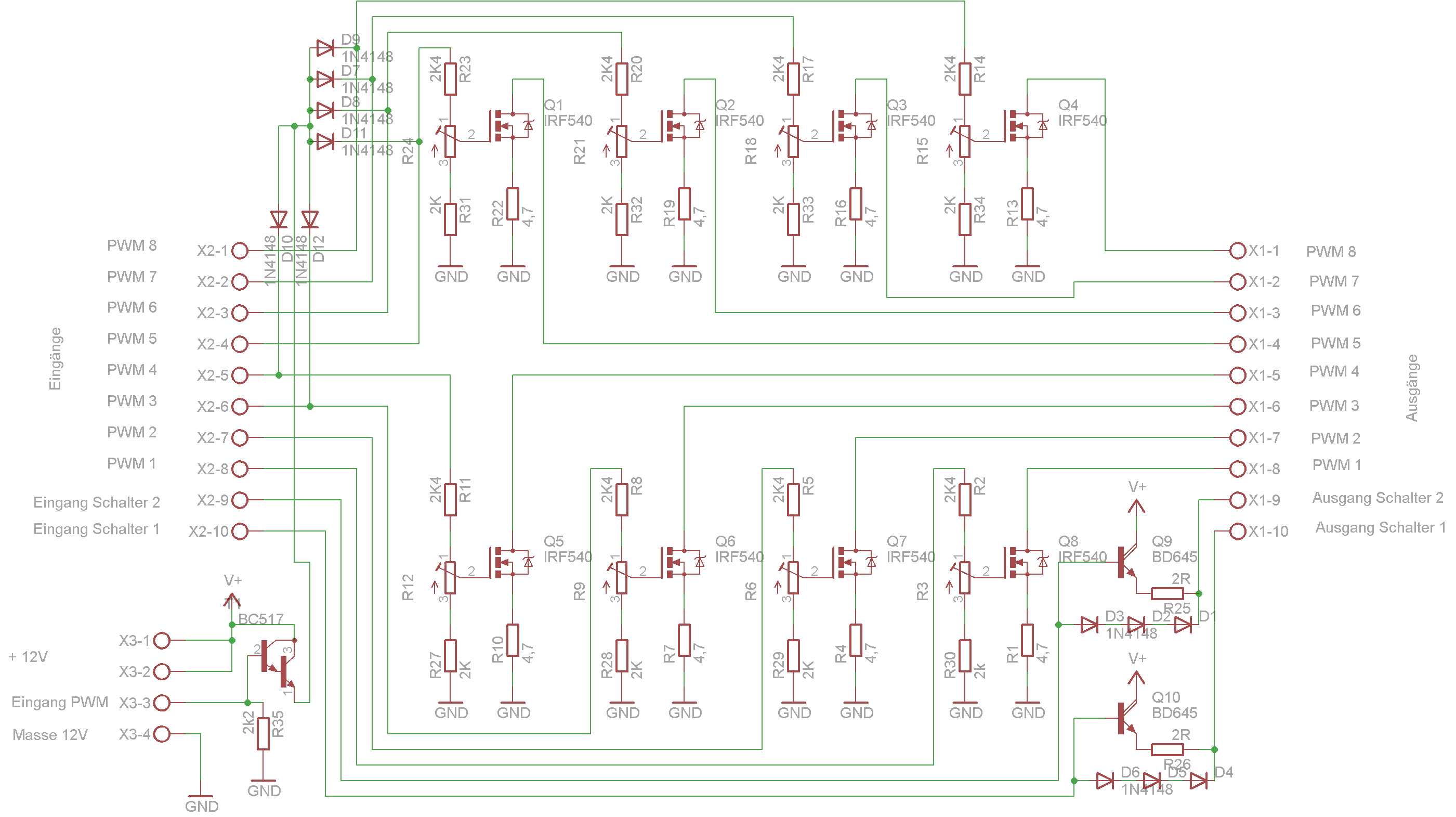
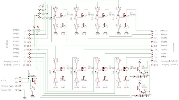
Schaltplan einer MOSFET-Leistungstreiberstufe
PWM 8, X2-1, D9, 1N4148, D1, D8, D11, 1N4148, X2-2, PWM 7, X2-3, PWM 6, X2-4, PWM 5, X2-5, PWM 4, X2-6, X1-5, PWM 4, X2-7, PWM 2, X2-8, PWM 1, X1-6, PWM 3, X1-7, PWM 2, X1-2, PWM 6, X1-4, PWM 5, X1-1, PWM
in „Suche geeigntes Netzteil für 3x LED-Downlights Konstanstrom 250mA“ · Haus & Smart Home · · Schaltpläne
-
PDF
TMC4671-LA_datasheet.pdf
polarity of the logic level low side gate control signal. Figure 36: PWM Gate Driver Control Polarities PWM_POLARITIES[1...0] PWM_HIGH_SIDE PWM_LOW_SIDE 0 0 PWM_H PWM_L 0 1 PWM_H not PWM_L 1 0 not PWM_H PWM_L 1 1 not PWM_H not PWM_L Table 24: Status Flags Register ©2022
-
Datei
tiny1b.ino
; volatile uint16_t seccount = 0; volatile uint16_t lastsec = 0; uint8_t daycount = 0; static void pwm_init(void) { DDRB |= _BV(PB0); // set PWM pin as OUTPUT TCCR0A |= _BV(WGM01) | _BV(WGM00); // set timer mode to FAST PWM TCCR0A |= _BV(COM0A1); // connect PWM signal to pin (AC0A => PB0) } /* When timer
in „AtTiny13: Watchdog Interrupt dauert lange“ · Mikrocontroller und Digitale Elektronik ·
-
Datei
auschaltverz_gerung.c
Overflow interup enable OCR0 = 255; //Initalwert setzen (PWM ist aus) } void runterdimmen(void) { while(enable == 0x01) { OCR0 = max; if(max >= 253) // auch hier beachten, PWM ist invertiert! { OCR0 = 255; enable = 0x00; max = 0; } } PORTC = 0x00; // Problem:
in „ATMEGA16 Timer“ · Mikrocontroller und Digitale Elektronik ·
-
Datei
pinout.h
dht_pin 11 //led #define LED1_port C #define LED1_pin 13 //#define LED2_port C #define LED2_pin 13 //pwm //#define PWM_port D //#define PWM_pin 4 //ADC //#define adc_port C #define adc_pin 2 //sd-Schacht 1 #define sd_cs_port B #define sd_cs_pin 6 #define sdSpiNr 1 //net-Schacht 2 #define enc_cs_port B
in „Header Datei für Konfiguration erstellen“ · Mikrocontroller und Digitale Elektronik ·
-
Datei
FET140_demolist_c.txt
/li> <li>fet140_ta15.c - Timer_A Toggle P1.1 With TA0 up-downmode, HF XTAL ACLK</li> <li>fet140_ta_pwm01.c - Timer_A PWM TA1-2 upmode, DCO SMCLK</li> <li>fet140_ta_pwm02.c - Timer_A PWM TA1-2 upmode, 32kHz ACLK</li> <li>fet140_ta_pwm03.c - Timer_A PWM TA1-2 upmode, HF XTAL ACLK</li> <li>fet140_ta_pwm04
in „MSP430 SPI-Datenübertragung temperaturabhängig?“ · Mikrocontroller und Digitale Elektronik ·
-
Datei
saw_tooth_1.vhd
--********************************************************************************************* -- PWM_MAX : PWM_MAX value of the Sawtooth-fct -- steps = T_saw/T_FPGA -- inc/step = PWM_MAX/steps -- k = inc/step * 128 = PWM_MAX*T_FPGA*128 / T_saw -- k = PWM_MAX * f_saw * 128 / f_FPGA --***************
in „totzeit von 1µs bauen“ · Analoge Elektronik und Schaltungstechnik ·
-
Datei
saw_tooth_1.vhd
--********************************************************************************************* -- PWM_MAX : PWM_MAX value of the Sawtooth-fct -- steps = T_saw/T_FPGA -- inc/step = PWM_MAX/steps -- k = inc/step * 128 = PWM_MAX*T_FPGA*128 / T_saw -- k = PWM_MAX * f_saw * 128 / f_FPGA --***************
-
PDF
rnvn2dualmotor.pdf
Motor 1 Motor2_in1 = 1 'Drehrichtung Motor 2 Motor2_in2 = 0 'Drehrichtung Motor 2 For I = 0 To 511 Pwm1a = I Pwm1b = I Waitms 25 Next I Wait 120 'Bremsen Pwm1a = 0 Pwm1b = 0 Wait 2 Motor1_in1 = 0 'Drehrichtung Motor 1 Motor1_in2 = 0 'Drehrichtung Motor 1 Motor2_in1 = 0 'Drehrichtung Motor 2 Motor2_in2
in „Ansteuerung von Motor-Treiber mit PWM“ · Mikrocontroller und Digitale Elektronik ·
-
PDF
NCP81151B-D-931445.pdf
Forward Voltage VCC = 5 V, forward bias current = 2 mA 0.1 0.4 0.6 V PWM INPUT PWM Input High 3.4 V PWM Mid−State 1.3 2.7 V PWM Input Low 0.7 V ZCD Blanking Timer 350 ns HIGH SIDE DRIVER Output Impedance, Sourcing Current V −V = 5 V 0.9 1.7 W BST SW Output Impedance, Sinking
in „Push-Pull-Ausgang der alles kann :)“ · Mikrocontroller und Digitale Elektronik ·
-
PDF
CH572DS1_en.PDF
_PWM2_DATA 0x40005006 PWM2 data hold register (16-bit width) 0xXXXX R8_PWM3_DATA 0x40005006 PWM3 data hold register (8-bit width) 0xXX R16_PWM3_DATA 0x40005008 PWM data hold register 2 0xXXXX R32_PWM4_5_DATA 0x40005010 PWM data hold register 3 0xXXXXXXXX R16_PWM4_DATA 0x40005010 PWM4 data hold register (16-bit width) 0xXXXX R8_PWM4_DATA 0x40005010 PWM4 data hold register (8-bit width) 0xXX R8_PWM5_DATA 0x40005011 PWM5
in „Eagle 7.5 Bibliothek - bitte um Prüfung und Hinweise“ · Platinen ·
-
Datei
main.c
void pulse_onRight(void); void hs_onLeft(void); void hs_onRight(void); void hs_onStart(void); void pwm_onUp(void); void pwm_onDown(void); void pwm_onLeft(void); void pwm_onRight(void); void pwm_onStart(void); void pwmHs_onUp(void); void pwmHs_onDown(void); void pwmHs_onLeft(void); void pwmHs_onRight(
in „PWM-Ausgabe stimmt nicht bei AVR DDS“ · Mikrocontroller und Digitale Elektronik ·