replace a single (OUTPUT) device and its external resistor bias network. The Bias Resistor PIN 1 R1 BASE Transistor (BRT) contains a single transistor with a monolithic bias (INPUT) network consisting of two resistors; a series base resistor and a base− R2 emitter resistor. The BRT eliminates these individual
eigentlich die Kollektoren von Q7 und Q8 nicht direkt miteinander verbinden und dann noch mit den Basen verbinden? Das würde das Layout vereinfachen. Es wird doch nur der Spannungsfall der BE-Strecke benötigt, so als ob dort 2 Dioden eingesetzt wären.
eigentlich die Kollektoren von Q7 und Q8 nicht direkt >miteinander verbinden und dann noch mit den Basen verbinden? Das würde >das Layout vereinfachen. Google mal nach "Diamond Buffer" oder schau dir das DB vom BUF634 an.
Capacitance range CR 0.1 µF to 330 µF Tolerance on R ± 10 % ± 20 % Nominal voltage UR U R 85°C 6.3 10.0 16 20 25 35 125°C 4.0 6.3 10 13 16 23 Surge voltage V- U R 85°C 8.0 13.0 20 26 33 46 125°C 5.0 9.0 12 16 21 28 Reverse voltage max. 25°C (1 V - 0.10 U ) / 125°C (0.1 V - 0.01 U ) R R 85°C (0.5 V - 0.0R
schrieb im Beitrag #7442522: > AM statt FM Ich wohne hier nicht weit von Ramstein entfernt. Die Air Base Ramstein ist ein Dreh- und Angelpunkt der Amerikaner, nichtnur für Europa, sondern von hier werden alle Drohnen im Ostbereich gesteuert. Ich kann sehr gut deren Flugfunk mithören, ausschließlich
verschiedenste transistorisierte und mit Analog ICs wie TBA120S, TCA990 u.ä. meine UKW Funkgeräte. 2N3866, BFW16, BFX89 fanden alle in meine Geräte hinein. Die UKW Berichte waren eine große Hilfe zum Lernen durch Lesen von Berichten wie es funktionieren soll. Es war ein Glück für mich, daß ich meine Lehre bei einer
PCMCIA cards. The thermal resistance and power dissipation are the best available. Standard Pack Base Part Number Package Type Orderable Part Number Form Quantity IRLML2502TRPbF Micro3™ (SOT-23) Tape and Reel 3000 IRLML2502TRPbF Absolute Maximum Ratings Parameter Max. Units VDS Drain- Source Voltage
approach is preferred. In most cases, a Colpitts oscillator is successfully used. Circuits with grounded base exhibit severe stability problems and even the Colpitts oscillator, based on its emitter circuitry, shows ocassional unwanted resonances up to 6GHz. This is due to the fact that the modern Si and SiGe
velvet-chess/blob/master/fathomrs/build.rs#L33 Wenn du LLVM installierst, sollte es funktionieren. LLVM-16.0.0-win64.exe https://github.com/llvm/llvm-project/releases/tag/llvmorg-16.0.0
256-bit - Enable generation of 256-bit load/stores even if we prefer 128-bit. amx-bf16 - Support AMX-BF16 instructions. amx-fp16 - Support AMX amx-fp16 instructions. amx-int8 - Support AMX-INT8 instructions.
muss, dann ein Compute Module 4 zusammen mit so einem Trägerboard: https://www.berrybase.de/mini-base-board-a-fuer-raspberry-pi-compute-module-4 Da kannst Du dann entweder ein CM4 mit Onboard EMMC nehmen (die sind wesentlich zuverlässiger), und/oder Du packst eine M.2 Typ M 2242 NVME SSDs in den
Filesystems. Ein auch nicht mehr so ganz frischer RasPi eines 24x7 Kiosk-Displays, Typ SanDisk Ultra SC16G: [code] Last write time: Wed Sep 19 14:40:49 2018 Mount count: 37 Lifetime writes: 90 GB [/code]
Achims Stecker sind Amphenol C091 https://www.amphenol-industrial.de/en/C091-M16-Circular-Connectors aber die gibt es maximal 14-polig, keine 16. Bei Mouser kann man nach 16-poligen Rundsteckern suchen, aber schon "Standard-Typen" findet 1075 verschiedene: https://www.mouser.de
Document No. JGC42-8869B P. 1/16 製品仕様書 Specification of Piezoelectric Ceramic Resonator 決定年月日 Issue Date : April 23, 2019 1. 品番 Part Number 当 社 品 番 Murata Part Number テーピング品 CSTNE16M0VH3L000R0 Taping バラ品 Bulk CSTNE16M0VH3L000B0 2. 適
Beschränkungen. Selbst Bastler bauen heute 4 lagig! Ja und? Das kann auch Eagle, prinzipiell bis 16 Lagen. Wobei das dann WIRKLICH sportlich wird ;-) Kennt jemand ein größeres, komplexeres Layout mit Eagle und mehr als 6 Lagen? Das wär mal ein netter Wettbewerb.
. Nur das Kicad eben deutlich mehr kann und garnichts kostet. Klar kann man mit Eagle PCBs mit 16 Lagen machen. Ist eben nur eine Schweinearbeit verglichen damit ein Tool zu nutzen das einige dieser Luxus, Stützräder, Rollator Funktionen hat, die einem das Leben einfacher machen. Und auch wenn
and 50Ω through terminator to input channel II. Check that DC input coupling is selected. Set time base to 1ms/div. Adjust R658 (15) for 5 division signal height. (16) R422: FET operating point CH II. Locate and identify R422 (16) in CH II section of the YPA-Board. Press CHI/II pushbutton (in!) for channel
the backup domain when enabled. (+) De-Initializes common part of the HAL. (+) Configure The time base source to have 1ms time base with a dedicated Tick interrupt priority. (++) SysTick timer is used by default as source of time base, but user can eventually implement his proper time base source (a
Also ein Puls hat eine Periodendauer von angenommen 10µs. Das sind 100khz. Wäre noch machbar mit 16Bit Timer und 16MHz "Arduino". Auflösung wäre 160, sollte für etwas Phasenverschiebung reichen. Jetzt gehst du ran und konfigurierst dir deinen Timer für 100kHz. Wie gesagt am Ende programmierst du
muss doch wissen wieviele Pulse er in einer Umdrehung machen kann. Um zu sagen, wenn ich jetzt bspw 16,3U/min mache wieviel Impulse er absetzten muss in welchen Zeitschritten
Absolute Maximum Rating System (IEC 134). SYMBOL PARAMETER CONDITIONS MIN. MAX. UNIT V collector-base voltage open emitter − 50 V CBO VCEO collector-emitter voltage open base − 45 V VEBO emitter-base voltage open collector − 5 V C collector current (DC) − 500 mA CM peak collector current − 1 A I peak
ensuring a smoother user experience. • Streamlined Packages: We have optimized our package base, making it nearly identical across different underlying package bases and desktop choices. This standardization improves predictability and enhances security. • Consistent Application Packages: Regardless of the chosen package base or desktop environment, the application packages remain the same. This ensures consistent functionality and ease of use. • Improved Ubuntu-Based Assemblies: We have successfully removed the unnecessary
============================= [/code] Benutzername schleichkatze Angemeldet seit 07.08.2023 16:55 Beiträge 0
oder irgendetwas, was Transienten abblocken soll, eingezeichnet. https://kb.shelly.cloud/knowledge-base/shelly-plus-1pm#ShellyPlus1PM(SNSW-001P16EU)-Basicwiringdiagram Das Thema ist doch durch. Für "echtes" Lastrelais ist das Ding doch viel zu klein. Ich hüte mich, sowas anzuschließen, was den Kurzschlussstrom
0x0020 8 / 16b 8 / 16b I / O 8b 0x0060 8b Ext I / O 0x0100 2Kx8 8b LG 8 SRAM M 2Kx8 LD / ST SRAM 0x0900 In te 0x2100 rfa CSRIR ce 1Kx16 16b 16b D D A H SD X Y L uDSC SRAM 0x2900 As shown above, the LGT8XM core can
Victoria J. schrieb im Beitrag #7422080: > Am elegantesten finde ich aber die Variante 10BASE-T1L PoDL und die > Daten direkt ins Netzwerk einbinden zu können. 10BASE-T1L ist eine Punkt-zu-Punkt-Verbindung. Dafür brauchst Du eine Sterntopologie und einen Switch im Sternpunkt. 10BASE-T1S
werden müssen pro Gerät 24 16-bit Werte mit einer Aktualisierungsrate von mindestens 5 Hz. Macht bei fünf Geräten 1200 Bytes pro Sekunde ohne Protokolloverhead.
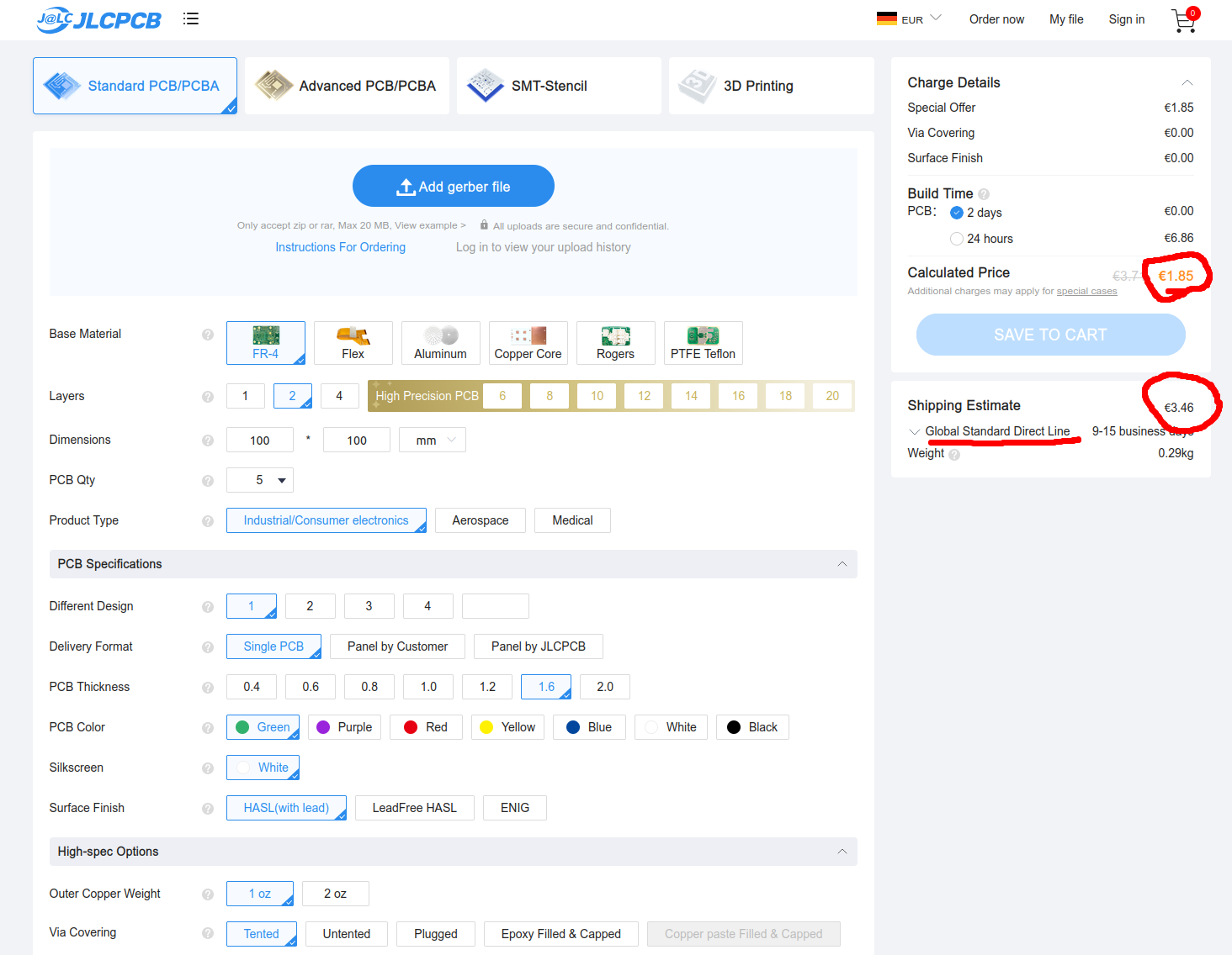
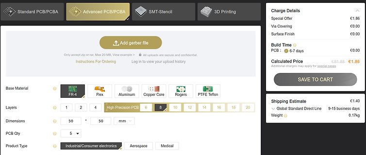
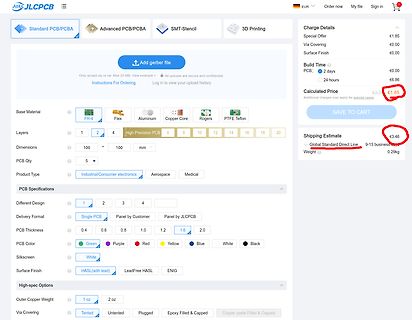
€1.85 SAVE TO CART Shipping Estimate Global Standard Direct Line 9-15 business days Weight 0.29kg Base Material FR-4 Flex Aluminum Copper Core Rogers PTFE Teflon Layers 1 2 4 6 8 10 12 16 20 Dimensions 100 mm PCB Qty 5 PCB Specifications Different Design Delivery Format PCB Thickness PCB Color Silkscreen
time-out flag after: 1s Time base/WDT clock output:8Hz F8 1 0 0 101X-X011-X C The WDT time-out flag after: 1/2s Time base/WDT clock output:16Hz F16 1 0 0 101X-X100-X C The WDT time-out flag after: 1/4s Time base/WDT clock output:32Hz F32 1 0 0 101X-X101-X C The WDT time-out flag after: 1/8s Time base/WDT clock output:64Hz F64 1 0 0 101X-X110-X C The WDT time-out flag after: 1/16s F128 1 0 0 101X-X111-X C Time base/WDT clock output:128Hz Yes The WDT time-out flag after: 1/32s TEST 1 0 0 1110-0000
C5250301101055084D4D4D4D4D4D4D4D java.security.InvalidAlgorithmParameterException: Wrong IV length: must be 16 bytes long at java.base/com.sun.crypto.provider.CipherCore.init(CipherCore.java:525) ``` Der IV ist richtig. Sonst würde miller-alex.de/WMbus ja meckern. Lasse ich beim IV die letzte Hälfte
Du das letzte 0xFF? Die verschlüsselte Nachricht kann nur ein vielfaches der AES Blocklänge sein (16 Byte), daraus ergibt sich dass 0xFF nicht zur verschlüsselten Nachricht gehört.
= 2.7 V 7 IN −40°C ≤ TJ≤ 125°C 5.4 R L 43 Ω(3) VIN= 3.3 V 10 X Option −40°C ≤ TJ≤ 125°C 8 VIN= 5 V 16 VIN= 2.7 V 7.5 −40°C ≤ TJ≤ 6 125°C R = 43 Ω L (3) VIN= 3.3 V 11 Y Option −40°C ≤ TJ≤ 8.75 125°C VIN= 5 V 15 VOUT (MIN) Minimum Output Voltage Under Load V VIN= 2.7 V 5 −40°C ≤ TJ≤ 3.75 125°C R L 15 Ω
only in the Extended Comprehensive SMART error log. The Summary SMART error log may be wraps after 2^16 hours, or 2730 days and 16 hours, or about 7.5 years.] If any errors were detected, the Logical Block Address (LBA) of the first error is printed in decimal notation. single byte. The Logical Block Address
to override this guess. Note that the printed output of smartctl displays most numerical values in base 10 (decimal), but some values are displayed in base 16 (hexadeci- mal). To distinguish them, the base 16 values are always displayed with a leading "0x", for example: "0xff". This man page follows the
Product Name 8 Port 1000M PoE+ Switch Ethernet Port 8 * 10/100/1000Mbps PoE Port Switching Capacity 16Gbps Throughput 11.9Mpps Packet Buffer 1Mb MAC Address 2K Jumbo Frame 2048bytes Transfer Mode Store and forward Mean Time Between Failure 100000 hour Network protocol IEEE802.3 (10Base-T) IEEE802.3u (100Base-TX) IEEE802.3ab (1000Base-TX) IEEE802.3z(1000Base-FX) IEEE802.3x (Flow control) PoE Protocol IEEE802.3af (15.4W) IEEE802.3at (30W) POE Pin 1/2 +, 3/6 - PoE Power Budget 120W Industry Standard
of pulses */ /* frequencies */ uint32_t LC_Freq; /* measured frequency (in Hz) */ uint32_t f_i; /* base frequency (in Hz) */ uint32_t f_x; /* frequency with C_x/L_x (in Hz) */ uint16_t f_n = 140; /*(in Hz) offsets the zero measurement of the inductance. Example - "At 300 the initial value of the inductance
C/W Maximum Junction-to-Ambient Steady-State 59 75 °C/W Maximum Junction-to-Lead Steady-State RθJL 16 24 °C/W www.umw-ic.com 1 UTD Semiconductor Co.,Limited R U M W AO4459 P-Channel MOSFET Electrical Characteristics (TJ=25°C unless otherwise noted) Symbol Parameter Conditions Min Typ Max Units BV DSS
Alarm and Sleep Outputs logical High Level VOH = Vss - 2V 500 I'A Logical Low Level VOL = VOD 1 I'A 10·16 -XChangeVe -XChangeVie D wr DF wer P W! P W! yNO yNO b bu kto functional description kt w Clc w Ci ww om ww om .docu rack. .docu rack. - -t A block diagram of the MM5316 digital alarm Output Common Source
Type values Type List Sequence of Uint16 LanguageBaseAttributeIDList Language used M Data See [2] See [2] for the Stings in Element the Record Sequence Service Availability Load Factor O Uint8 As defined in SDP Dynamic section of [1] BluetoothProfileDescriptorLis
state */ uint8_t Index; /* prescaler table index */ uint8_t Bits; /* prescaler register bits */ uint16_t GateTime; /* gate time in ms */ uint16_t Top; /* top value for timer */ uint32_t Value; /* temporary value */ /* control flags */ #define RUN_FLAG 1 /* run flag */ #define WAIT_FLAG 2 /* enter/run
selbe Aderpaar? (Wieso) Gibt es keine Kollisionen? Beispielsweise bei Single Pair Ethernet (SPE) 10BASE-T1L: https://www.analog.com/en/technical-articles/enabling-seamless-ethernet-to-field-with-10base-t1l-connectivity.html > 10BASE-T1L core capability is a full duplex, dc balanced, > point-to-point
Danke für die Antworten. Der Signalverarbeitungsaufwand erklärt dann wohl auch, weshalb 10BASE-T1L vollduplex (point-to-point) ist aber 10BASE-T1S nur halbduplex ist (multidrop).
-02T16:13:54 INFO common.c: Attempting to write 207652 (0x32b24) bytes to stm32 address: 134217728 (0x8000000) 2023-05-02T16:13:55 INFO common.c: Flash page at addr: 0x08000000 erased 2023-05-02T16:13:56
: 0x00a937bc 2023-05-02T16:35:48 INFO common.c: Attempting to write 207652 (0x32b24) bytes to stm32 address: 134217728 (0x8000000) 2023-05-02T16:35:49 INFO common.c: Flash page at addr: 0x08000000 erased 2023-05-02T16:35:50
/* Print.h - Base class that provides print() and println() Copyright (c) 2008 David A. Mellis. All right reserved. This library is free software; you can redistribute it and/or modify it under the terms of the GNU Lesser

 Bild
Bild
 Bild
Bild
 Bild
Bild
 Bild
Bild