-
 Bild
Bild
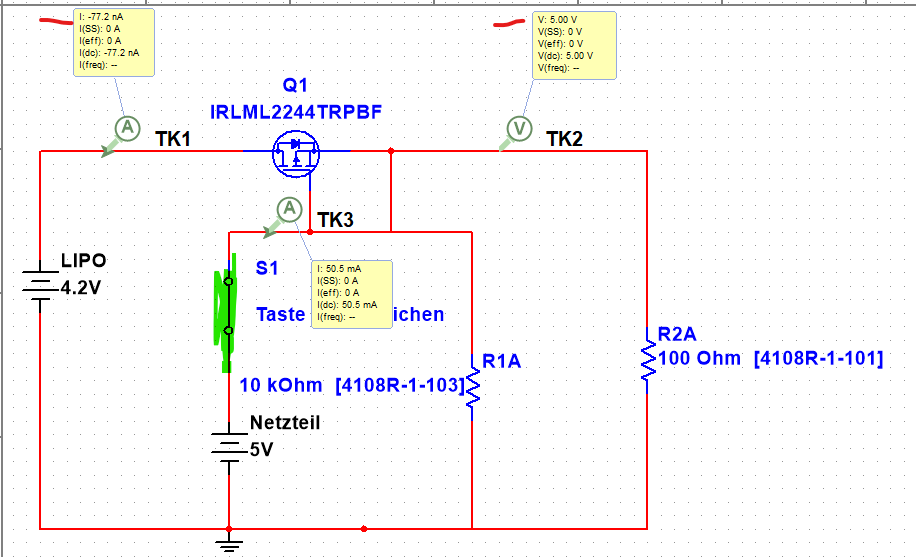
Schaltplan mit MOSFET und Messpunkten
I: -77.2 nA I(SS): 0 A I(eff): 0 A I(dc): -77.2 nA I(freq): -- Q1 IRLML2244TRPBF V: 5.00 V V(SS): 0 V V(eff): 0 V V(dc): 5.00 V V(freq): -- TK1 TK2 TK3 LIPO 4.2V S1 Taste ichen 10 kOhm [4108R-1-103] R1A Netzteil 5V R2A 100 Ohm [4108R-1-101]
-
Thread
SAS-Festplatten.
(prx) A. K. schrieb im Beitrag #7705263: > Disks aus Storage-Systemen der gehobenen Klasse sind oft mit sowas wie > 524 statt 512 Byte Sektoren formatiert. Ohne Lowlevel-Formatierung geht > dann nichts
12.5mm (also etwa .05"). https://preisvergleich.heise.de/seagate-barracuda-compute-5tb-st5000lm000-a1521940.html Die ersten 1-TB-2.5"-Platten waren 12.5mm dick. Das war vor 2010. Gibts erstaunlicherweise immer noch: https://preisvergleich.heise.de/toshiba-mk1059gsm-1tb-a518790.html Mittlerweile
-
Thread
Funkrelais durch Pi ansteuerbar
Kommandos für On und Off, um das Relais zu schalten. Sehr verbreitet sind dort Systeme mit dem PT2262 o.ä.
nicht getestet: https://www.ebay.de/itm/314119906408?chn=ps&_ul=DE&_trkparms=ispr%3D1&amdata=enc%3A1zaV7m6hMQFiG0zGmwaWRCg14&norover=1&mkevt=1&mkrid=707-134425-41852-0&mkcid=2&mkscid=101&itemid=314119906408&targetid=1716911581679&device=c&mktype=pla&googleloc=9042740&poi=&campaignid=21360358514&mkgroupid
-
Thread
iso.Stick zur Installation eines Linux vorbereiten
Einheiten: Sektoren von 1 * 512 = 512 Bytes Sektorgröße (logisch/physikalisch): 512 Bytes / 512 Bytes E/A-Größe (minimal/optimal): 512 Bytes / 512 Bytes Festplattenbezeichnungstyp: gpt Festplattenbezeichner: B6F6D482-E72A-8342-BFCF-A313E837CCBF Gerät Anfang Ende Sektoren Größe Typ
A. B. schrieb im Beitrag #7704444: > Linux-Mint: USB inmage writer - Mintstick - Systemprogramm Alternativ: "Balena Etcher". Das läuft unter Windows, macOS und auch Linux (sofern das 'ne graphische
-
 Bild
Bild
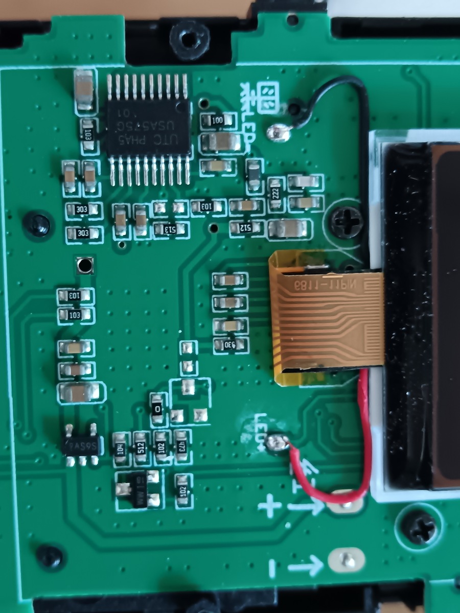
Nahaufnahme einer bestückten Leiterplatte
UTC PHA5 5G, 101, 103, 102, 222, 512, 513, 330, 01, LED, S65V4, 104, 102, 102, 101, 103, 103, 30E, 30E, 118a, + , -
-
 Bild
Bild
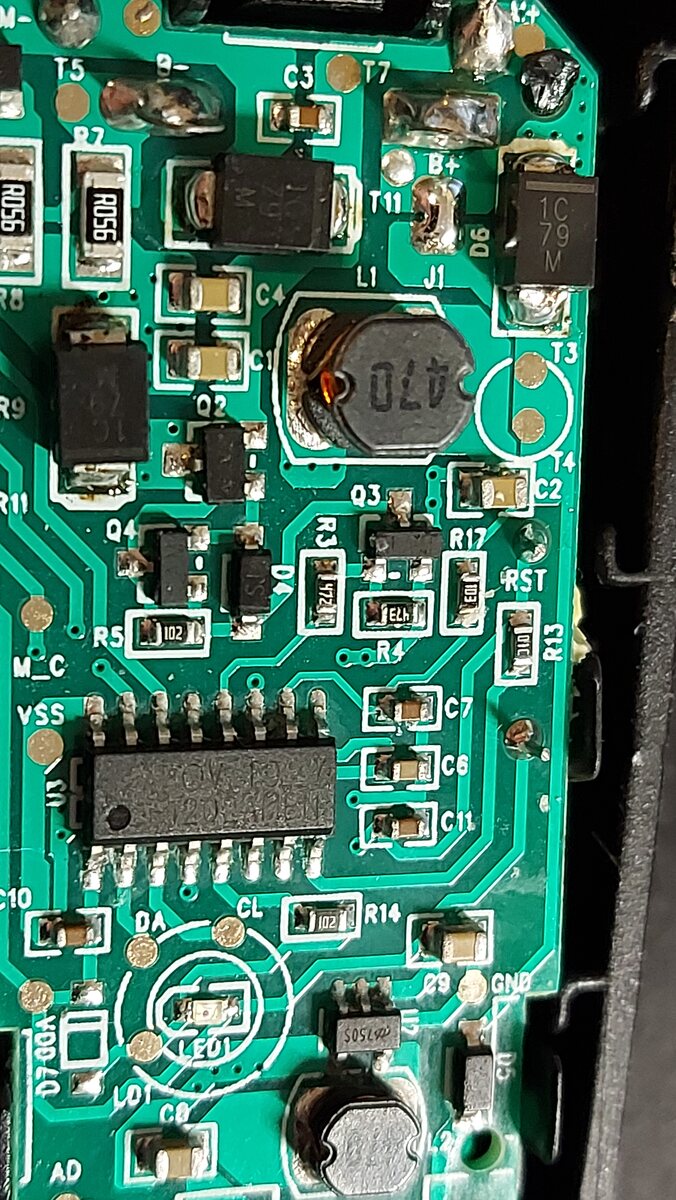
Nahaufnahme einer bestückten Leiterplatte
T5, C3, T7, R7, B+, D6, 1C 79 M, R056, A056, T11, C4, L1, J1, R8, T3, C1, Q2, 470, R9, Q3, T4, C2, R11, Q4, R3, R17, RST, R5, 102, D, 172, E, 47, R13, 101, R4, M_C, C7, C6, VSS, C11, 101, R13, C10, CL, R14, DA, 102, GND, D00V, LED1, S05292,
-
Thread
"Class A/B" versus "Class D" Verstärker für HiFi-Anlagen
wie "N HDMI-2.1 Eingänge" oder "kann Dolby Atmos dekodieren" o.ä., insgesamt sind die NAD-Modelle mit Class-D auch erheblich teurer als die A/B Mittelklassemodelle anderer Hersteller.
prominent "Class A" auf die Frontblende schreiben, obwohl es dann nichtmal Klasse A sind. Wie dem auch sei: Je Bumms, desto Wumms.
-
Thread
Pigment-Tinte Lösungsmittel
https://www.ebay.de/itm/395135532267?chn=ps&_ul=DE&var=663715739929&_trkparms=ispr%3D1&amdata=enc%3A1dx6nIvaRSoq0JY1O3xsNvg35&norover=1&mkevt=1&mkrid=707-134425-41852-0&mkcid=2&mkscid=101&itemid=663715739929_395135532267&targetid=1716911581119&device=c&mktype=pla&googleloc=9043641&poi=&campaignid=17943303986&
-
Thread
Was könnte an diesem Verstärker kaputt sein? (Denon AVR-3801)
Genau, viel zu ueberkompliziert. Ich benutze meinen Yamaha RX-V3000 in 2.0 mit zwei dicken Boxen von T&A. Das muss reichen. Vanye
auch schief gehen. Dankenswerterweise hat Denon jede Menge "Test Points" vorgesehen, wie z.B. TP101 im anhängenden Bild meiner "DSP/Audio Unit" Platine.
-
Thread
Smartphone SIM Identitaetsdiebstahl
"The rules were scheduled to take effect on July 8, but the FCC on July 5 granted phone companies a waiver that delays implementation until the White House Office of Management conducts a further review."
Erdstrahlen, Mana und Steinsalzenergien. Weiß doch jeder, das ist irrer Verschwörungstheoretiker 101 sozusagen.
-
Thread
Hilfestellung zu Spannungsteiler+Potentiometer
Welchen Wert hat das Poti? https://www.reichelt.de/de/de/spannungsregler-fest-4-8--5-2-v-to-220--a-7805-p23443.html
nur einen her. Aber egal. > Im Datenblatt > steht: "Minimum load current for regulation is 5 mA." Hat jemand > Erfahrung damit? Es wird höchste Zeit dass du dir mal anschaust wie groß deine Last auf der 5V Seite ist. Daraus ergibt sich a) Welchen Strom die Spannungsregler liefern müssen
-
 Bild
Bild
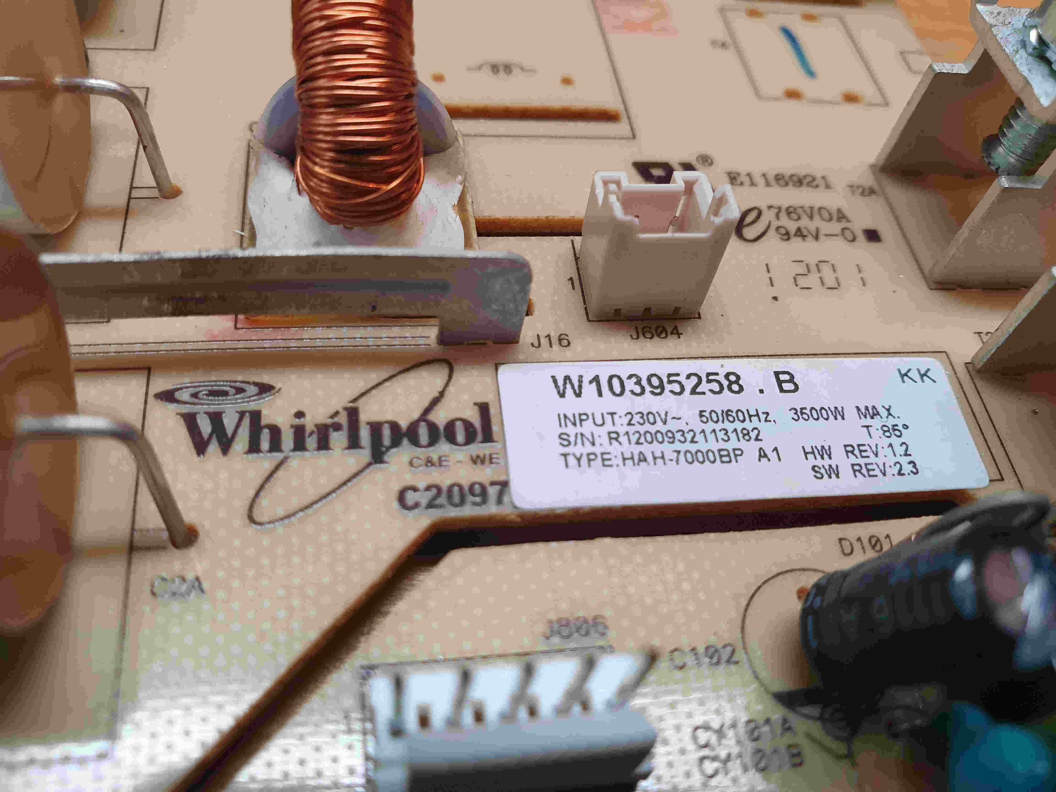
Nahaufnahme einer Whirlpool-Leiterplatte mit Bauteilen
E116921 12A 76V0A 1201 KK W10395258.B INPUT: 230V~, 50/60Hz, 3500W MAX. T: 85° S/N: R1200932113182 TYPE: HAH-7000BP A1 SW REV: 2.3 Whirlpool C&E - WE C2097 J16 J604 D101 CY181A CY181B
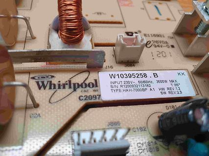
-
Thread
Netzwerkänderung?
der Umstellung zu überdenken? Nicht nur, aber besonders bei Boxen/IoT-Geräten ohne Konsole ist es i.A. eleganter, DHCP zu nutzen, und im DHCP-Server die MAC fest auf eine IP zu binden.
, ohne DHCP im Netz. > Nicht > nur, aber besonders bei Boxen/IoT-Geräten ohne Konsole ist es i.A. > eleganter, DHCP zu nutzen, und im DHCP-Server die MAC fest auf eine IP > zu binden. Da kann es Sinn machen, aber man ist dann halt vom DHCP-Server abhängig.
-
Thread
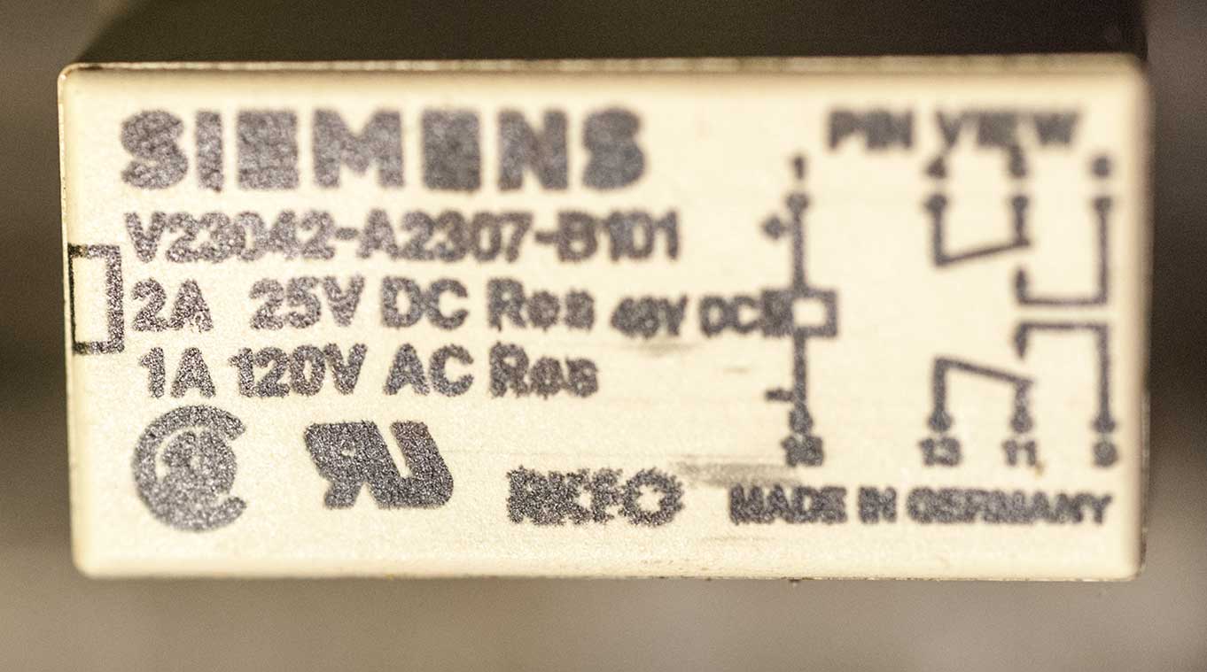
[S]suche Relais SIEMENS V23042-A2307-B101 48 V DC Spulenspannung
suche Relais SIEMENS V23042-A2307-B101 48 V DC Spulenspannung für Einbau in mein AC-Millivoltmeter MV-21. Gruß Horst
-
 Bild
Bild
Aufkleber eines Siemens Relais
SIEMENS V23042-A2307-B101 2A 25V DC Res 48V DC 1A 120V AC Res PIN VIEW MADE IN GERMANY
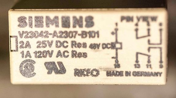
-
 Bild
Bild
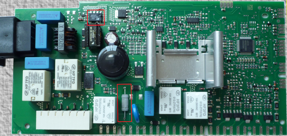
Bestückte grüne Leiterplatte mit elektronischen Bauteilen
HF7FD 012-TF7F(578) TF7FD CHINA 101 012-TF7F(578) HF3FD 012-TF7F(578) HF3FD 012-TF7F(578) 10A 200VAC 50/60Hz 85°C CHINA EPCD5 50/60Hz 00PT1 102Y20 L X
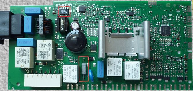
-
Thread
Parkside Lötstation
https://youtu.be/aZ3a8yKaP4Y?si=XsGRNwbOR_q-nann Vergleich mit vielen Erklärungen. Für die Profis zu langatmig, aber für Einsteiger sicher lehrreich. Parkside Fazit aber schon bei 3:20
Tom A. schrieb im Beitrag #7717741: > Interessant Meinst Du das Wort "Regelbar"?
-
 Bild
Bild
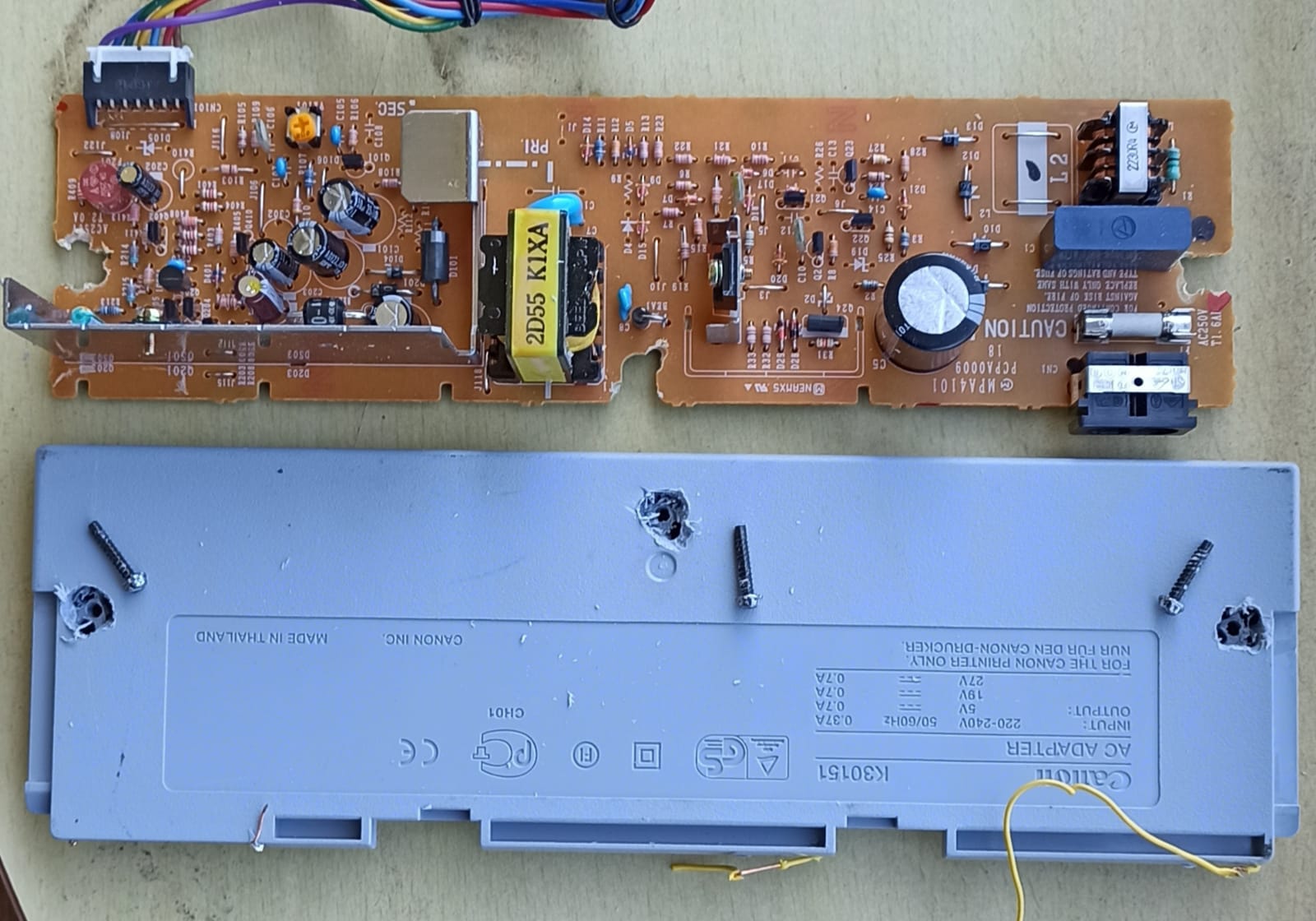
Canon AC-Adapter Platine und Gehäuse
CH101, SEC, PRI, 2D55 K1XA, CAUTION, PCPA0009, CH1, AC 24V, 1A, FOR THE CANON PRINTER ONLY, NUR FÜR DEN CANON DRUCKER, MADE IN THAILAND, CANON INC., INPUT: 220-240V 50/60HZ, OUTPUT: 27V 18V 5V 0.7A 0.7A 0.7A 0.37A, K30151, Canon
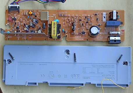
-
 Bild
Bild
CAD-Darstellung von zwei integrierten Schaltkreisen
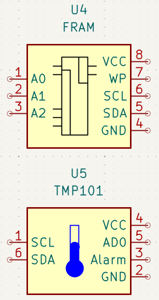
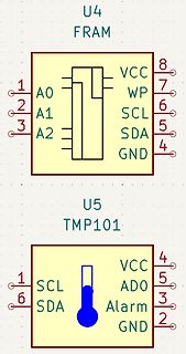
U4 FRAM 1 A0 2 A1 3 A2 8 VCC 7 WP 6 SCL 5 SDA 4 GND U5 TMP101 1 SCL 6 SDA 4 VCC 5 ADO 3 Alarm 2 GND
-
Thread
Balancer Li Ion 3S mit 4,15V / 12,6V Abschaltung
Ladegerät abschaltet nachdem kein Strom mehr fließt. So haben die Zellen eine Endspannung von ca 4,1V bei 5A Ladestrom. Ungeeignet für 100mA Ladestrom, Endspannung 4,26V.
Harald G. schrieb im Beitrag #7689125: > Ja Platine kommt mit Anlaufstrom klar. Habe den von 25A auf 50A > höhergesetzt, da er zuführen abgeschaltet hatte, wenn man den Schrauber > mal ordentlich belastet hatte. Wie setzt man die Platine von 25A auf 50A ohne weitere Nebeneffekte hoch? >
-
Thread
Kompressor für Campingkühlschrank - elektrischer Anschluss?
https://www.skh-kaeltetechnik.de/mediafiles/Sonstiges/Danfoss%20Secop/bdf101n.pdf
. Ohne einen Widerstand im Steuerkreis läuft der Verdichter mit elektronischer Steuerungseinheit 101N0210 oder 101N0220 mit einer Festdrehzahl von 2.000 min -1 , wenn der Ther- mostat eingeschaltet wird. Wird bei der elektronischer Steuerungseinheit 101N0300 der Thermostat ohne Widerstand an C
-
Thread
welche PA für QO-100 uplink?
/1995, ebenfalls von Eisch-Kafka. Ewalds Bauanleitung findet man im DUBUS-Buch Technik IV ab S. 101
auf einem neueren Stand: https://www.mikrocontroller.net/articles/QO-100_der_erste_geostation%C3%A4re_Amateurfunkumsetzer#Sendeendstufe die englische Übersetzung am Ende des Artikels fehlt noch.
-
Thread
3 ohmsche Verbraucher (je 16A) abwechseln elektrisch sicher schalten
Schaltung nicht richtig funktioniert und damit evtl. 2 oder 3 Schütze einschaltet und damit die Last auf 32A oder sogar 36A steigt. Genügt es für diesen Fall um ein elektrisch sicheres System zu haben einen 16A Leitungsschutzschalter in die Versorgungsleitung der Schütze zu setzen, der für eine Trennung sorgt
Vorschlag Nr 2 (Umschalter in Stufen): -------------------------------------- 1 Umschaltschütz z.B. 25A schaltet die zwischen Verbraucher 1 und einem weiteren 25A Umschaltschütz. An diesem hängt Verbraucher 2 und wieder ein 25A Umschaltschütz. An diesem hängt Verbraucher 3. Der Mikroprozessor schaltet
-
 Bild
Bild
Bestückte blaue Leiterplatte mit Mikrocontroller
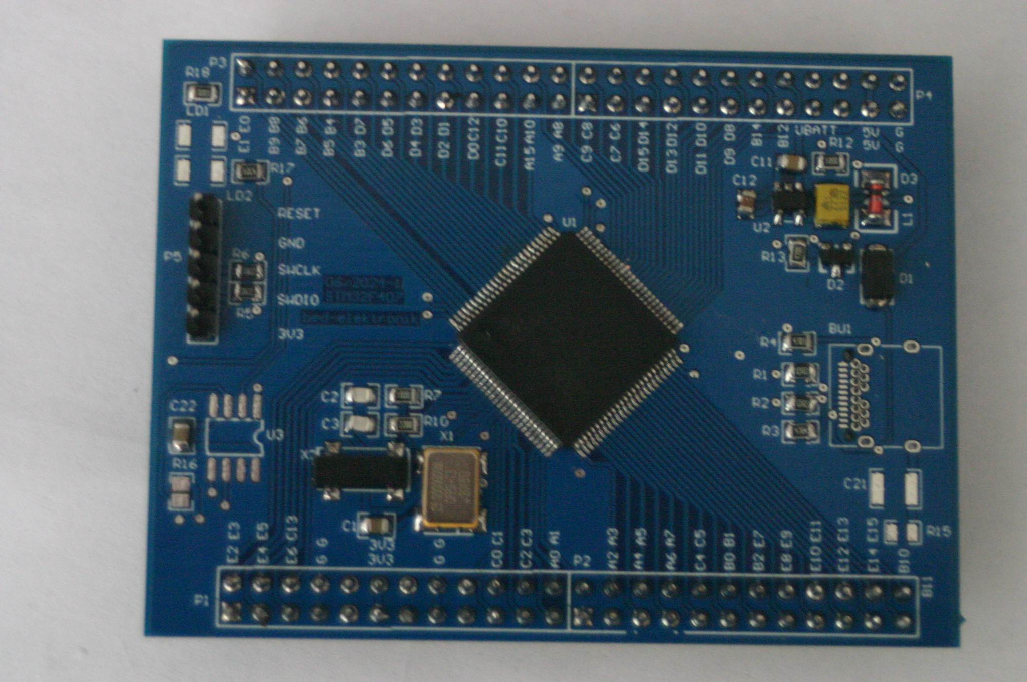
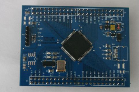
P3 R18 LD1 03 13 B9 B8 B7 B6 B5 B4 B3 B2 B1 02 01 C11 C10 A15 A9 C8 C7 C6 C5 C4 C3 C2 C1 01 010 011 012 UBATT R12 5V G 5V G D3 C11 C12 U2 R13 D2 D1 P5 R6 SWCLK 06-2021-1 SWDIO 3U3 3U3 C2 C22 E3 E3 E4 E5 E13 E12 E11 E10 E9 E8 E7 E6 E5 E4 E3 E2 E1 B10 B11 B12 B13
-
Thread
ESP32: SPIRAM wird nicht gefunden (?)
factory factory app 00 00 00020000 00100000 I (97) boot: End of partition table I (101) esp_image: segment 0: paddr=00020020 vaddr=3f400020 size=0d2a4h ( 53924) map I (124) esp_image: segment 1: paddr=0002d2cc vaddr=3ffb0000 size=02d4ch ( 11596) load I (127) esp_image: segment 2: paddr
(274) heap_init: At 3FFB3C18 len 0002C3E8 (176 KiB): DRAM I (280) heap_init: At 3FFE0440 len 00003AE0 (14 KiB): D/IRAM I (287) heap_init: At 3FFE4350 len 0001BCB0 (111 KiB): D/IRAM I (293) heap_init: At 4008F094 len 00010F6C (67 KiB): IRAM I (300) spi_flash: detected chip: generic I (304) spi_flash
-
Artikel
IRMP
' 0x0018 'i' 0x0028 'ö' 0x0038 0x0048 0x0058 0x0068 0x0078 FAVORITES 0x0009 '8' 0x0019 'o' 0x0029 'ä' 0x0039 SHIFT_RIGHT 0x0049 0x0059 RIGHT 0x0069 0x0079 NEW_PAGE 0x000A '9' 0x001A 'p' 0x002A '#' 0x003A CTRL 0x004A 0x005A 0x006A 0x007A SETUP 0x000B '0' 0x001B 'ü' 0x002B CR 0x003B 0x004B INSERT 0x005B
------ 000 0 Ausschalten 001 0 Einschalten 001 1 Kuehlen 010 1 Lueften 011 1 Entfeuchten 100 1 ??? 101 1 --- 110 1 --- 111 1 --- A = Automatik-Programm A ---------- 0 aus 1 ein t = Timer t x y ---------- 1 1 0 Timer 1 1 0 1 Timer 2 Um die Klimaanlage mittels IRSND anzusteuern, kann man folgende Funktionen
-
Thread
Unbekannter Geräteeinschub (Impulszähler)
erlebt haben. Ein weiteres Projekt ist eine Dekatron-Uhr mit den ehemals sowjetischen OG 3 und A101 (siehe Bilder in der Anlage). Da habe ich sehr lange dran gewerkelt. Final ist mir das sehr gut gelungen. logiker_61
daran, dass bestimmte Signalpegel an der dekadischen Zählerbaugruppe nicht vorhanden sind (RESET o.ä.). Die Schaltung davon habe ich noch nicht aufgenommen. Es bleibt damit weiterhin spannend. logiker_61
-
 Bild
Bild
Foto einer Leiterplatte mit Bestückungsdruck
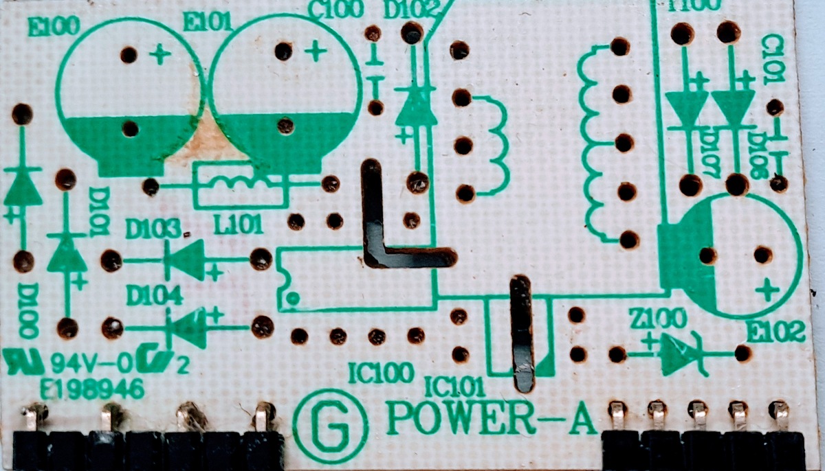
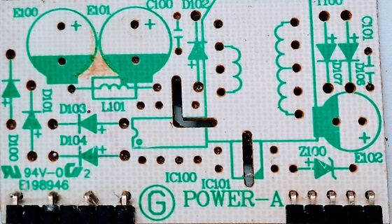
E100 E101 C100 D102 D107 D106 D101 D103 D104 L101 94V-0 2 E198946 IC100 IC101 Z100 E102 POWER-A
-
 Bild
Bild
Nahaufnahme einer bestückten Leiterplatte eines Netzteils
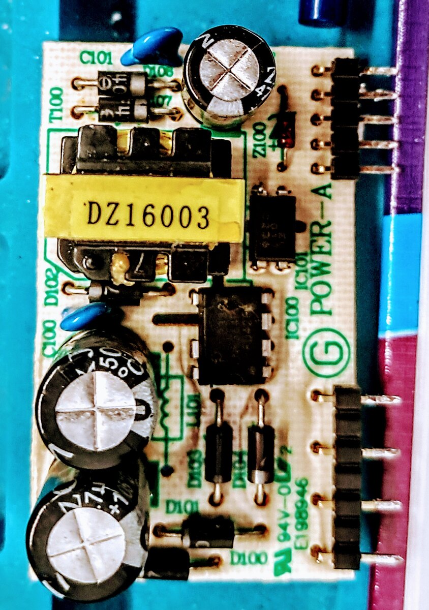
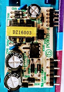
C101, D106, T100, Z100, DZ16003, IC101, IC100, POWER-A, 50°C, D102, D103, D101, D100, 94V-0, E198946
-
Thread
Bauteil-News: Entwicklerboards, Elektromechanik und vieles andere mehr
gelangen. 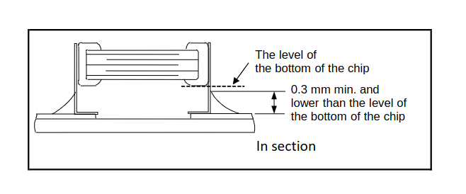 Bildquelle: https://search.murata.co.jp/Ceramy/image/img/A01X/G101/ENG/KRT31_X6S_35V_E.pdf Sinn dieser Vorgehensweise ist die Isolierung der Kondensatoren von Torsionen der Platine. Die als Bildquelle angeführte PDF-Datei bietet weitere Informationen zu dieser
besteht. Im Datenblatt verspricht das Unternehmen dabei folgende Performance: [c] Deliver 3.3 V at 60 mA from a single Alkaline/ Ni-MH or 3.3 V at 120 mA from two cells Up to 94% efficiency [/c] Im Bereich des Schaltungs-Designs ist der im SOT 23-Format vorliegende Regler ebenfalls nicht besonders
-
 Bild
Bild
Nahaufnahme einer bestückten Leiterplatte mit IC und LED
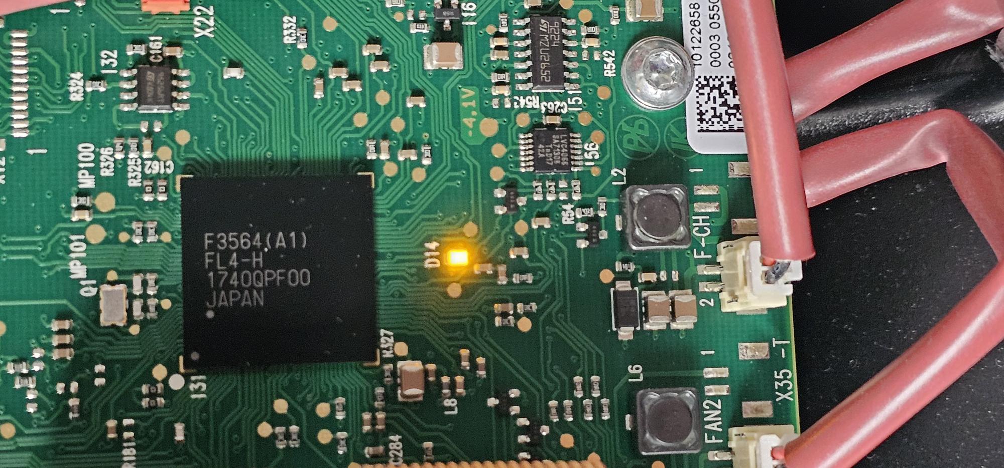
MP101 R326 MP100 R324 132 R181 C161 131 C162 X22 F3564(A1) JAPAN 17400PF00 R332 R327 C284 D14 -4,1V 116 R54 151 R542 L8 L6 L2 56 FAN2 1 2 F-CH X35 -T 1012658 0003 0550