-
Datei
Schwebekugel.c
include <avr/eeprom.h> #include <avr/pgmspace.h> #include <util/delay.h> #include <avr/interrupt.h> int32_t wmax; int32_t wmin; /******************************Schwebekugel**************************/ /************************Für ATMEGA8 bei 8MHz Takt*******************/ void delay (uint64_t n) {uint32_t x
in „Schwebende Kugel“ · Analoge Elektronik und Schaltungstechnik ·
-
 Bild
Bild
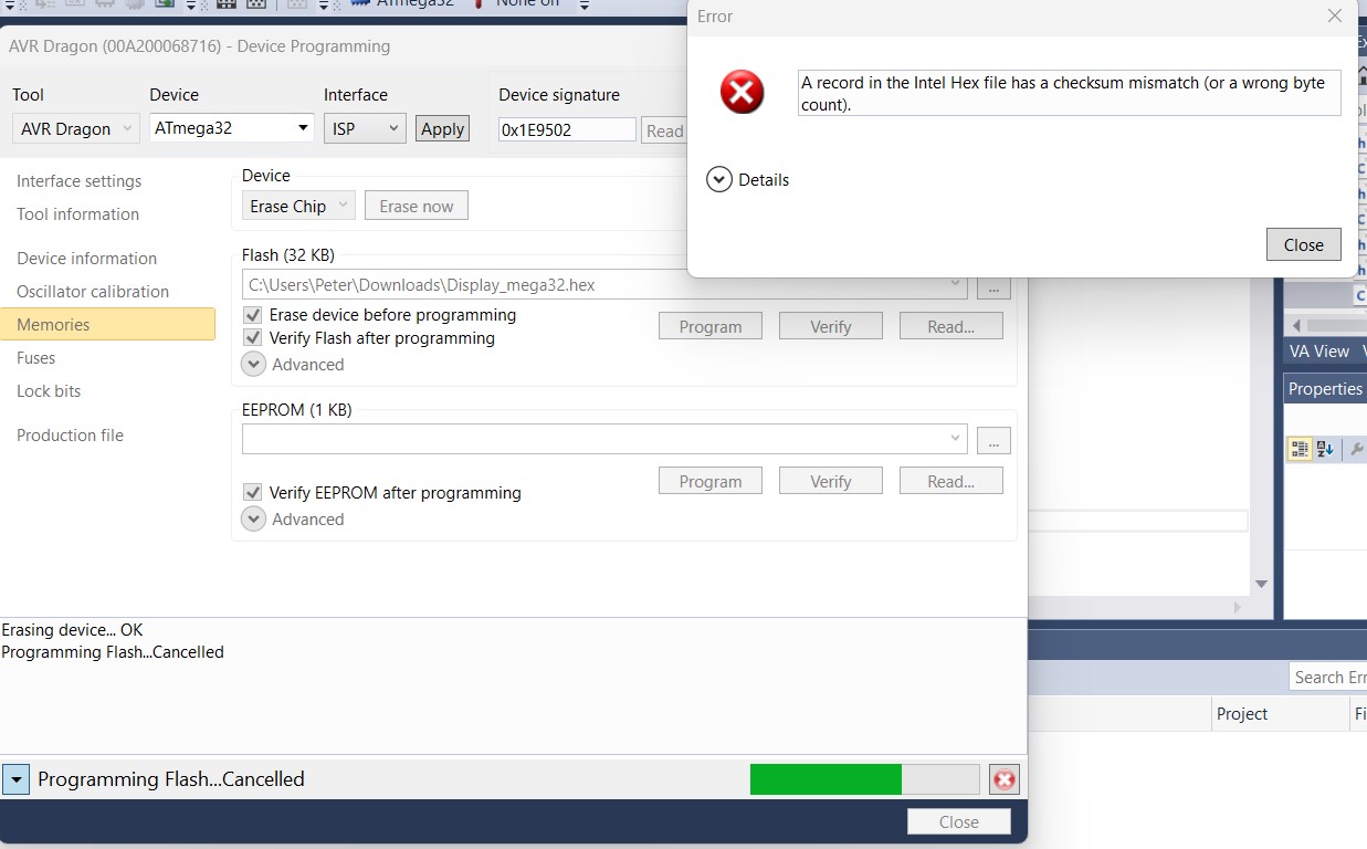
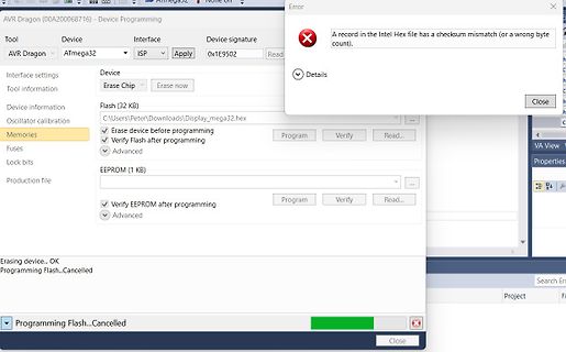
Fehlermeldung beim Programmieren eines AVR-Mikrocontrollers
byte count). Details Close AVR Dragon (00A200068716) - Device Programming Tool AVR Dragon Device ATmega32 Interface ISP Apply Device signature 0x1E9502 Read Device Erase Chip Erase now Interface settings Flash (32 KB) C:\Users\Peter\Downloads\Display_mega32.hex Erase device before programming Verify
in „Hex File von Atmega16 in Atmega32 verwandeln“ · Mikrocontroller und Digitale Elektronik · · Screenshots
-
Datei
main.c
/********************************************* Project : Heizung ATmega32 Version : 2.3 Date : 09.12.2003 // AT90C8535 Date : 08.01.2006 // ATMEGA32 Date : 29.11.2006 // Fehler im Taktgenerator (Uhr ging falsch) Date : 03.10.2010 // 3. KTY81 für Rücklauf, 2x20 LCD, Zündungszähler Author : (c) Holger Buss http://www.mikrocontroller.com --> Bauanleitungen Chip type : ATmega32 Program type : Application Clock frequency : 8,000000 MHz Memory model : Small External SRAM size : 0 Data Stack size : 512 *********************************************/ #define EXTRA_MENU //#define
in „Heizungssteuerung mit ATMEGA 32“ · Mikrocontroller und Digitale Elektronik ·
-
Datei
Laufschr.asm
========== Tabellen ================================= ; text001: ; Konstanten der Festtexte .db "ATMEGA8_________",0 ; mit Nullterminierung text002: .db "_ATMEGA8________",0 text003: .db "__ATMEGA8_______",0 text004: .db "___ATMEGA8______",0 text005: .db "____ATMEGA8_____",0 text006: .db "_____ATMEGA8____",0 text007: .db "______ATMEGA8___",0 text008: .db "_______ATMEGA8__",0 text009: .db "________ATMEGA8_",0 text010: .db "_________ATMEGA8",0 text011: .db "__________ATMEGA",0 text012: .db "___________ATMEG",0 text013: .db "______
in „LCD Lauftext Atmega8“ · Mikrocontroller und Digitale Elektronik ·
-
Datei
main.c
<avr/eeprom.h> #include <avr/wdt.h> #include <math.h> //AVR-Typenabhänggikeit #if defined(__AVR_ATmega48__) #define MCU_STATUS_REG MCUCR #elif defined(__AVR_ATmega88__) #define MCU_STATUS_REG MCUCR #define UseM8 #elif defined(__AVR_ATmega168__) #define MCU_STATUS_REG MCUCR #define UseM8 #else #define
-
Datei
uart.asm
- ; Konstanten und Registerdefinitionen ; ----------------------------------- ; .nolist .include "m32def.inc" .list ; ; Festwerte definieren ; .equ clock = 8000000 ;Controller Taktfrequenz= 8,0MHz .equ baud = 9600 ;RS-232 Baudrate= 9600 38400 .equ UBRRVAL = CLOCK/(BAUD*16)-1 ; ; REGISTER definieren ;
-
Datei
DMX-Tranciever.asm
/*DMX Sender mit einem AVR nach Julien Mintenbeck + Hendrik Hölscher für ATmega8515 */ //DEFINES************************************************************************* .INCLUDE "M32DEF.INC" .DEVICE ATmega32 .DEF S_save = R2 //SREG Puffer .DEF temp = R16 //standart .DEF tempH
in „Problem bei DMX-Sender mit einem AVR“ · Mikrocontroller und Digitale Elektronik ·
-
Datei
main.c
/* Eine 8-kanalige PWM mit intelligentem Lösungsansatz ATmega32 @ 8 MHz */ // Defines an den Controller und die Anwendung anpassen #define F_CPU 16000000L // Systemtakt in Hz #define F_PWM 100L // PWM-Frequenz in Hz #define PWM_PRESCALER 8 // Vorteiler für den
in „PWM Programm erweitern“ · Mikrocontroller und Digitale Elektronik ·
-
Datei
test_lcd.c
Wl,-Tdata=0x800500 -Wl,--defsym,__DATA_REGION_ORIGIN__=0x800500 -Wl,--defsym=__DATA_REGION_LENGTH__=32k -mmcu=atmega162 -o "Strings_im_Flash.elf" ./test_lcd.o Finished building target: Strings_im_Flash.elf Invoking: AVR Create Extended Listing avr-objdump -h -S Strings_im_Flash.elf >"Strings_im_Flash.lss
in „Fehlermeldung: near initialization for“ · Mikrocontroller und Digitale Elektronik ·
-
PDF
Schematic_ATMEGA_CaN_L298_2020-04-23_23-39-20.pdf
GND 9 VSS 5V 1 2 valveClose valveOpen 3 4 GND L298_OUT1 5 6 L298_OUT2 7 8 L298_OUT4 L298_OUT3 9 10 ATMEGA328 ATMEGA328 5V ATMEGA328P-AU B 1 32 L298_IN4 R4 B L298_ENB 2(PCINT19/OC2B/INT1)PD3 PD2(INT0/PCINT18)31 TX 10K ABSTANDSENSOR C2 WS2812_LED 3(PCINT20/XCK/T0)PD4 PD1(TXD/PCINT17) 30 RESET Header-Male
in „atmega328 - arduino bootloader flashen - doppelt belegte Pins“ · Platinen ·
-
Datei
uart_RN_test.c
io.h> //Einbinden der Portpins und des richtigen µC, µC muß noch definiert werden #include <avr/iom32.h> #include <avr/wdt.h> //*********************************************************************************** #define __AVR_ATmega32__ //µC MEGA 32 eingestellt #ifndef F_CPU #define F_CPU 8000000UL /
in „Empfangen mit dem Microcontroller“ · Mikrocontroller und Digitale Elektronik ·
-
Datei
PWM.c
******************************** */ /********************************************* * Chip type : ATMEGA32 * Clock frequency : clock 16 MHz *********************************************/ #include <avr/io.h> #include <inttypes.h> #include <string.h> #include "disp.h" uint32_t ReadChannel(uint8_t mux) { uint16_t i; uint32_t result; uint32_t result2; ADMUX = mux; // Kanal waehlen ADMUX = (1<<REFS0) | (0<<REFS1); // ADCVCC=ADCVREF ADCSRA = (1<<ADEN)|(1<<ADPS0)|(1<<ADPS1)|(1<<ADPS2); // Frequenzvorteiler // setzen auf 128
in „Gemessene Spannung ungleich ADC-Wert“ · Mikrocontroller und Digitale Elektronik ·
-
Datei
PWM.c
******************************** */ /********************************************* * Chip type : ATMEGA32 * Clock frequency : clock 16 MHz *********************************************/ #include <avr/io.h> #include <inttypes.h> #include <string.h> #include "disp.h" uint32_t ReadChannel(uint8_t mux) { uint16_t i; uint32_t result; uint32_t result2; ADMUX = mux; // Kanal waehlen ADMUX = (0<<ADLAR)|(1<<REFS0) | (0<<REFS1); // ADCVCC=ADCVREF ADCSRA = (1<<ADEN)|(1<<ADPS0)|(1<<ADPS1)|(1<<ADPS2); // Frequenzvorteiler // setzen
in „Leider noch immer keine Lösung mit ADC“ · Mikrocontroller und Digitale Elektronik ·
-
Datei
RIBU_M8_LCD_MCP9801.bas
**************************************** 30.06.2005 *********** '* A V R - B E I S P I E L E für ATMega8-Testboard * '* Copyright 1988-2005 RIBU Elektronik Versand * '* * '* Dieses Beispiel liest den Wert vom Temperatursensor MCP9801 aus und zeigt * '* den Werte auf dem LCD-Display an. * '***********
in „Nicht nachvollziehbares Verhalten beim Programmieren“ · Mikrocontroller und Digitale Elektronik ·
-
Datei
main.c
wird */ { // hier sollte der Code stehen } // Globale Variablen definieren uint16_t DACWert = 0; uint32_t ADCWert0 = 0; uint32_t ADCWert1 = 0; char LEER[] = " "; int main (void) { // Ein-/Ausgänge initialisieren // Datenrichtung Ausgang DDRD |= (1 << DDD3); // LED DDRC |= (1 << DDC0); // Sync_nicht, DAC
in „ADC LTC2436 an Atmega8, in C“ · Mikrocontroller und Digitale Elektronik ·
-
Datei
main.c
--------------------------------------------------------- */ /* $Id: twitest.c,v 1.6 2005/11/05 22:32:46 joerg_wunsch Exp $ */ /* * Simple demo program that talks to a 24Cxx I²C EEPROM using the * builtin TWI interface of an ATmega device. */ #include <inttypes.h> #include <stdio.h> #include <stdlib.h
in „IS24C01B I2C ATmega 16“ · Mikrocontroller und Digitale Elektronik ·
-
Datei
TMC222_AVR.c
library for using a TMC222 together with AVR processors that have a hardware TWI interface (e.g. ATmega8, ATmega48, ATmega88, ATmega168, ATmega16, ATmega32, ATmega64, ATmega128, AT90CAN128 and many more). It implements and interrupt driven TWI master communication over the TWI of the AVR MCU and utilizes
in „Ansteuerung TMC222“ · Mikrocontroller und Digitale Elektronik ·
-
Datei
TMC222_AVR.c
library for using a TMC222 together with AVR processors that have a hardware TWI interface (e.g. ATmega8, ATmega48, ATmega88, ATmega168, ATmega16, ATmega32, ATmega64, ATmega128, AT90CAN128 and many more). It implements and interrupt driven TWI master communication over the TWI of the AVR MCU and utilizes
in „ELV USB-I2C & Schrittmotorsteuerung iSMT“ · Mikrocontroller und Digitale Elektronik ·
-
Datei
twitest.c
--------------------------------------------------------- */ /* $Id: twitest.c,v 1.6 2005/11/05 22:32:46 joerg_wunsch Exp $ */ /* * Simple demo program that talks to a 24Cxx I²C EEPROM using the * builtin TWI interface of an ATmega device. */ #include <inttypes.h> #include <stdio.h> #include <stdlib.h
in „Die I2C Schnittstelle eines PIC16F876A initialisieren“ · Mikrocontroller und Digitale Elektronik ·
-
Datei
debug_okay.asm
<acquire_DHT+0x1b6> 328: 42 c0 rjmp .+132 ; 0x3ae <acquire_DHT+0x23a> 32a: 01 2e mov r0, r17 32c: 01 c0 rjmp .+2 ; 0x330 <acquire_DHT+0x1bc> 32e: 22 0f add r18, r18 330: 0a 94 dec r0 332: ea f7 brpl .-6 ; 0x32e <acquire_DHT+0x1ba> 334: 30 91 04 01 lds r19, 0x0104 338: 32
in „Fehler bei einfacher Integer-Division?“ · Mikrocontroller und Digitale Elektronik ·
-
Datei
test_lcd_2.c
"lcd.h" /* ** constant definitions */ #ifndef CTC1 #define CTC1 WGM12 // for compatibility with ATmega #endif #define PHASE_A (PINC & 1<<PINC2) // PINC.2 #define PHASE_B (PINC & 1<<PINC3) // PINC.3 #define PHASE_E (PINC & 1<<PINC5) // PINC.5 #define ESECT __attribute__((section(".eeprom"))) uint8_t eeprom_var1 ESECT = 1; int32_t state1; int32_t standard = 738; // Friday, 24th May int32_t minutes = 0; int32_t seconds = 0; int stellen = 0; int screen = 0; volatile char enc_delta; // -128 ... 127 /* ** function prototypes */
in „Drehregler an uC - geht das?“ · Mikrocontroller und Digitale Elektronik ·
-
Datei
test_lcd_3.c
"lcd.h" /* ** constant definitions */ #ifndef CTC1 #define CTC1 WGM12 // for compatibility with ATmega #endif #define PHASE_A (PINC & 1<<PINC2) // PINC.2 #define PHASE_B (PINC & 1<<PINC3) // PINC.3 #define PHASE_E (PINC & 1<<PINC5) // PINC.5 #define ESECT __attribute__((section(".eeprom"))) uint8_t eeprom_var1 ESECT = 1; int32_t state1; int32_t standard = 738; // Friday, 24th May int32_t minutes = 0; int32_t seconds = 0; int stellen = 0; int screen = 0; /* ** function prototypes */ SIGNAL (SIG_OUTPUT_COMPARE2) { static uint16
in „Drehregler an uC - geht das?“ · Mikrocontroller und Digitale Elektronik ·
-
Datei
Test-_Code.txt
#include <mega32.h> #include <stdio.h> #include <T6963.c> #include <draw.c> // Declare your global variables here char i; char data[17]; // Timer 2 overflow interrupt service routine interrupt [TIM2_OVF] void timer2_
in „ATMEGA32 Interrupt“ · Mikrocontroller und Digitale Elektronik ·
-
Datei
error1.txt
avr-gcc -mmcu=atmega32 -Wall -Werror -Wstrict-prototypes -Os -mcall-prologues -DF_CPU=3686400 -DF_CAN=8000000 -DCAN_SPEED=125000 -I. -I../../canix -I../.. -I../../include -DMCU_atmega32 -DCANIX_SYSLOG -DCANIX_HMS -DCANIX_RTS
in „gcc-avr geht nicht unter debian 4.0“ · Mikrocontroller und Digitale Elektronik ·
-
Datei
tm16xx.h
Tasteninterface. Geeignet fuer: TM1651, TM1637 MCU : alle AVR ( getestet ATtiny85, ATtiny2313, ATtiny44, ATmega8, ATmega328p ) F_CPU : 8 MHz intern Pinbelegung Controller TM16xx --------------------------- PB1 CLK PB0 DIO CLK und DIO sind mit jeweils 2,2 kOhm Pop-Up Wider- staenden nach +5V zu versehen 10.01.2019
in „Siebensegment und Tasten ansteuern mit TM1651 \ TM1637“ · Projekte & Code ·
-
Datei
DZM_BIG_TEST.bas
$regfile = "M8def.dat" 'Set the chip type to ATmega8 $crystal = 8000000 '8 Mhz Prozessortakt an PB6 Config Timer1 = Timer , Prescale = 1 , Capture Edge = Rising Ddrb = &B11111110 'Pin PB0 Signal-Eingang Portb = &B00000001 'pull-up von PB0 aktivieren
in „LCD Anzeige für KFZ“ · Mikrocontroller und Digitale Elektronik ·
-
Datei
FrequencyCounterUno5.ino
PIND&0b00100000)!=0) uint16_t OldValueTimer1 = 0; #define TIMEOUT_NUM 1000000 boolean measureTime(uint32_t *tLow, uint32_t *tHigh) { uint32_t timeOut; uint32_t t1, t2, t3, t4; //pinMode(READ_INPUT_TIMER1,INPUT); timeOut = TIMEOUT_NUM; // wait for rising edge //while (timeOut > 0 && digitalRead(PIN_COUNTER_INPUT
-
Datei
macros.inc
EPILOGUE_RESTORES(offset) XJMP (__epilogue_restores__ + 2 * (offset)) #if FLASHEND > 0x10000 /* ATmega103 */ #define BIG_CODE 1 #else #define BIG_CODE 0 #endif /* Smart version of movw (use register numbers as arguments): - uses "movw" if possible (supported by MCU, and both registers even) - handles
-
 Bild
Bild
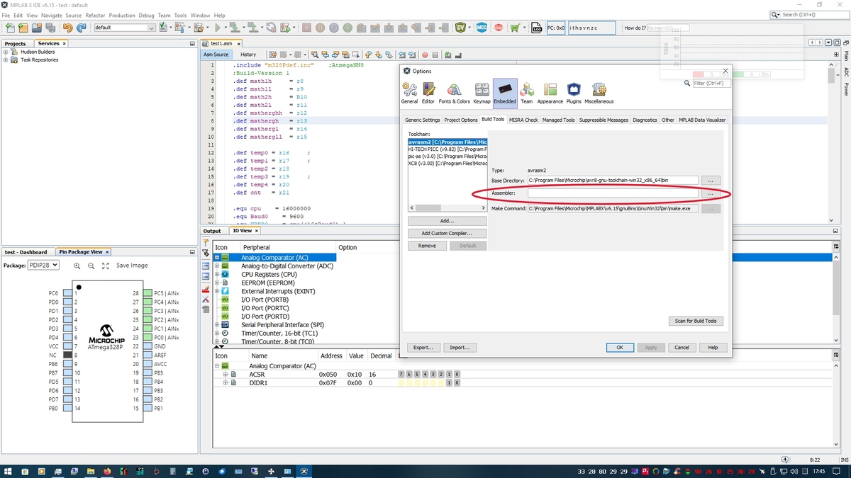
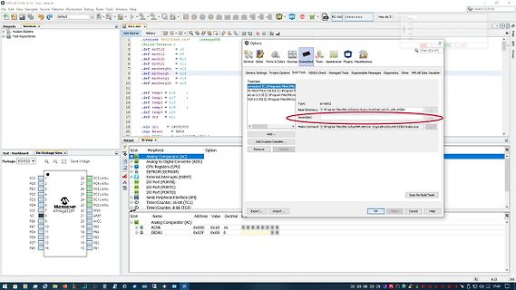
Code-Editor mit AVR Studio Projektansicht
test.asm, #include "m32def.inc", ATmega328P, Build-Version 1, Assembler, Analog Comparator (AC), ATmega328P
in „MPLAB X IDE AVR in ASM“ · Mikrocontroller und Digitale Elektronik · · Screenshots
-
Datei
adc.c
#include <mega8.h>; // Include Datei für den ATMega8 #include <delay.h>; // Include Datei für die Verzögerungsfunktion void main() { int sample,i,value; // Variablen definitionn DDRB=0xFF; // PORTB als Ausgabeport ADMUX=0x00; // ADC Ref auf Avcc, PC0
in „AVR ATMega8 einfacher ADC Test (ANSI C)“ · Projekte & Code ·
-
PDF
an131f.pdf
below. // OLIVER.C: // // Hot temps from a jar of olives. // // The microprocessor is the Atmel ATmega32U4. See ‘atmel.com’ for its // datasheet. The code is compiled with the current version of the // ‘avr-gcc’ compiler obtainable at ‘winavr.sourceforge.net’. // // Calibration data: // Pulse len (usecs
in „Acoustic Thermometry: Temperaturmessung über die Schallgeschwindigkeit (Letzte AN von Jim Williams)“ · Projekte & Code ·
-
 Bild
Bild
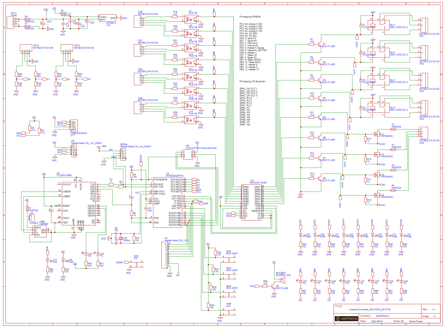
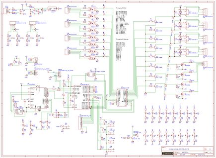
Schaltplan einer Mikrocontroller-Steuerung
ATMEGA32A, ATMEGA328P, 10uF, 100nF, 10k, 4.7k, 1k, 220, 100, 1k, 470, 1k, 1k, 1k, 1k
in „Atmega328-Platine, wo hab ich den Fehler?“ · Mikrocontroller und Digitale Elektronik · · Schaltpläne
-
Datei
Belegung_Atmega_RFM12.txt
Belegung Atmega 16/32 und RFM12 NINT/VDI > 1 (Pin Atmega) DCLK > 17 FSK > 4 NSEL > 5 SDI > 6 SDO > 7 SCK > 8 NIRQ > 16
in „Bascom und RFM12 Modul Problem“ · Mikrocontroller und Digitale Elektronik ·
-
Datei
m8def.inc
I L Y ;* ;* Number :AVR000 ;* File Name :"m8def.inc" ;* Title :Register/Bit Definitions for the ATmega8 ;* Date :07.09.2001 ;* Version :1.00 ;* Support telephone :+47 72 88 43 88 (ATMEL Norway) ;* Support fax :+47 72 88 43 99 (ATMEL Norway) ;* Support E-mail :avr@atmel.no ;* Target MCU :ATmega8 ;* ;
-
Datei
m8def.inc
I L Y ;* ;* Number :AVR000 ;* File Name :"m8def.inc" ;* Title :Register/Bit Definitions for the ATmega8 ;* Date :07.09.2001 ;* Version :1.00 ;* Support telephone :+47 72 88 43 88 (ATMEL Norway) ;* Support fax :+47 72 88 43 99 (ATMEL Norway) ;* Support E-mail :avr@atmel.no ;* Target MCU :ATmega8 ;* ;
-
Datei
m8def.inc
I L Y ;* ;* Number :AVR000 ;* File Name :"m8def.inc" ;* Title :Register/Bit Definitions for the ATmega8 ;* Date :07.09.2001 ;* Version :1.00 ;* Support E-mail :avr@atmel.no ;* Target MCU :ATmega8 ;* ;* DESCRIPTION ;* When including this file in the assembly program file, all I/O register ;* names and
-
Datei
m8def.inc
I L Y ;* ;* Number :AVR000 ;* File Name :"m8def.inc" ;* Title :Register/Bit Definitions for the ATmega8 ;* Date :07.09.2001 ;* Version :1.00 ;* Support telephone :+47 72 88 43 88 (ATMEL Norway) ;* Support fax :+47 72 88 43 99 (ATMEL Norway) ;* Support E-mail :avr@atmel.no ;* Target MCU :ATmega8 ;* ;
in „Illegal device name“ · Mikrocontroller und Digitale Elektronik ·
-
Datei
m8def.inc
I L Y ;* ;* Number :AVR000 ;* File Name :"m8def.inc" ;* Title :Register/Bit Definitions for the ATmega8 ;* Date :07.09.2001 ;* Version :1.00 ;* Support E-mail :avr@atmel.no ;* Target MCU :ATmega8 ;* ;* DESCRIPTION ;* When including this file in the assembly program file, all I/O register ;* names and
in „Fehlermeldung beim Assemblieren“ · Mikrocontroller und Digitale Elektronik ·
-
Datei
m8def.inc
I L Y ;* ;* Number :AVR000 ;* File Name :"m8def.inc" ;* Title :Register/Bit Definitions for the ATmega8 ;* Date :07.09.2001 ;* Version :1.00 ;* Support telephone :+47 72 88 43 88 (ATMEL Norway) ;* Support fax :+47 72 88 43 99 (ATMEL Norway) ;* Support E-mail :avr@atmel.no ;* Target MCU :ATmega8 ;* ;
in „Include Datei für Atmega8“ · Mikrocontroller und Digitale Elektronik ·
-
Datei
m8def.inc
I L Y ;* ;* Number :AVR000 ;* File Name :"m8def.inc" ;* Title :Register/Bit Definitions for the ATmega8 ;* Date :07.09.2001 ;* Version :1.00 ;* Support telephone :+47 72 88 43 88 (ATMEL Norway) ;* Support fax :+47 72 88 43 99 (ATMEL Norway) ;* Support E-mail :avr@atmel.no ;* Target MCU :ATmega8 ;* ;
in „m8def.inc runterladen“ · Mikrocontroller und Digitale Elektronik ·
-
Datei
m8def.inc
I L Y ;* ;* Number :AVR000 ;* File Name :"m8def.inc" ;* Title :Register/Bit Definitions for the ATmega8 ;* Date :07.09.2001 ;* Version :1.00 ;* Support telephone :+47 72 88 43 88 (ATMEL Norway) ;* Support fax :+47 72 88 43 99 (ATMEL Norway) ;* Support E-mail :avr@atmel.no ;* Target MCU :ATmega8 ;* ;
in „m8def.inc runterladen“ · Mikrocontroller und Digitale Elektronik ·
-
Datei
m8def.inc
I L Y ;* ;* Number :AVR000 ;* File Name :"m8def.inc" ;* Title :Register/Bit Definitions for the ATmega8 ;* Date :07.09.2001 ;* Version :1.00 ;* Support E-mail :avr@atmel.no ;* Target MCU :ATmega8 ;* ;* DESCRIPTION ;* When including this file in the assembly program file, all I/O register ;* names and
in „Peter Danneggers Bootloader (fastboot) für AVR-GCC-Toolchain“ · Projekte & Code ·
-
Datei
m8def.inc
I L Y ;* ;* Number :AVR000 ;* File Name :"m8def.inc" ;* Title :Register/Bit Definitions for the ATmega8 ;* Date :07.09.2001 ;* Version :1.00 ;* Support telephone :+47 72 88 43 88 (ATMEL Norway) ;* Support fax :+47 72 88 43 99 (ATMEL Norway) ;* Support E-mail :avr@atmel.no ;* Target MCU :ATmega8 ;* ;
in „Ich bräuchte mal Starthilfe.“ · Mikrocontroller und Digitale Elektronik ·
-
Datei
m8def.inc
I L Y ;* ;* Number :AVR000 ;* File Name :"m8def.inc" ;* Title :Register/Bit Definitions for the ATmega8 ;* Date :07.09.2001 ;* Version :1.00 ;* Support E-mail :avr@atmel.no ;* Target MCU :ATmega8 ;* ;* DESCRIPTION ;* When including this file in the assembly program file, all I/O register ;* names and
in „AVR ASM Timer-Interrupt“ · Mikrocontroller und Digitale Elektronik ·
-
Datei
m8def.inc
I L Y ;* ;* Number :AVR000 ;* File Name :"m8def.inc" ;* Title :Register/Bit Definitions for the ATmega8 ;* Date :07.09.2001 ;* Version :1.00 ;* Support telephone :+47 72 88 43 88 (ATMEL Norway) ;* Support fax :+47 72 88 43 99 (ATMEL Norway) ;* Support E-mail :avr@atmel.no ;* Target MCU :ATmega8 ;* ;
in „def. inc Datei“ · Mikrocontroller und Digitale Elektronik ·
-
Datei
m8def.inc
I L Y ;* ;* Number :AVR000 ;* File Name :"m8def.inc" ;* Title :Register/Bit Definitions for the ATmega8 ;* Date :07.09.2001 ;* Version :1.00 ;* Support telephone :+47 72 88 43 88 (ATMEL Norway) ;* Support fax :+47 72 88 43 99 (ATMEL Norway) ;* Support E-mail :avr@atmel.no ;* Target MCU :ATmega8 ;* ;
in „Anfänger Frage zu Assembler“ · Mikrocontroller und Digitale Elektronik ·
-
PDF
Brick_MCU_PinAssignments_ref2.pdf
8 NC NC P4-9 TDI TDI P4-10 GND GND Table 1 JTAG/Misc header pin assignment 3 AT-ANY-900/2400 vs. ATMEGA1281V vs. AT-ANY-Brick Atmega1281v Module's pin Module's Brick900/2400's number Pin name Pin number PB1 1 SCK P1-2 PB3 2 DSO P1-3 PB2 3 DSI P1-4 PB5 4 GPIO0 P1-5 PB6 5 GPIO1 P1-6 PB7 6 GPIO2 P1-7 PC4
in „LM73 über TWI/I2C mit Atmega1281 auslesen“ · Mikrocontroller und Digitale Elektronik ·
-
Datei
sndrx-bootloader.c
---------------------- * sndrx-bootloader.c * * Copyright (c) 2011 Robert Meyer, Frank Meyer * * ATMEGA168 @ 8 MHz * * This program is free software; you can redistribute it and/or modify * it under the terms of the GNU General Public License as published by * the Free Software Foundation; either version
in „SOUNDRX - Datenübertragung/Bootloader PC -> µC über PC-Soundkarte“ · Projekte & Code ·
-
PDF
Z180.pdf
9 38 C15 4 3 t 61 66 VCC RX_AVR/2.5A 10 PD0 VCC 27 10K e 65 /RFSH /WR 67 74HCT32D TX_AVR/2.4A 11 PD1 AVCC 100n 100n R /M1 /RD C14 32 U1 13 SDREQ PD2 R12 2 1 1 VCC DQ0 BUSACK 12 PD3 AREF 29 C2 C9 S A18/TOUT 33 DQ1 14 LATCH 13 PD4 ~RESET 4 AVR_RESET/3.1B A17 32 100n 22 CE DQ2 15 ZRESET
in „CP/M auf ATmega88“ · Mikrocontroller und Digitale Elektronik ·
-
 Bild
Bild
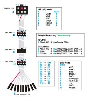
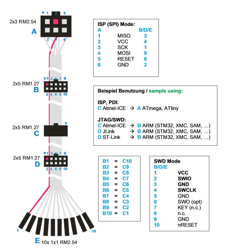
Pinbelegung ISP und SWD Adapter
2 2x5 RM1.27 B 1 3 5 7 9 2 4 6 8 10 Beispiel Benutzung / sample using: ISP, PDI: C Atmel-ICE -> ATmega, ATtiny JTAG/SWD: C Atmel-ICE -> B ARM (STM32, XMC, SAM, ...) D JLink -> B ARM (STM32, XMC, SAM, ...) D ST-Link -> B ARM (STM32, XMC, SAM, ...) 2x5 RM1.27 C 2x5 RM1.27 D B1 = C10 B2 = C9 B3 = C8 B4
in „Atmel ICE Programmer und UPDI“ · Mikrocontroller und Digitale Elektronik · · Diagramme