0.20< 1 Φ≦0.25 0.25<Φ 0 3.2 Line type : (As following drawing) Length Width Acceptable Q TY --- W≦0.02 Accept no dense 2.5 L≦3.0 0.02<W≦0.03 2 L≦2.5 0.03<W≦0.05 --- 0.05<W As round type 04 Polarizer bubbles If bubbles are visible,Size Φ Acceptable Q TY judge using black Φ≦0.20 Accept no dense spot specifications
#7851551: > Gerade Betriebsstoffe fürs Auto darf man ausdrücklich dort lagern. Begrenzt auf 20l Benzin und 200l Diesel, auch das ist in den Garagenverordnungen geregelt.
Jahr bis zu 10 cm³ Lagerraum. Günstiger gehts nicht ... " Rechenbeispiel: 750kg Kofferanhänger 3,02x1,46x1,50m : Versicherung ca. 100€ Steuern ca. 30€ Anwohner Parkplatz 0 bis 365€ pro Jahr Stauraum von ca. 7,50 qbm für 130-500€ zur Miete!
kleinen Behältern mit Federdeckel verpackt, das wird nicht billig https://www.ipit-blog.de/2022/12/02/das-maeuseklo-das-ist-grad-besetzt/
Christoph db1uq K. schrieb im Beitrag #7852090: > https://www.ipit-blog.de/2022/12/02/das-maeuseklo-das-ist-grad-besetzt/ Unglaublich, mit welchem _Scheiß_ sich die Gerichte herumschlagen müssen! Wer kommt denn allein schon auf die Idee, sich "Mäuseklo" als Marke eintragen zu lassen
description [1] Table 3. Function table Operating modes Inputs Outputs MR CP Dn Qn Qn reset (clear) L X X L H load “1” H h H L load “0” H l L H [1] H = HIGH voltage level; h = HIGH voltage level one set-up time prior to the LOW-to-HIGH clock transition; L = LOW voltage level; l = LOW voltage level
demultiplexer; inverting 6. Functional description Table 3. Function table H = HIGH voltage level; L = LOW voltage level; X = don’t care. Control Input Output E1 E2 E3 A2 A1 A0 Y7 Y6 Y5 Y4 Y3 Y2 Y1 Y0 H X X X X X H H H H H H H H X H X X X L L L H L L L H H H H H H H L L L H H H H H H H L H L H L H H H H H L H H L H H H H H H L H H H H L L H H H L H H H H H L H H H L H H H H H H H L H L H H H H H H H H H L H H H H H H H 7. Limiting values Table 4. Limiting values In accordance with the Absolute Maximum Rating
reset; positive edge-trigger 6. Functional description Table 3. Function table H = HIGH voltage level; L = LOW voltage level; X = don’t care. Input Output nSD nRD nCP nD nQ nQ L H X X H L H L X X L H L L X X H H Table 4. Function table H = HIGH voltage level; L = LOW voltage level; X = don’t care; ↑ = LOW-to-HIGH
3-input AND gate 6. Functional description Table 3. Function selection[1] Input Output nA nB nC nY L X X L X L X L X X L L H H H H [1] H = HIGH voltage level; L = LOW voltage level; X = don’t care 7. Limiting values Table 4. Limiting values In accordance with the Absolute Maximum Rating System (IEC
74HCT08 Quad 2-input AND gate 6. Functional description Table 3. Function table H = HIGH voltage level; L = LOW voltage level; X = don’t care. Input Output nA nB nY L L L L H L H L L H H H 7. Limiting values Table 4. Limiting values In accordance with the Absolute Maximum Rating System (IEC 60134). Voltages
Ambient Temperature 1.2 35 d c A m 1.0 m30 Y - I A N S m E25 E 20.8 R T T U I A C20 S D0.6 D O I E I L L15 M A A L R0.4 W E O O10 I ( L T 0.2 A L X 5 E M R 0.0 0 0 5 10 15 20 25 30 0 10 20 30 40 50 60 70 80 90 FORWARD CURRENT- mA AMBIENT TEMPERATURE, TA - °C Broadcom AV02-4479EN 11 HLCP-A100/-B100/-C100
Packaging Specification located at http://www.microchip.com/packaging 4X ș1 R1 H R c SEATING PLANE C L ș (L1) 4X ș 1 DETAIL B Units MILLIMETERS Dimension Limits MIN NOM MAX Number of Terminals N 8 e Pitch 0.65 BSC Overall Height A – – 1.10 Standoff A1 0.00 – 0.15 Molded Package Thickness A2 0.75 0.85
current VIN= VOUT= 0 V; 12 t (5 µA Tj= 25 °C c On-state;CC = 13 V;IN= 5 V; d u5 7 mA OUT = 0 A r o L(off1) Off-state output curreIN= VOUT= 0 V P 0 50 µA L(off2) Off-state output curreIN= 0V; OUT= 3.5 V e -75 0 µA e t L(off3) Off-state output currT = 125 °C 0 o; CC= 13 V; 5 µA j s L(off4) Off-state output
10896 Rev 4 VN920SP-E Electrical specifications Table 11. Truth table Conditions Input Output Sense L L 0 Normal operation H H Nominal Overtemperature L L 0 H L VSENSEH L L 0 Undervoltage H L 0 L L 0 Overvoltage H L 0 L L 0 Short circuit to GND H L (TjT TSD) 0 H L (TjT TSD) VSENSEH Short circuit to V L H 0 CC H H < Nominal Negative output voltage clamp L L 0 Doc ID 10896 Rev 4 11/27 Electrical specifications VN920SP-E Table 12. Electrical transient requirements on V CC pin (part 1) ISO T/R Test levels
dimensions P1 Ordering code I I 2) ESR ESL 3) tan tan Pcs./ R RMS,max RMS,max typ typ w x h x l (composition see 70 °C 85 °C 85 °C max max MOQ below) 10 kHz 10 kHz 10 kHz 1 kHz 10 kHz µF mm mm A A m nH 10-3 10 -3 V = 500 V DC, V = 400 V DC R,85 °C op,100 °C 3.3 9.0x18.0x31.5 – B32714H5335+000
component Type is 0x00, Miscellaneous, other Dev Arch is 0x47701a02, ARM Ltd "DWT architecture" rev.0 [L01] ROMTABLE[0x8] = 0xfff03003 Component base address 0xe0002000 Peripheral ID 0x04000bbd21 Designer is 0x23b, ARM Ltd Part is 0xd21, Unrecognized
component Type is 0x00, Miscellaneous, other Dev Arch is 0x47701a02, ARM Ltd "DWT architecture" rev.0 [L01] ROMTABLE[0x8] = 0xfff03003 Component base address 0xe0002000 Peripheral ID 0x04000bbd21 Designer is 0x23b, ARM Ltd Part is 0xd21, Unrecognized
value of 2 will enable it, and a hex value of 0 will reset the device. See application note AN2232L-02, “Bit Mode Functions for the FT2232D” for more details and examples. The MPSSE command set is fully described in application note AN_108 – “Command Processor for MPSSE and MCU Host Bus Emulation Modes
each family member. Table 2.1. Product Selection Guide s s ) u u ) g ( s n n t r n a t y e 0 1 a o l R a o s t ) n r r c e p r P m t o a a t t s M o t n r M B P o C r r l a c e C r g r b h ( t ( 0 p p t r f r S p a d m a M g s C m m y t f - o m c O N F R D I A C C C E I P ( T P EFM8UB20F64G-B-QFP48
0100b 52 A/T8xC5121 4164G–SCR–07/06 A/T8xC5121 Table 36. IPL0 Register 7 6 5 4 3 2 1 0 - - - PSL PT1L PX1L PT0L PX0L Bit Bit Number Mnemonic Description 7 - Reserved The value read from this bit is indeterminate. Do not set this bit. Reserved 6 - The value read from this bit is indeterminate. Do not
Art.Nr. H&B Wattavi S Leistungsmesser ISO 101,35 6369 H. Koll KDM3500T Multimeter ISO 78,42 6370 H.G.L 105 Digitalmultimeter ISO 89,27 6461 H.G.L 2500 Capacitance Meter ISO 56,70 7997 H.G.L 5050 DB Analogmultimeter ISO 72,39 6462 H.G.L 5050 E Analogmultimeter ISO 72,39 6463 H.G.L. 2000N Digital Multimeter ISO 56,70 8224 H.G.L. 325 DLBN Labor-Netzgerät ISO 55,50 7540 H.G.L. 3800JD Digital Multimeter ISO 56,70 8221 H.Horstmann GmbH Orion 3.0 Spannungsprüfer ISO 47,05 8144 Halstrup KAL84 Pressure Calibrator ISO 97,72 8117 Hameg
Hallo, unser Aquarium, nicht gross, ca. 110L benötigt im Jahr ca. 650kWh. (Pumpe 8W, Leuchstofflampe 40W, Heizung 100W). gemessen mit einem BlitzWolf BW-SHP13 lG Joe
der Leitung, das vllt. weglaufen muss, auf Temperatur zu halten? Fachfrage, was ist billiger: 0,5 L WW per Begleitheizung auf Temp zu halten, oder 0,5l Warmwasser zu verschwenden?
40 μA, RL= 11 kΩ to 16 kΩ, 6, 8 Logic Low at Output VCC = 3.3V to 5V — 3 25 TA= 25°C, IF= 0.5 mA, R L 4.7 kΩ — 3 30 F = 0.5 mA, RL= 4.7 kΩ Propagation Delay Time to tPLH — 70 500 μs F = 40 μA,RL= 11 kΩ to 16 kΩ, 6, 8 b, c Logic High Output V = 3.3V to 5V CC — 34 60 TA= 25°C, IF= 0.5 mA, R L 4.7 kΩ 4701
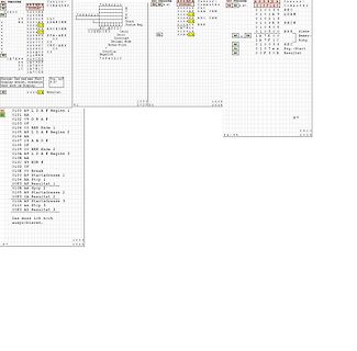
der andere Adresse 1, Ausgänge bezeichnet P10-P17. P10-P16 gehen auf D0-D7 der Anzeigen. P00-P02 gehen auf A0-A2 der 138er. P03 geht auf E1 des linken 138. P04 geht auf E1 des rechten 138. P06 geht auf E2 der 138er und WR der Anzeigen. Y7-Y4 des linken 138er geht auf die CEs der Anzeigen 1-4
PowerOn-Verzögerung und geht noch auf P07. BL0 und BL1 steuern die Helligkeit der FlächenLeds (L/L=aus). P05 liegt fest auf GND
mode (see Fig.11). Output data is transmitted to the port by the WRITE mode (see Fig.10). 1997 Apr 02 8 Philips Semiconductors Product specification 2 Remote 8-bit I/O expander for I C-bus PCF8574 D L V 7 e 2 D d e A M l a A o s D k m a f A p t I t 2 A o A V o A 1 a D T a D d e d e l v o s k m a f A v
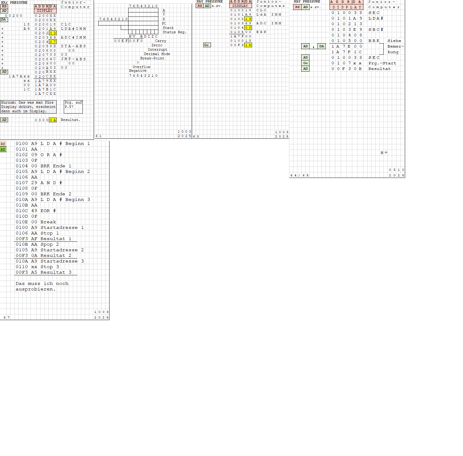
KSV PRESENTER Computer: 76543210
RS AD sv. DISPLAY
00 00 00
01 00 03 00 LDA
02 00 04 00 STA
03 00 07 00 ADC
04 00 0A 00 SBC
05 00 0D 00 BRC
06 00 10 00
07 00 13 00
08 00 16 00
09 00 19 00
0A 00 1C 00
0B 00 1F 00
0C 00 22 00
0D 00 25 00
0100 A9 L D A # Beginn 1
0101 AA
0102 09 O R A # Ende 2
0103 0F
0104 00 BRK Ende 1
0105 AA L D A # Beginn 2
0106 AA
0107 29 A N D # Ende 2
0108 AA L D A # Beginn 3
0109 AA
010A 49 E R # Ende 3
010B AA
010C 4F
010E 00 Break
0110 AA Startadresse 1
0116 AA Resultat 1
011F AA Stop
0120 AA Startadresse
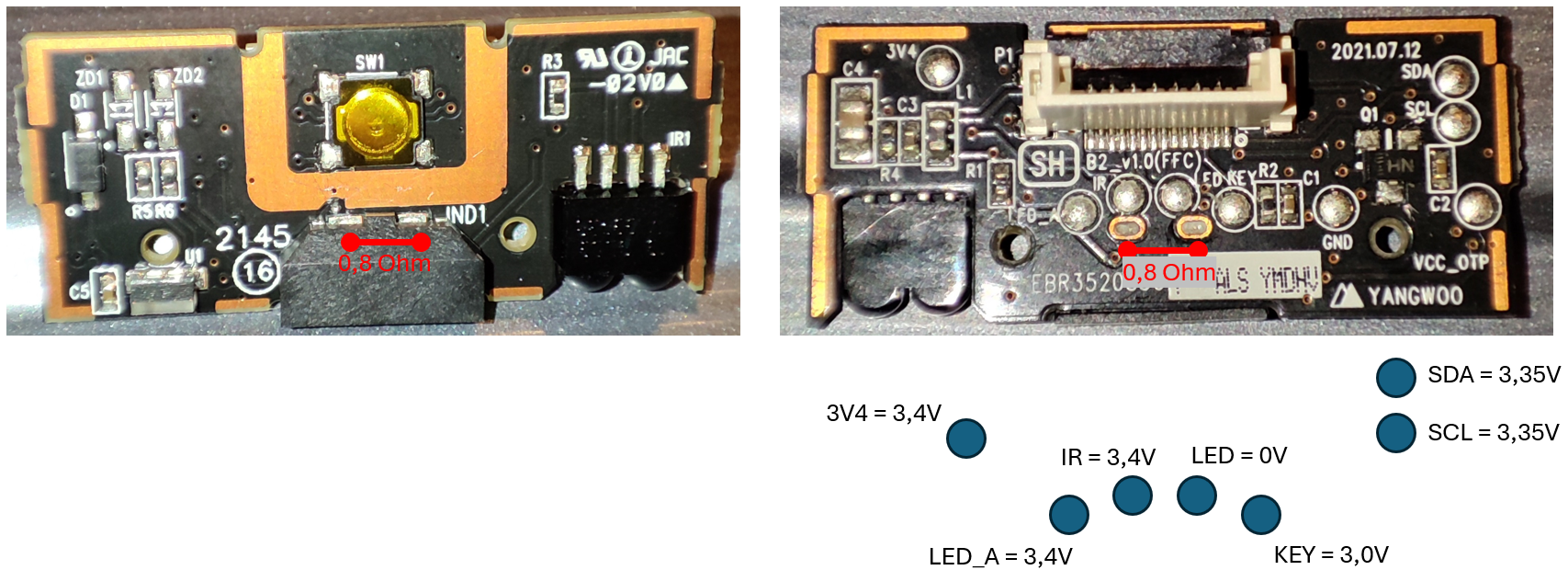
Moin Leute, Ich repariere gerade einen SMT02. Allerdings soll das Thema dieses Threads weniger der Signalgenerator selber sein, der funktioniert wahrscheinlich wieder. Sondern seine Folientastatur. Die man vermutlich auch noch bei einer Menge andere
des Multimeters auf _einen_ Kontakt geht, also sowas wie 0R erwarte, so messe ich dort meinstens O.L, also ueber 500MOhm, bewegt man sich etwas, piekst etwas, so im Bereich der Leiterbahnen, kommt man auf 10R runter. Mit anderen Worten das schwarze Zeug scheint keine richtige Leitfaehigkeit mehr zu
Hallo, Johann L. schrieb im Beitrag #7849993: > ...und hier nochmal mit einem aktuellen Compiler... Welcher genau ist das? rhf
Roland F. schrieb im Beitrag #7850013: > Johann L. schrieb im Beitrag #7849993: >> ...und hier nochmal mit einem aktuellen Compiler... > > Welcher genau ist das? v14 Wobei es die kürzeren ISR Prolog+Epilog bereits ab GCC v8 / Binutils v2.29
verwenden: 2,80€ für 3m 0,6mm mit 4,38R/m https://www.ebay.de/itm/253349283035 91cm davon haben 4,02R, macht 2,98A bei 12V entsprechend so 39W/m Für 1,1m Schneidlänge reicht das Netzteil nicht.
im Beitrag #7839733: > Und dieser Teil liegt auf N-Potential Ja, aber leider die andere Seite an L. Hoffentlich werden nicht irgendwann metallischen Führungsschienen beim schneiden verwendet... Das wären mir die gesparten 10€ für ein stärkeres Netzteil nicht wert: https://www.ebay.de/itm/326402035639
Data and Its Use” provides R qJC detailed instructions. 1 D = 0.5 E 0.5 E N T T 0.3 C S 0.2 E E 0.2 E L 0.1 E M 0.1 I E 0.05 P(pk) RqJC(t) = r(JC R A H R = 1.67°C/W MAX R T0.05 0.02 qJC O E D CURVES APPLY FOR POWER ) S0.03 t1 PULSE TRAIN SHOWN r A t READ TIME AT 1 T0.02 0.01 2 TJ(pk) C = (pk) qJCt) SINGLE PULSE DUTY CYCLE, D = 1 2t 0.01 0.01 0.02 0.05 0.1 0.2 0.5 1 2 5 10 20 50 100 200 500 1000 t, TIME (ms) Figure 9. Thermal Response http://onsemi.com 4 MTP12P10 1600 ) 0 S TJ= 25°C TC= 25°C L −2 I = 12 A V GS= 0 ( D ) 1200 f = 1 MHz E −4 p A
B E D I E N U N G S A N L E I T U N G Version 08/02 Ladeautomatik Best.-Nr.: 19 79 12 Impressum Diese Bedienungsanleitung ist eine Publikation der Conrad Electronic GmbH, Klaus-Conrad-Straße 1, D-92240 Hirschau. Alle Rechte einschließlich
unterscheiden: [c] MLPF-WL-01D3 matched in low-power mode, 16dBm, 826MHz to 958MHz, 4-layer PCB MLPF-WL-02D3 matched in high-power mode, 20dBm, 826MHz to 958MHz, 4-layer PCB MLPF-WL-04D3 matched in high-power mode, 16dBm, 413MHz to 479MHz, 4-layer PCB [/c] ### Raspberry Pi SC1820 - Uptonitischer
, dass die „Fertigstellung“ der Module Zeit in Anspruch nimmt. Wer eine Lösung auf Basis von nRF54L15 oder nRF54L05 zu realisieren gedenkt, kann bei Fanstel schlüsselfertige Module kaufen - vom Aufbau her erinnern sich stark an das, was man im Hause Espressif vorfindet. Zu beachten ist, dass es unter
Hans-Georg L. schrieb im Beitrag #7839237: > Hier geht es aber darum eine Anwendug zu debuggen das ist etwas ganz > anderes. Nö, es ging um den Compiler. Der war damals wohl halt beim DDK mit dabei.
Hans-Georg L. schrieb im Beitrag #7839237: > > Hier geht es aber darum eine Anwendug zu debuggen das ist etwas ganz > anderes. Hast du schon mal einen Treiber geschrieben und mit diesen > Tools gearbeitet
ein Wert für den Widerstand, der deutlich geringer ist. Zum Beispiel: NEOZED-Sicherung, Typ D02, Anwendungsbereich gG, 50A, 400V ac, 50 kA
Und > 330kVA sind sicher nicht auf der 400V Ebene angeschlossen. https://elektromotoren.de/KHS315L1-IP23-360KW-3450NM-1000RPM-3AC-ASYNCHRON-MOTOR Und es gibt größere.
multiple microarchitecture updates. These include a narrow fetch and decode datapath, densely banked L1 caches, a reduced-port integer register file, and other optimizations. Significant microarchitecture innovations, such as efficient branch predictors and pre-fetchers, as well as memory system improvements
gute Zusammenfassung der Informationen liefert CNX unter der URL https://www.cnx-software.com/2025/02/27/arm-cortex-a320-low-power-cpu-is-the-smallest-armv9-core-optimized-for-edge-ai-and-iot-socs/, ### Renesas: Sicherheitszertifizierung für einige MCU-Familien erreicht Die Verwendung zertifizierter
Ralf X. (ralf0815) 27.02.2025 18:22 danke, das werd ich probieren! LG Walter
Michael L. schrieb im Beitrag #7837150: > Entweder hat der TE den Wasserzulauf zufällig noch rechtzeitig gemerkt > oder es ist längestens Wasser durch die Dichtung des Einlaufschlauchs, > desser unterer Rand
DLC-4830 Blockschaltbild V1.0 26.02.2025 PZ (2) PE (1) SP (3) IV (2) DR (1) M (3) 7447 7447 hs 1—3 P14-P17 P10-P13 LEDs red (matrix) 4 ASW - P DR L DR R NRD INV ASD - - FALL HLD RISE DP ABE MCT hs 4—6 6 CH1 CH2 CH3 CH4 CH5 CH6 CH7 CH8

 Bild
Bild
 Bild
Bild
 Bild
Bild
 Bild
Bild
 Bild
Bild
 Bild
Bild
 Bild
Bild
 Bild
Bild

 Bild
Bild

 Bild
Bild