
-
PDF
2__HV9961_.pdf
include the following marks: Si or 16-Lead SOIC (NG) Thermal Resistance Package θJA O 8-Lead SOIC 128 C/W 16-Lead SOIC 82 C/W Electrical Characteristics (Specifications are aA T = 25°CINV = 12VLD= VDD PWMD = V DD unless otherwise noted)) Sym Description Min Typ Max Units Conditions Input 1 V INDC Input
in „LED-Treiber Dimensionierung“ · Analoge Elektronik und Schaltungstechnik ·
-
Datei
spiGeneric.h
interruption and reach the maximum possible SPI speed. */ size_t inQueue = 0; const size_t inQueueMax = SPIQUEUEDEPTH; //defined by hardware bool success = true; bool timeout = false; size_t txLen = len; size_t rxLen = len; //printf("Len: %u\r\n", (unsigned int)len); uint32_t timeStart = HAL_GetTick
in „STM32: SPI - HAL durch eigenen code ersetzen“ · Mikrocontroller und Digitale Elektronik ·
-
PDF
CS42L51_F3.pdf
(SD-SK) SDIN Hold Time After SCLK Rising Edge t 20 - ns h DS679F3 19 CS42L51 Parameters Symbol Min Max Units Master Mode (Note 16) Output Sample Rate (LRCK) All Speed Modes MCLK F s - - Hz (Note 17) 128 LRCK Duty Cycle 45 55 % SCLK Frequency 1/tP - 64•Fs Hz SCLK Duty Cycle 45 55 % LRCK Edge to SDOUT
in „STM32H7B3I-DK - Soundausgabe“ · Mikrocontroller und Digitale Elektronik ·
-
Datei
DC_Motor_Regler.c
define PWM_AUFLOESUNG 300 // ergibt ca. 200 Hz PWM-Frequenz #define PWM_80 (PWM_AUFLOESUNG*8/10) // max. Tastverhältnis begrenzen #define MAX_STELLWERT 5 // max. Aenderung begrenzen #define STELLWERT_TEILER 5 // max. 20% der akt. Differenz istwert-sollwert int16_t pwm_wert; // PWM-Vorgabe volatile int16
in „Drehzahlregler für DC-Motor, ATmega48-328“ · Projekte & Code ·
-
Datei
Cinni-Regler_V1-1.c
nach Nulldg. // 1 = Minimum = fast voller Sinus if (SollPhase > 25) SollPhase = 25; // Begrenzung max. vor Nulldg. // 25 = knapp über Max-Wert zum Anlaufen des Motors // (d.h. Motor läuft noch sicher _nicht_!) } if (IstPhase >= 38) PORTD &= ~(1 << PD5); // D.5=0 SSR Aus else if (IstPhase == SollPhase
in „Vorstellung Drehzahlregler mit Triac in Steckergehäuse“ · Mikrocontroller und Digitale Elektronik ·
-
Datei
main.c
runs off the 32.768 kHz ULP oscillator (20 MHz osc stays off). * PWM: TCA0 with PER = 127 -> 256 Hz, 128 levels. While the LED is off the CPU * sits in POWER-DOWN (~0.1 uA, wake on PA1 edge), while on in IDLE so the PWM * keeps running. The PIT (7.8 ms tick, CYC256 of 32.768 kHz) only runs while a * press
in „Lampe Timer deaktivieren“ · Analoge Elektronik und Schaltungstechnik ·
-
PDF
Western_Digital_FD1791.pdf
operate on a mUltiplexed bus with other bus-oriented devices. Search or Entire Track Read Selectable 128 Byte or Variable Length Record • WRITE MODE The FD1791 is fabricated in N-channel Silicon Gate MOS technology and is TTL compatible on all Single/Multiple Record Write with Automatic inputs and outputs
in „(S)uche FDC SAB 1791 02P“ · Markt ·
-
PDF
AVR-Tutorial.pdf
Schlimmstenfalls ist die Hintergrundbeleuchtung dann etwas zu dunkel. Teil 10 (Der UART) • 1 Pegelwandler MAX232, MAX232A oder MAX202 • 5 Kondensatoren • Bei einem MAX232: je 1µF Elektrolytkondensator • Bei einem MAX202 oder MAX232A: je 100nF Keramik- oder Elektrolytkondensator Die Kondensatoren dürfen auch größer sein. Ist man sich nicht sicher, welchen MAX232 man hat (Aoder nichtA), dann die größeren Kondensatoren 1µF nehmen, die funktionieren auch beim MAX232Aoder MAX202. • 1 9-polige SUBD-Buchse (female) • 1 dazu passendes Modem(nicht Nullmodem!)-Kabel
in „AVR-Tutorial als PDF“ · Offtopic ·
-
PDF
Relais_BE_Serie_D.pdf
31 Kontakt 66 Kontakt 79 Kontaktform → Form A Form A / B Form A Kontaktdaten Bedingungen Min. Typ. Max. Min. Typ. Max. Min. Typ. Max. Ein. Kombinationen von Schaltspannung und Schaltleistung Schaltstrom dürfen die angegebene ma- 50 10 25 W ximale Schaltleistung nicht übersteigen Schaltspannung DC oder
in „[V] Quecksilber-Relais - Elfein ECO 842M-2Q39-5V“ · Markt ·
-
Datei
emul-indent.c
8, 8, 1056, 544, 4, sw, bl); sihi.flags = PSize | PMinSize | PMaxSize; sihi.min_width = 1056; sihi.max_width = 1056; sihi.min_height = 544; sihi.max_height = 544; XSetStandardProperties(disp, win, " ", " ", None, 0, 0, &sihi); XSelectInput(disp, win, ExposureMask | KeyPressMask | KeyReleaseMask | ButtonPressMask
in „Befehlssatz der bo8-CPU - was ist gut, was ist schlecht“ · Offtopic ·
-
PDF
TM56E6422-tenxtechnology.pdf
18Fh.6~0 SVL: DAC output voltage select (reference source can be selected as V CC or VBG 000_0000: 0/128 * reference source 000_0001: 1/128 * reference source … 111_1101: 125/128 * reference source 111_1110: 126/128 * reference source 111_1111: 127/128 * reference source DS-TM56E6422_E 74 Rev 0.9, 2024
in „MCU identifikation/Datenblatt - MC9989A0ZQ“ · Mikrocontroller und Digitale Elektronik ·
-
PDF
AT89C51ED2.pdf
MOVX instructions, and with the EXTRAM bit cleared in the AUXR register (see Table 19). The lower 128 bytes can be accessed by either direct or indirect addressing. The Upper 128 bytes can be accessed by indirect addressing only. The Upper 128 bytes occupy the same address space as the SFR. That means
in „Einstieg in die C-Programmerung für µC“ · Mikrocontroller und Digitale Elektronik ·
-
PDF
MCP41010.pdf
(SOIC) E E1 p D 2 B n 1 h α 45° c A2 A φ β L A1 Units INCHES* MILLIMETERS Dimension Limits MIN NOM MAX MIN NOM MAX Number of Pins n 8 8 Pitch p .050 1.27 Overall Height A .053 .061 .069 1.35 1.55 1.75 Molded Package Thickness A2 .052 .056 .061 1.32 1.42 1.55 Standoff § A1 .004 .007 .010 0.10 0.18 0.25
in „Widerstand regeln“ · Mikrocontroller und Digitale Elektronik ·
-
PDF
11195c.pdf
(SOIC) E E1 p D 2 B n 1 h α 45° c A2 A φ β L A1 Units INCHES* MILLIMETERS Dimension Limits MIN NOM MAX MIN NOM MAX Number of Pins n 8 8 Pitch p .050 1.27 Overall Height A .053 .061 .069 1.35 1.55 1.75 Molded Package Thickness A2 .052 .056 .061 1.32 1.42 1.55 Standoff § A1 .004 .007 .010 0.10 0.18 0.25
in „DC-DC Wandler mit MCP42010“ · Mikrocontroller und Digitale Elektronik ·
-
PDF
mcp41xxx.pdf
(SOIC) E E1 p D 2 B n 1 h α 45° c A2 A φ β L A1 Units INCHES* MILLIMETERS Dimension Limits MIN NOM MAX MIN NOM MAX Number of Pins n 8 8 Pitch p .050 1.27 Overall Height A .053 .061 .069 1.35 1.55 1.75 Molded Package Thickness A2 .052 .056 .061 1.32 1.42 1.55 Standoff § A1 .004 .007 .010 0.10 0.18 0.25
in „Schaltregler, Feedback und Op Amp“ · Analoge Elektronik und Schaltungstechnik ·
-
PDF
89C51CC01C-SLSUM.pdf
TLHLL Min 2 T - x T - x 10 ns TAVLL Min T - x 0.5 T - x 15 ns T Min T - x 0.5 T - x 15 ns LLAX TLLIV Max 4 T - x 2 T - x 30 ns TLLPL Min T - x 0.5 T - x 10 ns TPLPH Min 3 T - x 1.5 T - x 20 ns TPLIV Max 3 T - x 1.5 T - x 40 ns TPXIX Min x x 0 ns TPXIZ Max T - x 0.5 T - x 7 ns TAVIV Max 5 T - x 2.5 T -
in „Bit Adressierung“ · Mikrocontroller und Digitale Elektronik ·
-
Datei
test7.c
117, 118, 119, 119, 120, 120, 121, 121, 122, 122, 123, 123, 124, 124, 125, 125, 126, 126, 127, 127, 128, 128, 129, 129, 130, 130, 131, 131, 132, 133, 133, 134, 134, 135, 135, 136, 136, 137, 137, 138, 138, 139, 139, 140, 140, 141, 141, 142, 142, 143, 143, 144, 144, 145, 145, 146, 146, 147, 148, 148, 149
in „Frage zu Interrupt“ · Mikrocontroller und Digitale Elektronik ·
-
PDF
CMUcam2_manual.pdf
pan and tilt reporting. In this case, since it doesn’t see the object, the servos stay at position 128: :SM 15 ACK :TC ACK T 0 0 0 0 0 0 0 0 128 128 SO servo_number level \r This command sets a Servo Output on the CMUcam to be either a constant high or low value. This essentially converts the servo outputs
-
PDF
FAT_Beschreibung.pdf
. FATX FileAllocation Table #X ( in der Regel aber nur 2) Root Verzeichnis (nur FAT12 und FAT16(B) MaxEntry⋅32Byte BytesPerSector MaxEntry → Max.Anzahl der Verzeichniseinträge, welche bei der Formatierung festgelegt werden. BytesPerSector → i.R. 512 Data Datenablage Anzahl Cluster * Sektoren je Cluster
in „Beschreibung des FAT12/FAT16 Dateisystems“ · Mikrocontroller und Digitale Elektronik ·
-
Datei
avrdude.txt
Size Size #Pages MinW MaxW ReadBack ----------- ---- ----- ----- ---- ------ ------ ---- ------ ----- ----- --------- flash 65 6 32 0 yes 8192 64 128 4500 4500 0xff 0xff Block Poll Page Polled Memory Type Mode Delay Size Indx
in „ATtiny84A-PU mit AVRISP mkII programmieren“ · Mikrocontroller und Digitale Elektronik ·
-
Datei
adc.c
samples) { uint8_t sreg; uint8_t i; sreg = SREG; cli(); adc_div[channel] = samples; for (i = 0; i < MAX_SAMPLES; i++) adc_sample_buf[channel][i] = 0; adc_lptr[channel] = 0; adc_hptr[channel] = ADC_SAMPLES(channel) & (MAX_SAMPLES - 1); adc_sum[channel] = 0; SREG=sreg; } uint16_t get_adc_value (uint8_t
in „Problem mit ADC-Routine (ATMega32)“ · Mikrocontroller und Digitale Elektronik ·
-
Datei
PID2.txt
PR2=255, Postscaler=1) //Bei 8Mhz Taktfrequenz: Inkrementierung jeweils nach 0.5us, // Überlauf nach 128us // Interrupt nach 128us. //Mit den Einstellungen von Timer2 ergibt sich eine PWM-Periodendauer // fpwm von (1/fosc)*4*Timer2_mode*(Timer2_period+1), Tcy=4*Tosc // Tpwm=(1/8MHz)*4*1*256=128us, fpwm=7.8125kHz // range=CCPR1L:CCP1CON<5:4> =DCR*4*(PR2+1)=0.94*4*256=963max bei DCR=0.94 // Pulsbreite=(CCPR1L:CCP1CON<5:4>)*Tosc*(TMR2 Prescale Value)=120.375us // Auflösung=log(4*(PR2+1))/log(2)=log(1024)/log(2)=10bits maximale Auflösung setup_adc_ports( sAN0 | sAN1 | VSS_VDD
in „PI-Regler (PIC) Problem mit Abtastzeit und Totzeit“ · Mikrocontroller und Digitale Elektronik ·
-
PDF
Katalog_2013-14__250.pdf
Stahl, gehärtet Abtriebswellenlagerung Kugellager r Option Sinterlager a Radialspiel, 10 mm ab Flansch max. 0.2 mm e Axialspiel max. 0.2 mm g Max. zulässige Axiallast 100 N n Max. zulässige Aufpresskraft 100 N o Drehsinn, Antrieb zu Abtrieb = x Empfohlene Motordrehzahl < 6000 min-1 Empfohlener Temperaturbereich
in „suche Datenblatt von einem Maxon Motor siehe Bild im Anhang“ · Mikrocontroller und Digitale Elektronik ·
-
PDF
ST_7262.pdf
enable/disable the interrupt which is generated ARR value Resolution when the OVF bit is set. Min Max 0: Overflow Interrupt disable. 1: Overflow Interrupt enable. 0 8-bit ~0.244-KHz 31.25-KHz [ 0..127 ] > 7-bit ~0.244-KHz 62.5-KHz Bit 0 = OVF Overflow Flag [ 128..191 ] > 6-bit ~0.488-KHz 125-KHz This
in „Unteschiede I²C / SPI“ · Mikrocontroller und Digitale Elektronik ·
-
PDF
memcpy_log.pdf
10 10 6.7 5 test_gcc9_3.exe 0.2 0.5 1 2 3.4 6.1 16 25.3 35.9 22.9 15.7 13.7 13.5 4.6 4.1 test_gcc9_max_1.exe 0.3 0.5 1.3 2.5 4.9 9.1 19 23.8 25.2 20.5 12.4 12.3 12.2 4.7 3.6 test_gcc9_max_2.exe 0.4 0.7 1.2 2.1 4.3 8 17.7 23 20.3 16.8 12 10.1 10 7.1 5 test_gcc9_max_3.exe 0.2 0.5 0.9 2 3.4 6.1 16.5 24.7
-
PDF
AT89S8252_Datasheet_doc0401.pdf
The AT89S8252 implements 2K bytes of on-chip EEPROM for data storage and 256 bytes of RAM. The upper 128 bytes of RAM occupy a parallel space to the Special EEPROM and RAM Function Registers. That means the upper 128 bytes have the same addresses as the SFR space but are physically separate from SFR space
in „lichtschranke mit zählfunktion einer umdrehung“ · Mikrocontroller und Digitale Elektronik ·
-
PDF
AT89S8252.pdf
The AT89S8252 implements 2K bytes of on-chip EEPROM for data storage and 256 bytes of RAM. The upper 128 bytes of RAM occupy a parallel space to the Special EEPROM and RAM Function Registers. That means the upper 128 bytes have the same addresses as the SFR space but are physically separate from SFR space
in „UART_ Werte empfangen???“ · Mikrocontroller und Digitale Elektronik ·
-
PDF
AT89S8252.pdf
The AT89S8252 implements 2K bytes of on-chip EEPROM for data storage and 256 bytes of RAM. The upper 128 bytes of RAM occupy a parallel space to the Special EEPROM and RAM Function Registers. That means the upper 128 bytes have the same addresses as the SFR space but are physically separate from SFR space
in „I2C Anschluß AT89S8252“ · Mikrocontroller und Digitale Elektronik ·
-
PDF
doc0401.pdf
The AT89S8252 implements 2K bytes of on-chip EEPROM for data storage and 256 bytes of RAM. The upper 128 bytes of RAM occupy a parallel space to the Special EEPROM and RAM Function Registers. That means the upper 128 bytes have the same addresses as the SFR space but are physically separate from SFR space
in „IDE für 8051“ · Mikrocontroller und Digitale Elektronik ·
-
PDF
DATA_Sheet_TINY_Tiger_Module_V002_en.pdf
w Max current for digital outputs: 1.6 mA / pin (low, U=0.45V max) -0.4 mA / pin (high, U=2.4V min) V002 www.wilke.de • support@wilke.de • +49 241 / 918 900 • fax: +49 241 / 918 9044 1 of 3 TM TINY-Tiger High Speed Multitasking Computers Max. darlington driver current: -3,5 mA (U=1.5V), max 8 pins n o w Rising time / falling time: 15 ns typ. (10%, 90%) i w Impedance digital Inputs: L33 ... L37nce opull-up 50 ... 150 kΩresistor: t L41 pull-up
in „geeigneter Transistor zur Schrittmotor/Treiberansteuerung über Puls/Richtungssignal mit MC“ · Analoge Elektronik und Schaltungstechnik ·
-
Datei
config.c
16000000 ADCSRA = (1<<ADEN) | (1<<ADSC) | (1<<ADIE) | (1<<ADPS2) | (1<<ADPS1) | (1<<ADPS0);///16MHz/128 = 125kHz (50-200kHz) = 125kHz #elif F_CPU == 8000000 ADCSRA = (1<<ADEN) | (1<<ADSC) | (1<<ADIE) | (1<<ADPS2) | (1<<ADPS1) | (1<<ADPS0);///8MHz/128 = 62.5kHz (50-200kHz) = 62.5kHz #elif F_CPU == 4000000
in „optimize Os / O0“ · Mikrocontroller und Digitale Elektronik ·
-
Datei
main.cpp
PLL_fuer_Landolt.cpp * * DDS Code von S.Landolt * * Created: 12.03.2021 * Author : Devil-Elec * Code angepasst für AVR128DB48 mit TCD0 und PLL * Board: AVR128DB48 Curiosity Nano * * Ausgangspin: PA5 */ // #define TIMERTAKT_PLL // für 48MHz PLL Takt "einkommentieren" #include <avr/io.h> #include <avr/pgmspace.h> void initPins
in „Attiny2313 Timer16 Bit, Normal Mode, unsauber“ · Mikrocontroller und Digitale Elektronik ·
-
PDF
lnix-s-a0001298418-1.pdf
pages and configuration screens • Interactive web pages through the use of Java applets • E-mail • 128-, 192-, or 256-bit AES Rijndael encryption (Optional) • EMI tested and compliant • Extended operating temperature: -40 to +85˚ C normal mode -40 to +75˚ C high-performance mode • High-performance processor
in „[V] 1Stück gebrauchtes XPORT-EDGE_Seriell- LAN Modul (12€)“ · Markt ·
-
PDF
lnix-s-a0001298418-1.pdf
pages and configuration screens • Interactive web pages through the use of Java applets • E-mail • 128-, 192-, or 256-bit AES Rijndael encryption (Optional) • EMI tested and compliant • Extended operating temperature: -40 to +85˚ C normal mode -40 to +75˚ C high-performance mode • High-performance processor
in „[V] 1Stück neues Lantronix_XPORT_Seriell- LAN Modul (18€)“ · Markt ·
-
Datei
main.c
len<(MAX_CREP_MSG-(sizeof(remote_ether_message_t)+1))) { if (len>size) len = size; memcpy(data,&(rem->data),len); return (len); } } } return (0); } char remote_ether_tx(char *data, word16 size) { // Format the message byte message[MAX_CREP_MSG]; remote_ether_message_t *rem = (remote_ether_message_t *) message; int nbytes; struct sockaddr_in name; if (!remote_ether_sock) return (FALSE); if (size>(MAX_CREP_MSG-sizeof(remote_ether_message_t
in „Versuche UDP-Kommunkation Beispielcode zu compilieren“ · Mikrocontroller und Digitale Elektronik ·
-
Datei
test7.c
117, 118, 119, 119, 120, 120, 121, 121, 122, 122, 123, 123, 124, 124, 125, 125, 126, 126, 127, 127, 128, 128, 129, 129, 130, 130, 131, 131, 132, 133, 133, 134, 134, 135, 135, 136, 136, 137, 137, 138, 138, 139, 139, 140, 140, 141, 141, 142, 142, 143, 143, 144, 144, 145, 145, 146, 146, 147, 148, 148, 149
in „Frage zu Interrupt“ · Mikrocontroller und Digitale Elektronik ·
-
PDF
hd61830.pdf
types of 5 × 11 dot characters Total 192 characters Can be extended to 256 characters (4 kbytes max.) with external ROM 1300 HD61830/HD61830B • Interfaces to 8-bit MPU • Display duty cycle (can be selected by a program) Static to 1/128 duty cycle • Various instruction functions Scroll, cursor on
in „ATMega als LCD-Controller“ · Mikrocontroller und Digitale Elektronik ·
-
PDF
hd61830.pdf
types of 5 × 11 dot characters Total 192 characters Can be extended to 256 characters (4 kbytes max.) with external ROM 1300 HD61830/HD61830B • Interfaces to 8-bit MPU • Display duty cycle (can be selected by a program) Static to 1/128 duty cycle • Various instruction functions Scroll, cursor on
in „HD61830A durch HD61830B ersetzen“ · Mikrocontroller und Digitale Elektronik ·
-
PDF
hd61830.pdf
types of 5 × 11 dot characters Total 192 characters Can be extended to 256 characters (4 kbytes max.) with external ROM 1300 HD61830/HD61830B • Interfaces to 8-bit MPU • Display duty cycle (can be selected by a program) Static to 1/128 duty cycle • Various instruction functions Scroll, cursor on
in „HD61830 Ansteuerung“ · Mikrocontroller und Digitale Elektronik ·
-
PDF
hd61830--kompatibel_zu_LC7981.pdf
types of 5 × 11 dot characters Total 192 characters Can be extended to 256 characters (4 kbytes max.) with external ROM 1300 HD61830/HD61830B • Interfaces to 8-bit MPU • Display duty cycle (can be selected by a program) Static to 1/128 duty cycle • Various instruction functions Scroll, cursor on
in „GLCD hängt sich nach einer Weile auf“ · Mikrocontroller und Digitale Elektronik ·
-
PDF
177932_1.pdf
characters 32 types of 5 11 dot characters Total 192 characters Can be extended to 256 characters (4 kbytes max.) with external ROM 1 HD61830/HD61830B • Interfaces to 8-bit MPU • Display duty cycle (can be selected by a program) Static to 1/128 duty cycle • Various instruction functions Scroll, cursor on/off/
in „GrafikLCD an ATmega328“ · Mikrocontroller und Digitale Elektronik ·
-
PDF
KOMMPROT.pdf
Kto: 801712-466 Kennung Länge Daten Bemerkung A 0 - PC-V sendet alle gespeicherten Trainingsdaten, max. ca. 125 kByte s. Anmerkung 1 B 0 - Trainingsspeicher Reset C 1 Intervallnr. hex auslesen der Trainingsintervalle (0..19) Daten werden in umgekehrter Reihenfolge gesendet (auch höher- und niederwertige
in „RS-232 Daten auslesen und verarbeiten“ · PC Hard- und Software ·
-
 Bild
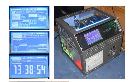
Modifizierter PC-Gehäuse mit LCD-Anzeigen
Intel(R) Celeron(R) 2.10GHz OPTION SPEED FREQUENCY 2120MHz FSB Unknown MULTIPLER 21:2 RAM PHYSICAL 128MB DRIVES C: 128MB NETWORK INFO NIC NAME Intel(R) PRO/100 UE Networ IP ADDRESSES 127.0.0.1 MAC ADDRESS 00-20-ED-JA-ED-F6 DU METER 100 Mbit MAX SPEED DATE & TIME Saturday 17 May 2003 13:38:54 HDD POWER
in „"Intelligenter" Textdisplayadapter mit Padauk PFS154“ · Projekte & Code · · Fotos
-
PDF
amd_functional_datasheet.pdf
Total Memory Sizes Per Chip Select Devices Used on DIMMs Size Per CS 64 M-bit (4M x4-bits x4 banks) 128 Mbyte 64 M-bit (2M x8-bits x4 banks) 64 Mbyte 64 M-bit (1M x16-bits x4 banks) 32 Mbyte 128 M-bit (8M x4-bits x4 banks) 256 Mbyte 128 M-bit (4M x8-bits x4 banks) 128 Mbyte 128 M-bit (2M x16-bits x4 banks
in „Am3 Mainboard Vcore instabil wenn kalt“ · PC Hard- und Software ·
-
Datei
lcdconpar.asm
zweite Hälfte der Daten behalten or temp2, temp st X+,temp2 cpi XAdresseLow, 160 ;Spalten Adresse > Max ? brne normal clr XAdresseLow ;Spalten Adresse = 0 inc ZeileL ;Zeilen Adresse ++ cpi ZeileL, 240+ZStart ;Zeilen Adresse > Max ? brne normal ldi ZeileL, ZStart ;Zeile = Beginn XRAM sbr Flags, (1<<ZeileH
in „LCD Controller für 640x480 LCD mit mega8515“ · Projekte & Code ·
-
Datei
OSZI.asm
adr_DATEN_SPEICHER = 0x0060 ;Speicher Startadresse .equ ANZAHL_DATENPUNKTE = 1000 ; ANZAHL DATENPUNKTE: max 1000 .equ ADC_RUN = 0 .equ ACDC = 1 .equ OFFSET = 2 .equ TRIGG_FL = 3 .equ TRIGGER = 4 .equ TRIGGERED = 5 .def REGSAVE = r1 .def temp = r16 .def temp2 = r17 .def tempi = r19 .def Flags = r20 .def Trigg_lev
in „einfaches DIGITAL- Oszilloskop (800 Datenpunkte) Assembler“ · Projekte & Code ·
-
Datei
U2f_pw_org_ino.ino
stdlib.h> #define BIT(x) (1<<x) #define F_CPU 16000000 // 16MHz ggf. an eff.Frequenz anpassen #define ADC_MAX 1023.0 // bei 10 Bit #define F_MIN 10.0 // bei ADC-Eingang = 0 #define F_MAX 5000.0 // bei ADC-Endanschlag #define PW_MIN 1.0e-6 // 1µs #define PW_MAX 30.0e-6 // 50µs in Sekunden #define PW_LIMIT 65500
in „spannungsgesteuerter Pulsgenerator 5-30 µs / 0-5kHz“ · Analoge Elektronik und Schaltungstechnik ·
-
PDF
siemens_cx65_cam.pdf
160 PIXEL) Data blanking 1 160 blanking subQCIF HD 1304 cycles of DCLK full/zoom 256 cycles of DCLK (128 PIXEL) blanking 1 128 blanking Data 03/06/10 14/23 TCM8210MD (A) Ver. 2.07 Exposure mode Vertical Normal mode VD 1st fra2nd fram3rd frame Data Long exp. VD mode blanking 1st frame blanking 2nd frame
in „Digitale Cmos Kamera auslesen“ · Mikrocontroller und Digitale Elektronik ·
-
PDF
M27C1001.PDF
or 5V ² 10%; V PP = VCC ) M27C1001 Unit Symbol Alt Parameter Test Condition -35 (3) -45 -60 -70 Min Max Min Max Min Max Min Max AVQV tACC Address Valid to E = VIL G = VIL 35 45 60 70 ns Output Valid tELQV CE Chip Enable Low to G = VIL 35 45 60 70 ns Output Valid GLQV OE Output Enable Low E = VIL 25 25
-
PDF
AD5241_5242-1501681.pdf
0.002 +0.01 %/% Rev. D | Page 3 of 18 AD5241/AD5242 Data Sheet 1 Parameter Symbol Conditions Min Typ Max Unit DYNAMIC CHARACTERISTICS 5, 7, 8 −3 dB Bandwidth BW_10 kΩ RAB 10 kΩ, code = 0x80 650 kHz BW_100kΩ RAB100kΩ,code=0x80 69 kHz BW_1 MΩ RAB 1 MΩ, code = 0x80 6 kHz Total Harmonic Distortion THD V =
