-
Datei
Disassambly_Listing.txt
18F0 BTFSC 0x70, 0x1 0F6 28F8 GOTO 0xf8 0F7 28F9 GOTO 0xf9 0F8 28FD GOTO 0xfd 0F9 1FF0 BTFSS 0x70, 0x7 0FA 28FC GOTO 0xfc 0FB 28FD GOTO 0xfd 0FC 2903 GOTO 0x103 585: { 586: richtung = 0; //neue Richtung
in „Falsche Quelltextposition beim Debuggen“ · Mikrocontroller und Digitale Elektronik ·
-
PDF
Option_LAN.pdf
742792038 25MHz +3.3D L21_404 C21_40 TX+ PIT21010TDP TXP PIT2101016 E-TX+ PIL210401 PIL2104P0I2CGND402 PIC210401 PIT21010TDC TXC PIT2101015 100nF TX- PIT21010TDN TXN PIT2101014 E-TX- RX+ PIT21010TDP RXP PIT2101011 E-RX+ PIT21010RDC RXC PIT2101010 RX- PIT21010RDN RXN PIT210109 E-RX- COT2101 COR2104 04 P05
in „TEKWAY DST1xx2B Oszilloskop“ · Mikrocontroller und Digitale Elektronik ·
-
Datei
RS232_Segmenttest.asm
------------------------------------------- ;-----------------------------------Belegung des PICs (PIC 16F877)------------------------- ; ; ________________ ; MCLR 5V--------1| |-------Rel 16 RB7 ; RA0 Kanalsw1------2| |-------Rel 15 RB6 ; RA1 Kanalsw2------3| |-------Rel 14 RB5 ; RA2 Kanalsw3------4
in „RS232->PIC USART“ · Mikrocontroller und Digitale Elektronik ·
-
Datei
RS232_Segmenttest.asm
------------------------------------------- ;-----------------------------------Belegung des PICs (PIC 16F877)------------------------- ; ; ________________ ; MCLR 5V--------1| |-------Rel 16 RB7 ; RA0 Kanalsw1------2| |-------Rel 15 RB6 ; RA1 Kanalsw2------3| |-------Rel 14 RB5 ; RA2 Kanalsw3------4
in „PIC nach ändern von Code undefiniertes herumwüten des uC“ · Mikrocontroller und Digitale Elektronik ·
-
Datei
16F876_LCD.ASM
INC ; ; Hardware P16F876A ; 28-pin-Testplatine ; Quarz 4MHz ; LCD 2x8 HD4470ß-kompatibel ;********************************************************************** ; ; Pinbelegung PIC16F873 76 77 ; Pin Pin ; 1 MCLR/VPP 28 RB7
in „Probleme mit LCD an PIC 16f887“ · Mikrocontroller und Digitale Elektronik ·
-
PDF
pollin_D350712D.pdf
optional) SMPS 6030-6510-0000 Programming Connector Line-In CN4-1 ) +5V-StdBy X100 P +5V-Stand-By µC, PIC16F627 CN4-2 A GND L 1W-Stand-By-Wandler CN4-3 - IRRCVR-IN 7 DISCRETE 7805 CN4-4 8IRRCVR-OUT PE LINE-FILTER CN4-5 - LED RED +24V 0 0,5VA, CN4-6 ON/OFF-KEY Kurzschlußfest +12V N Unterspannungs +5V überwachung
in „Conrac Power Supply 150W“ · Mikrocontroller und Digitale Elektronik ·
-
PDF
D350712D.pdf
optional) SMPS 6030-6510-0000 Programming Connector Line-In CN4-1 ) +5V-StdBy X100 P +5V-Stand-By µC, PIC16F627 CN4-2 A GND L 1W-Stand-By-Wandler CN4-3 - IRRCVR-IN 7 DISCRETE 7805 CN4-4 8IRRCVR-OUT PE LINE-FILTER CN4-5 - LED RED +24V 0 0,5VA, CN4-6 ON/OFF-KEY Kurzschlußfest +12V N Unterspannungs +5V überwachung
in „Laderegelung mit Schaltnetzteil“ · Mikrocontroller und Digitale Elektronik ·
-
PDF
D350712D.PDF
optional) SMPS 6030-6510-0000 Programming Connector Line-In CN4-1 ) +5V-StdBy X100 P +5V-Stand-By µC, PIC16F627 CN4-2 A GND L 1W-Stand-By-Wandler CN4-3 - IRRCVR-IN 7 DISCRETE 7805 CN4-4 8IRRCVR-OUT PE LINE-FILTER CN4-5 - LED RED +24V 0 0,5VA, CN4-6 ON/OFF-KEY Kurzschlußfest +12V N Unterspannungs +5V überwachung
in „Woran erkenne ich den Steckertryp bei einer fertigen Baugruppe“ · Mikrocontroller und Digitale Elektronik ·
-
PDF
slau213a.pdf
8 2 S D S 1S C 2 8 : d 1 S U P D 1 1 1 1 1 $ $ $ $ $ $ $ $ $ F 1 r t U P 2 3 P P P P P P P P P P P P P P 8 6 b 6 a 2 3 D 1 4 0 o 8 G u 0 1 2 3 6 F u 2 I 1R 8414 N1 5 1 . F S S S S S S S S S S SS S S1 4
in „MSP430FG4618 und der UART?“ · Mikrocontroller und Digitale Elektronik ·
-
PDF
MSP430FG4618_-_F2013_Experimenter___s_Board_-_slau213a.pdf
8 2 S D S 1S C 2 8 : d 1 S U P D 1 1 1 1 1 $ $ $ $ $ $ $ $ $ F 1 r t U P 2 3 P P P P P P P P P P P P P P 8 6 b 6 a 2 3 D 1 4 0 o 8 G u 0 1 2 3 6 F u 2 I 1R 8414 N1 5 1 . F S S S S S S S S S S SS S S1 4
in „msp430xG46x_usart1_19200.c "tested"?“ · Mikrocontroller und Digitale Elektronik ·
-
PDF
MIC5239_Data.pdf
Protection of the MIC5239 include thermal shutdown, current limit, • High-Power SOIC-8, MSOP-8, and SOT-223 overvoltage shutdown, reverse-leakage protection, Packages and reverse-battery protection. Available in the thermally enhanced SOIC-8, MSOP-8, Applications and SOT-223, the MIC5239
-
PDF
an19fc.pdf
they do not in a flyback design. Use layers = wound to just fill one layer: 2 line: L 0 782 FAC = 8.3 (fromgraph, for K = 8.95) D= B = = 0.049″ 2N ()() 9. Calculate AC winding resistance: R = (R )(F ) = (0.023)(8.3) = 0.19Ω Thenextsmalleststandardwirediameteris#18.Two AC DC AC #18 wires have three
in „LT1270 dimensionieren“ · Analoge Elektronik und Schaltungstechnik ·
-
Datei
adc1d.asm
demo1: simple running light for testing ld1...ld5 * ;* demo1: program for testing k8048/vm111 with pic16f675! * ;************************************************************************** ;* (c) velleman components,2003 all rights reserved * ;**********************************************************
in „PIC 12F675 + ADC-Eingang +Code +Dresden“ · Mikrocontroller und Digitale Elektronik ·
-
Datei
Timer_test.c
define _BRGH 0 #endif /*************************************************************************** PIC16F193X @ 8MHz ---v--- (Reset) <- RE3|1 28|RB7 -> DIP8 x <- RA0|2 27|RB6 -> DIP7 SPEED <- RA1|3 26|RB5 -> PWM1 DIP6 <- RA2|4 25|RB4 -> DIP5 DIP9 / x <- RA3|5 24|RB3 -> DIP4 DIP10 / x <- RA4|6 23|RB2 -> DIP3 x <- RA5|7 22|RB1 -> DIP2 GND <- VSS|8 21|RB0 -> DIP1 Quartz <- RA7|9 20|VDD ->+5V Quartz <- RA6|10 19|VSS -> GND x <- RC0|11 18|RC7 -> DMX RX PWM3 <- RC1|12 17|RC6 -> x PWM2 <- RC2|13 16|RC5 -> x x <- RC3|14 15|RC4 -> x ------- */ #include
in „Interrupt Zeiten - Rechenfehler gesucht..“ · Mikrocontroller und Digitale Elektronik ·
-
Datei
Kerst_elektor.asm
DB 0XF8,0X18,0X07,0X07 DB 0XF8,0X18,0X07,0X18 DB 0XF8,0X18,0X07,0X20 DB 0XF8,0X18,0X07,0X80 DB 0XF8,0X18,0X07,0X40 DB 0XF8,0X18,0X01,0XFF DB 0X18,0X00,0X7F,0X00,0X00,0X00,0X00,0X00 DB 0X18,0X00,0X80,0X1F,0X00,0X00,0X00,0X00
in „Asm Datei für Pic18F2685, mit welches Programm kompilieren?“ · Mikrocontroller und Digitale Elektronik ·
-
PDF
El_2017_0506_118-125.pdf
MCLR RC3 7 GND 3 6 RA4 RC4 2 2 RA5 RC5 5 D1 R2 8 bicolor RC6 100R RC7 9 1N4007 +5V R3 C3 PIC16F1829 k 12 RB5 RB4 13 R4 R5 C4 3 10 11 7 7 100u 50V RB7 RB6 4 4 100n 5 VSS VCC 8 R9 R6 R1 20 3 VIN+ S1 S2 SDA IC4 0 R 7 4 INA219AIDR 7 1 0 +5V 2 SCL VIN–
in „Ladezustand von Li-Ion-Akku messen“ · Mikrocontroller und Digitale Elektronik ·
-
Datei
datei-dmesg.txt
.1: reg 0x14: [io 0x0000-0x0003] [ 0.105203] pci 0000:00:1f.1: reg 0x18: [io 0x0000-0x0007] [ 0.105216] pci 0000:00:1f.1: reg 0x1c: [io 0x0000-0x0003] [ 0.105228] pci 0000:00:1f.1: reg 0x20: [io 0x1860-0x186f] [ 0.105241] pci 0000:00:1f.1: reg 0x24: [mem 0x00000000
in „Limux:: Netzwerk und WLAN futsch.“ · PC Hard- und Software ·
-
Datei
Wie_archiviert_ihr_Websites__-_Mikrocontroller.net.html
A0A0A0;padding:5px}.asm{font-family:monospace, sans-serif}.printfooter{display:none}#searchInputX{width:18ex}.sidebar #searchform{padding:0;margin:0}.urlexpansion{display:none}.editsection{font-size:0.6em}div.code table{border:1px solid #EEEEEE;background-color:#F8F8F8;table-layout:fixed;width:100%;border-collapse
-
Datei
16F876_LCD.ASM
;********************************************************************** ; Filename: 16F876 LCD_00.ASM ; Date: 14.08.2011 ; geändert ; Author: Ottmar ; Copyright free, no restriction * ;********************************************************************** ; Files: P16F876A.INC ; HD44780.INC ;********************************************************************** ; * ; Pinbelegung PIC16F873 76 77 * ; Pin Pin ; 1 MCLR/VPP 28 RB7/PGD ; 2 RA0/AN0 27 RB6/PGC ; 3 RA1/AN1 26 RB5 ; 4 RA2/AN2/VREF- 25 RB4 ; 5 RA3/AN3/VREF+ 24 RB3/PGM ; 6 RA4/T0CKI 23 RB2 ; 7 RA5/AN4/SS 22 RB1 ; 8 VSS 21
in „PIC LCD Ausgabe von Strings“ · Mikrocontroller und Digitale Elektronik ·
-
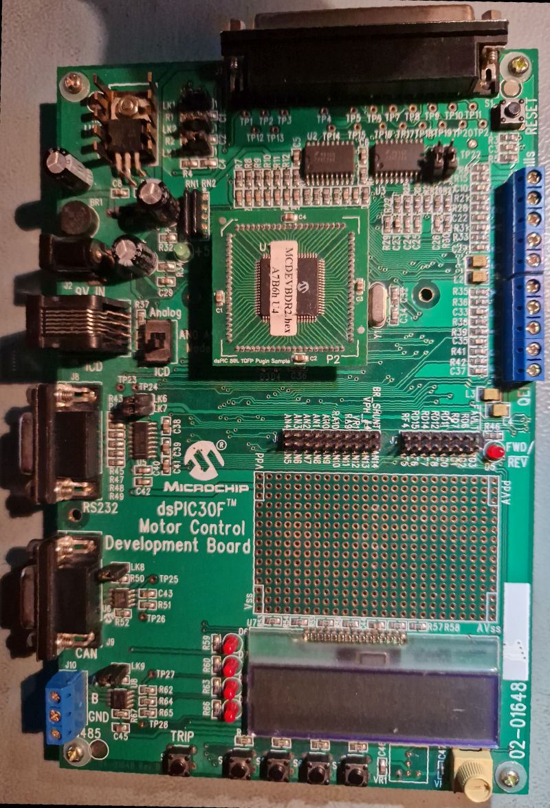
 Bild
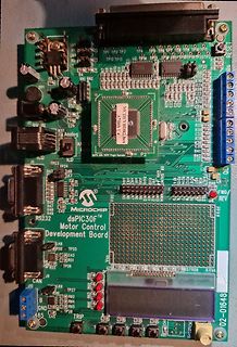
dsPIC30F Motor Control Development Board
MC9DEVBR2.14 A7B6h L4 TP1 TP2 TP3 TP4 TP5 TP6 TP7 TP8 TP9 TP10 TP11 TP12 TP13 TP14 TP15 R1 R2 R3 R4 R5 R6 R7 R8 R9 R10 R11 R12 R13 R14 R15 R16 R17 R18 R19 R20 R21 R22 R23 R24 R25 R26 R27 R28 R29 R30 R31 R32 R33 R34 R35 R36 R37 R38 R39 R40 R41 R42 R43 R44
in „[V] ältere Demoboards PIC, NEC und Motor“ · Markt · · Platinenfotos
-
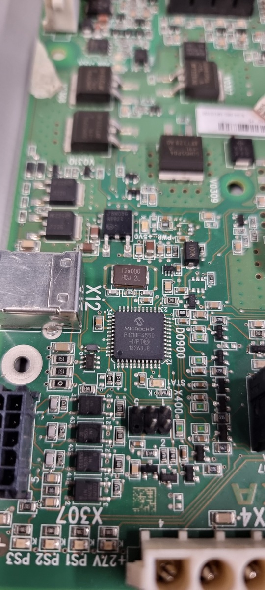
 Bild
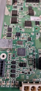
Nahaufnahme einer bestückten Leiterplatte
12s000 HCJ 2L MICROCHIP PIC18F550 -/P1E 13263J8 X12 X307 X400 D0900 V0310 V0309 PWR-5V0 PS2 PS1 +27V X4-
in „PIC18F4550 führt ständig RESET aus.“ · Mikrocontroller und Digitale Elektronik · · Platinenfotos
-
Datei
Decodierer.c
// Include Files #include <18f452.h> //Pre-Processor Funktionen #fuses HS,NOWDT,NOPROTECT,NOPUT,NOBROWNOUT, NOLVP //Sicherungen einstellen #use delay(clock=20000000) //Quarztakt des PIC einstellen #use rs232(baud=1200, xmit=PIN_C6
in „Hex-String einlesen und Binärwert laut Codetabelle zuweisen“ · Mikrocontroller und Digitale Elektronik ·
-
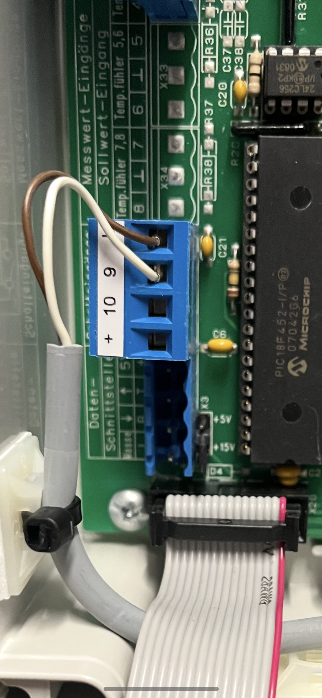
 Bild
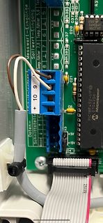
Nahaufnahme einer Leiterplatte mit Mikrocontroller und Anschlussklemmen
Messwert-Eingänge Sollwert-Eingang Temp.fühler 5,6 Temp.fühler 7,8 L 7 L 5 X33 X34 HR36 HR37 HR38 R20 C20 C21 C6 K3 + 10 9 Daten-Schnittstelle PIC18F452-I/P 07042G6 MICROCHIP +5V +15V D4
in „Was ist das für ein Stecker?“ · Platinen · · Platinenfotos
-
Datei
diskio.h
MMC_GET_SDSTAT 14 /* Get SD status */ /* ATA/CF specific ioctl command */ #define ATA_GET_REV 20 /* Get F/W revision */ #define ATA_GET_MODEL 21 /* Get model name */ #define ATA_GET_SN 22 /* Get serial number */ /*-------------------------------------*/ /* PIC18 SPI definitions and functions */ /* Note:
in „Problem mit VS1053“ · Mikrocontroller und Digitale Elektronik ·
-
PDF
AN1325_Metall_Over_Cap.pdf
implementation information, refer to the capacitor choice is actually the paired combination of a 1nF capacitor in parallel with a 0.1 µF capacitor. All next section on the system firmware. capacitors have a series resonant characteristic, which In a typical application, one or both of the above is a
in „Tastenverriegelung (Tastensperre)“ · Mikrocontroller und Digitale Elektronik ·
-
Datei
display_44780.c
/* * File: display_44780.c * Author: *** * * Created on 28. August 2014, 09:14 * * Controller: PIC18F65J50 * Compiler: XC8 v1.32 * * Function: Source-Datei für paralleles Display */ /*___Include-Files____________________________________________________________*/ #include "..\Include\config_StrgPrint.h
in „LCD "PWB16202" an PIC18F65J50“ · Mikrocontroller und Digitale Elektronik ·
-
Datei
mca25.c
0x63,0x61,0x6D,0x65, 0x72,0x61,0x2D,0x73,0x65,0x74,0x74,0x69,0x6E,0x67,0x73,0x20,0x76,0x65,0x72,0x73,0x69,0x8C,0xF9, 0xF9,0x81,0xEF,0x3F,0x6F,0x6E,0x3D,0x22,0x31,0x2E,0x30,0x22,0x20,0x77,0x68,0x69,0x74,0x65, 0x2D,0x62,0x61,0x6C,0x61,0x6E,0x63,0x65,0x3D, 0x22,0x4F,0x46,0x46,0x22, 0x20,0x63,0x6F,0x8C,0xF9, 0xF9,0x81,0xEF
in „AVR für wenig Geld im LAN“ · Mikrocontroller und Digitale Elektronik ·
-
Datei
NEW_MAP.txt
// FIRMWARE REPLACEMENT FOR CHATPAD's pic16f883 // see attached documents to learn more // release 0.3.1 from jean : giancarlotodone at yahoo dot it // for the Open Keyboard Project // thanks alot to Gidi (who owns an half of my chatpad, call
in „Chatpad PIC16F883“ · Mikrocontroller und Digitale Elektronik ·
-
Datei
main.c
/** I N C L U D E S **********************************************************/ #include <p18f4580.h> #include <delays.h> // für die Warteschleife #include <usart.h> #include <adc.h> #include <stdio.h> #include <timers.h> #pragma config OSC = HS //HS Oscillator #pragma config FCMENB = OFF //Fail-safe
in „Deklaration von Zahlen und Wo im C Programm“ · Mikrocontroller und Digitale Elektronik ·
-
PDF
LT1677.pdf
I T U U E F 25 O 15 F N PACKAGE T T O 4 E 20 E I C R 10 G E 15 P N P H 2 10 5 C 5 0 0 0 1 2 3 4 5 –1.0 –0.6 –0.2 0.2 0.6 1.0 1.4 –0.8 –0.4 0 0.4 0.8 1.2 1.6 2.0 TIME (MINUTES) INPUT OFFSET VOLTAGE DRIFT (µV/°C)
in „LT1677, Output Voltage Swing“ · Analoge Elektronik und Schaltungstechnik ·
-
PDF
LT1677fa.pdf
I T U U E F 25 O 15 F N PACKAGE T T O 4 E 20 E I C R 10 G E 15 P N P H 2 10 5 C 5 0 0 0 1 2 3 4 5 –1.0 –0.6 –0.2 0.2 0.6 1.0 1.4 –0.8 –0.4 0 0.4 0.8 1.2 1.6 2.0 TIME (MINUTES) INPUT OFFSET VOLTAGE DRIFT (µV/°C)
in „Nachbau TC1 Seismometer“ · Analoge Elektronik und Schaltungstechnik ·
-
Datei
sd.c
#include "sd.h" #include "pic18f4520.h" #include "pins.h" /*------------------------------------------------------------------------------------------------- Funktionsname: void port_init() Uebergabeparameter: keine Beschreibung
in „Mit PIC18F452 SD-Karte initialisieren“ · Mikrocontroller und Digitale Elektronik ·
-
Datei
WALTHER.ASM
output ;6 GP1 Input, High V feedback ;7 GP0 Output, low, Pulse to fire FET ;8 Ground ;TMR0 used for firing pulse period ;TMR1 used for half second timing loop for flashing LED ;TMR2 used for PWM LIST P=12F683 __config 38C4 ERRORLEVEL -302 ;stop TRIS warning message TMR0 EQU H'
-
PDF
RXV667.pdf
35 Connection F2 F2 NPNP P1 P2 P3 P4 P5 P6 P7 P8 P9P10P11P12P13P14P15P16P17P18P19P20P21P22P23P24P25P26P27P28P29P30P31 PinNo. 34 33 32 31 30 29 28 27 26 25 24 23 22 21 20 19 18 17 16 15 14 13 12 11 10 9 8 7 6 5 4 3 2
in „Yamaha RX-V667 Reparatur und Bezugsquellen?“ · Analoge Elektronik und Schaltungstechnik ·
-
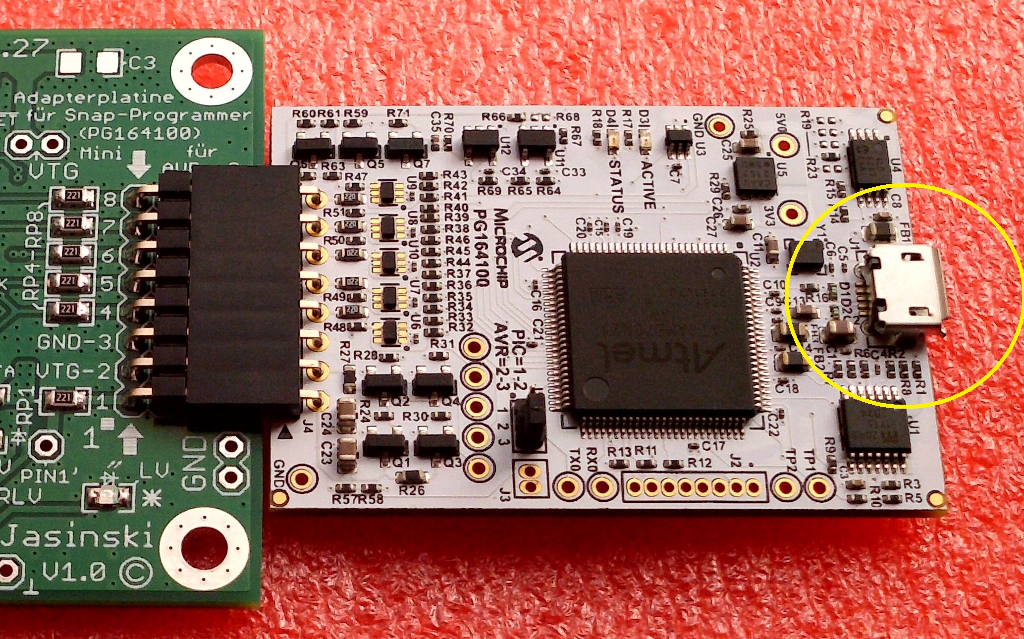
 Bild
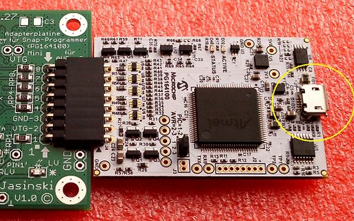
Bestückte Leiterplatte mit Atmel Mikrocontroller und USB-Anschluss
Adapterplatine für Snap-Programmer (PG164100) Mini für Atmel AVR PIC=1.2 T2.3 STATUS ACTIVE GND LV. GND U.V. Jasinski v1.0 R60 R61 R59 R74 R66 CC R68 D18 R19 R23 R43 R42 R65 R64 R67 U3 R28 R27 C26 C25 333 C8 F81 R50 R39 R48 R49 R47 R38 R37 R36 R35 R34 R33 R32 R31 R29
in „Entwurf USB-UART-Converter, KiCad, bitte um Review“ · Platinen · · Platinenfotos
-
PDF
pITX-SP_M02.pdf
...................................................................................................18 6.8 Display Default Settings .........................................................................................................18 7 USB Interface ..............................................
in „PAL / LVDS Konverter“ · Mikrocontroller und Digitale Elektronik ·
-
PDF
MSP-EXP430G2_LaunchPad.pdf
O SK S E T T U EU T E 1 A 5 U T DP N 3 T S 2 1 0 B 4 S 3 3 1 F C W S S 1 0 3 C C L A V n 2 F I 8 7 6 5 1 G G D V E E R 0 1 N N ND C CS S TT C C ST D D U n 2 1 D8 1 C1 0 RS P DR S M P R G N 2 1 84 23 2 22 2 11 1 1 7 65 D 0 C 8 8 5 4 31 0 65 4 3 E n 2 Z R V G 3 C
in „gutes Übersetzungsprogramm für Datenblätter gesucht“ · Offtopic ·
-
 Bild
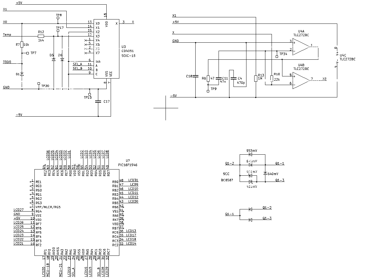
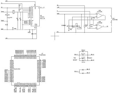
Schaltplan mit Operationsverstärkern und Mikrocontroller-Anschlüssen
X1, +5V, TP8, X0, R12, Temp, 2k4, X2, X3, X, U3 CD4051 SOIC-16, VDD, VEE, -5V, X5, X6, X7, SEL A, SEL B, Inh, A, B, C, D1, TODO, TP7, TP20, GND, TP15, C17, U4A TLC272BC, TP34, U4C TLC272BC, X0, R16, 22k, U4B TLC272BC, C18, R6, C11, 47n, C14, 470p, TP9, U7 PIC16F1946, LCD27 bis LCD14, VPP/MCLR/RG5, VSS, +5V, LCD26, LCD25, LCD24, LCD23, LCD22, LCD21, RF1 bis RF7, MCLR/RA5, RB0 bis RB7, VDD, VSS, RA0 bis RA7, RC0 bis RC7
in „Ersa RDS 80 - Defekte Bauteile (Schaltplan benötigt)“ · Mikrocontroller und Digitale Elektronik · · Schaltpläne
-
Datei
gLCD.c
*********************************** * FileName: GenProcs.c * Dependencies: GenProcs.h * Processor: PIC18F4685 * Complier: Microchip C18 * * * Author Date Comment *~~~~~~~~~~~~~~~~~~~~~~~~~~~~~~~~~~~~~~~~~~~~~~~~~~~~~~~~~~~~~~~~~~~~ * Stephan Krause 17/8/12 Version 1.0 - Initial Release **************
in „Berechnung der Übergabeparameter beim Funktionsaufruf klappt nich immer“ · Mikrocontroller und Digitale Elektronik ·
-
Datei
vwcdc.c
,'8',0,'9',0,'A',0,'B',0,'C',0,'D',0,'E',0,'F',0}; const uint8_t sVERSION[] PROGMEM = {VER_MAJOR,'.',VER_MINOR, VER_PATCHLEVEL,0}; uint8_t sendreg; uint8_t sendbitcount; // Used in SendByte routine uint8
in „CD Wechsler Protokoll“ · Mikrocontroller und Digitale Elektronik ·
-
PDF
ADV476KN50E.pdf
3IREF, RL= 37.5 , C = 30 pF, I = 8.88 mA. L REF DYNAMIC PERFORMANCE 3, 4 Clock and Data Feedthrough –35 dB typ Glitch Impulse3, 4 75 pV secs typ NOTES 1Temperature rangMINto TMAX; 0 to +70°C. 2Relative to the midpoint of the distribution
in „AVR mit mehr als 64kB sram“ · Mikrocontroller und Digitale Elektronik ·
-
Datei
tft_data.c
, 0xf9, 0x7b, 0x3, 0x3d, 0xb0, 0x38, 0xe2, 0x33, 0xa5, 0x4d, 0x2b, 0xbb, 0xd8, 0x24, 0x18, 0x70, 0x49, 0x69, 0x6a, 0xe5, 0xa5, 0x7f, 0x8e, 0x23, 0x8e, 0xbd, 0xf, 0x75, 0x89, 0x6d, 0xed, 0xdd, 0x75, 0xa7, 0x3b, 0xf0, 0x7a, 0xc8, 0x75, 0xc4, 0x7, 0xa, 0x54, 0xe3, 0x84, 0x97, 0x1b
-
PDF
MCP73837.pdf
PROG1 Typical Applications MCP73837 Typical Application Ac-dc Adapter 1 10 VAC VBAT Thermsitor 4.7 µF Single USB Port 2 V THERM 9 Li-Ion 4.7 µF USB Cell 1 kΩ 4.7 µF 3 V 5 STAT1 SS 1 kΩ 4 7 STAT2 PROG2 LowHi 1 kΩ 8 PG PROG1 6 R PROG MCP73838 Typical Application 1 10 Ac-dc Adapter VAC VBAT Thermsitor 4.7 µF 2 9 USB Port V USB THERM Cell 4.7 µF 4.7 µF 1KΩ 3 8 STAT1 TE Hi Low 1KΩ 4 STAT2 PROG2 7 Hi Low 5 6 V SS PROG1 RPROG DS22071A-page 2 © 2007 Microchip Technology Inc. MCP73837/8 Functional Block Diagram
in „Verständnissfrage - MCP73837“ · Mikrocontroller und Digitale Elektronik ·
-
PDF
39662c.pdf
3.3V ENC28J60 RJ-45 MCU TPOUT + 1 Ferr(1,3) 1 I/O CS 49.9Ω, 1% Bead SCK SCK 2 SDO SI 49.9, 1% 0.1 μF3) SDI SO TPOUT - 1:1 CT 3 Level TPIN + 4 49.9Ω, 1% Shi(2) Logic 5 49.9Ω, 1% 0.1 μF INT0 INT 1:1 CT 6 TPIN- RBIAS 7 VCAP LEDA LEDB 8 10 μF 2.32 kΩ, 1% 75Ω (375Ω(375Ω(375Ω(3) (3) 1 nF, 2 kV Note 1: Ferrite
in „Webserver mit XC167“ · Mikrocontroller und Digitale Elektronik ·
-
Datei
Petra-M10_Einblick_offen.html
#3079ed}.kpgrb{background-color:#f5f5f5;background-image:-webkit-linear-gradient(top,#f5f5f5,#f1f1f1);border:1px solid #dcdcdc;color:#555}.ksb{background-color:#f8f8f8;background-image:-webkit-linear-gradient(top,#f8f8f8,#f1f1f1);border
in „Lampentaster gesucht“ · Markt ·
-
Datei
display_44780.h
/* * File: display_44780.h * Author: *** * * Created on 28. August 2014, 09:00 * * Controller: PIC18F65J50 * Compiler: XC8 v1.32 * * Function: Konfigurationsdatei für LCD mit 44780-Treiber */ //Display-Pins -->folgende Defines in config...h auskommentieren!! #define LCD_EN PORTEbits.RE5 #define LCD_RW
in „LCD "PWB16202" an PIC18F65J50“ · Mikrocontroller und Digitale Elektronik ·
-
PDF
Hauptplatine.pdf
PA11 PIU1033USBDP PISW0OUT06 GND VCC VSS_3 PA12 PIU1034 PISW0OUT07 PIU101 PA13 PIU1037 PISW0OUT08 C8C 82 VBAT PA14 38 SPI1_SS 9 100n81 PA15 PIU1038 P2 P10W0OUT0VCC B 18 S2 R1R1 PISW0OUT010 GND B PB0 PIU1918 10k SW_OUTUT C9 GND 5 PB1 PIU2019 P0 1 ADC12_IN0N 22pIC90110C9PIU1PD0-OSC_IN PB2 PIU3920SPI1_
in „LDO wird warm, produziert zu wenig Ausgangsspannung“ · Analoge Elektronik und Schaltungstechnik ·
-
PDF
2021-06-08_apply_cwimmer_Ilume.pdf
Claus Wimmer Wilhelmstraße 52 e-f, App. 456 65183 Wiesbaden Handy: 0176 386 099 87 E-Mail: claus.erhard.werner.wimmer@gmail.com Ilume Informatik AG - Herr Anh Tu Lam - Holzhofstraße 3 55116 Mainz Wiesbaden, den 8.6.2021 Bewerbung als
in „Konntet ihr bei eurem Abschlussarbeits-Unternehmen anfangen?“ · Ausbildung, Studium & Beruf ·
-
PDF
A4964_AN_R2.pdf
values. Config[13] is: 006 Config[14] is: 070 Config[15] is: 3C2 Config[16] is: 038 Config[17] is: 04F Config[18] is: 085 Config[19] is: 021 Config[20] is: 1EF Config[21] is: 007 Config[22] is: 086 Config[23] is: 00F Config[24] is: 0FE Config[25] is: 289 Config[26] is: 001 Config[27] is: 001 Config[28
in „Allegro A4964 Demoboard - ein Phantom?“ · Analoge Elektronik und Schaltungstechnik ·
-
PDF
SAMA5D2_PTC_Firmware_UG.pdf
Name Field Bits Access Register 0x0846 raw_position 7:0 R - - - - - - - - © 0 0x0847 15:8 R - - - - - - - - 7 c 0x0848 position 7:0 R - c p 0x0849 15:8 R e h 0x084A contact_size 7:0 R l 0x084B 15:8 R - y n . P T C S u b s y s e D m S 0 F 2 r 0 m - w a a e r 8 e Table 4-4. Frequency Hopping
in „Was ist bzw. war Atmel QTouch?“ · Mikrocontroller und Digitale Elektronik ·