-
Datei
Ethernet.c
Enable SYSCFG clock */ RCC_APB2PeriphClockCmd(RCC_APB2Periph_SYSCFG, ENABLE); /* Configure MCO (PA8) */ GPIO_InitStructure.GPIO_Pin = GPIO_Pin_8; GPIO_InitStructure.GPIO_Speed = GPIO_Speed_100MHz; GPIO_InitStructure.GPIO_Mode = GPIO_Mode_AF; GPIO_InitStructure.GPIO_OType = GPIO_OType_PP; GPIO_InitStructure.GPIO_PuPd
in „STM32F207 + KS8721 (Ethernet Phy)“ · Mikrocontroller und Digitale Elektronik ·
-
Datei
usart_nrf3.h
InformAlarmDataNO; typedef union { struct { //dong 20200520 u16 WCode; u8 Alarm_Id[6] ; u8 WNum[2]; u8 WTime1[4]; u8 WTime2[4]; u8 Data1[2]; u8 Data2[2]; } Data; u8 DataMsg[22]; } AlarmDataType; typedef struct { u8 Alarm_Id[6] ; //dong 20200520 u16 WCode; u8 WNum[2]; u8 WTime1
in „Wechselrichter Hoymiles HM-xxxx 2,4 GhZ Nordic Protokoll?“ · Mikrocontroller und Digitale Elektronik ·
-
Datei
tools.c
-------- */ uint16_t changes = 0; uint32_t cells = 0; // 2 Spielfelder alt+neu struct feld_t { uint8_t last[MAX_X+1][MAX_Y+1]; uint8_t next[MAX_X+1][MAX_Y+1]; } feld; /* Die Abbildung der Matrix auf das Display */ uint8_t matrix[MAX_X+1][MAX_Y+1]; /* Datenmatrix für alle 12 Module Es werden nacheinander
in „STM32F1xx: Wie GOL am "Leben" halten?“ · Mikrocontroller und Digitale Elektronik ·
-
PDF
spwf01.pdf
actual peak temperatureP(T ) 10-20 sec Ramp-down rate 6 °C/sec Time from 25 °C to peak temperature 8 minutes max. Figure 2. Soldering profile AM17477v1 8/16 DocID025635 Rev 2 SPWF01SA, SPWF01SC Regulatory compliance 7 Regulatory compliance RF compliance The RF certifications obtained are described in
in „Wlan2Serial Modul für 5 euro“ · Mikrocontroller und Digitale Elektronik ·
-
Datei
mmc_stm32f1.c
= SPI_CR1_DFF; /* SPI wieder einschalten */ SPI_Cmd(SPI1, ENABLE); } /* --------- Wechselt auf den 8 Bit Mode ---------- */ void SPI_8Bit() { /* SPI abschalten */ SPI_Cmd(SPI1, DISABLE); /* 16 Bit auf 8 Bit setzen */ SPI1->CR1 &= ~SPI_CR1_DFF; /* SPI wieder einschalten */ SPI_Cmd(SPI1, ENABLE); } /*
in „STM32Fxxx: Frage zur Initialisierung mit der StdPeriphLib“ · Mikrocontroller und Digitale Elektronik ·
-
Datei
mmc_stm32f1.c
= SPI_CR1_DFF; /* SPI wieder einschalten */ SPI_Cmd(SPI1, ENABLE); } /* --------- Wechselt auf den 8 Bit Mode ---------- */ void SPI_8Bit() { /* SPI abschalten */ SPI_Cmd(SPI1, DISABLE); /* 16 Bit auf 8 Bit setzen */ SPI1->CR1 &= ~SPI_CR1_DFF; /* SPI wieder einschalten */ SPI_Cmd(SPI1, ENABLE); } /*
in „STM32F103: Problem mit ChanFat und SD karte“ · Mikrocontroller und Digitale Elektronik ·
-
Datei
controller.c
#include "stm32f10x_conf.h" #include <stm32f10x_lib.h> ErrorStatus HSEStartUpStatus; void RCC_Configuration(void); //Configures Clock for all devices and GPIOs void NVIC_Configuration(void); void GPIO_init(void);
in „STMF32, SPI, Master, Vollduplex“ · Mikrocontroller und Digitale Elektronik ·
-
Datei
STM32F4_lcd.c
// Anschluß einer LC-Anzeige 2x16 an das STM32F4-Discovery-Board // lcd_init() muss als erste Funktion aufgerufen werden. Danach sollten // lcd_cmd() und lcd_zeichen() Befehle und Daten korrekt ausgeben. /* Das LCD-Modul wird im 4-Bit Modus betrieben
in „LCD-Modul 2x16 am STM32F4Discovery-Board“ · Projekte & Code ·
-
Datei
spi_oled.c
#include "STM32F4xx.h" #include "_mcpr_stm32f407.h" #include "spi_oled.h" #include "tools.h" #include "timer.h" void spiInit(void) { //CONFIGURE I/Os FOR SPI2 //SCLK = PB13 setOutputPort(B, 13, ALTERNATIVE, PUSHPULL
in „0,96 Oled mit STM32F407“ · Mikrocontroller und Digitale Elektronik ·
-
 Bild
Bild
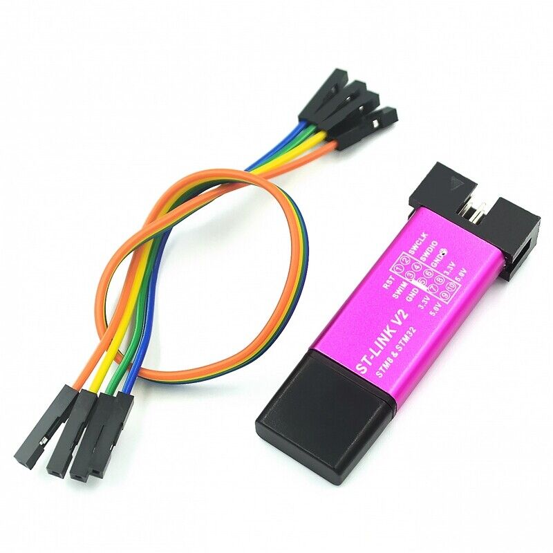
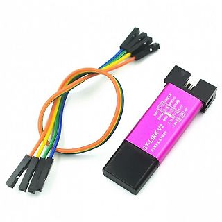
ST-LINK V2 Debugger mit Anschlusskabel
ST-LINK V2 STM8 & STM32 RST SWCLK SWDIO GND 3.3V SWIM GND 3.3V 5V 5V
in „NRF51 firmware flash mit ST-Link und openocd“ · Mikrocontroller und Digitale Elektronik · · Fotos
-
 Bild
Bild
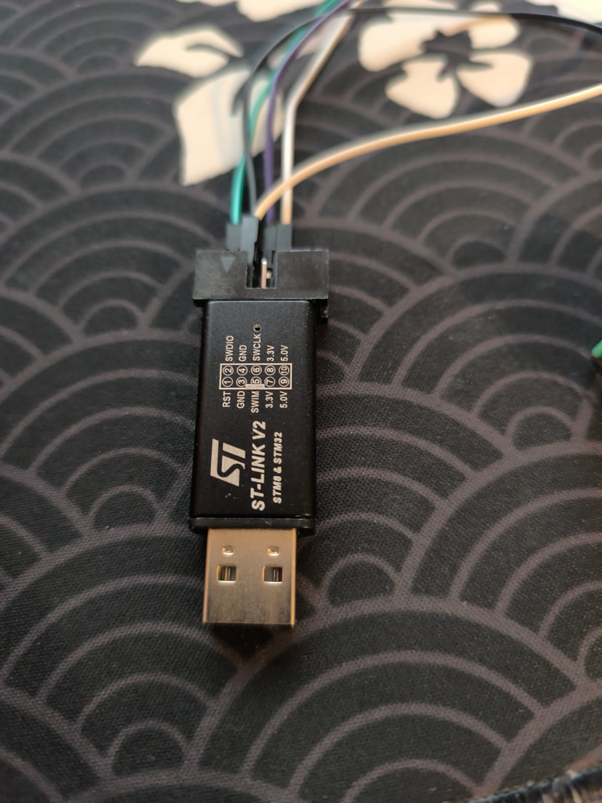
ST-LINK V2 Debugger mit Jumper-Kabeln
ST ST-LINK V2 STM8 & STM32 RST 1 GND 2 SWDIO 3 GND 4 SWIM 5 3.3V 6 5.0V 7
in „STM32F103C6T6A Lässt sich nicht programmieren“ · Mikrocontroller und Digitale Elektronik · · Fotos

-
Datei
fehlercode.txt
Failed to init device. stm32flash 0.4 http://stm32flash.googlecode.com/ Using Parser : Raw BINARY Interface serial_w32: 115200 8E1
in „USB to TTL mit CH340“ · Mikrocontroller und Digitale Elektronik ·
-
Datei
fehlercode.txt
Failed to init device. stm32flash 0.4 http://stm32flash.googlecode.com/ Using Parser : Raw BINARY Interface serial_w32: 115200 8E1
in „USB to TTL mit CH340“ · Mikrocontroller und Digitale Elektronik ·
-
 Bild
Bild
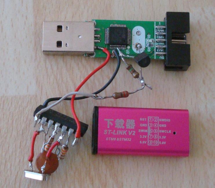
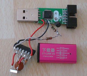
ST-LINK V2 Programmiergerät mit USB-Adapter und Verkabelung
ST-LINK V2 STM8 & STM32 RST SWDIO GND GND SWIM SWCLK 3.3V 3.3V 5.0V 5.0V 下载器
in „Quick&dirty - schnelle Problemlösungen selbst gebaut“ · Projekte & Code · · Fotos
-
Datei
STM32F7_discovery_clock.ino
/* * !!! use STM32GENERIC framework !!! from https://github.com/Bodmer/TFT_ILI9341/tree/master/examples/TFT_Clock reworked for ARDUINO DUE using the Adafruit Libraries Hardware: STM32F7 Discovery libraries used: https
in „STM32F746 Discovery ARDUINO“ · Mikrocontroller und Digitale Elektronik ·
-
Datei
main.c
#include "stm32f10x_conf.h" #include "stm32f10x_gpio.h" #include "stm32f10x_rcc.h" #define TFT_RS_PIN GPIO_Pin_10 #define TFT_RS_GPIO_PORT GPIOB #define TFT_RS_GPIO_CLK RCC_APB2Periph_GPIOB #define TFT_RS_HIGH()
in „STM32 + SSD1289“ · Mikrocontroller und Digitale Elektronik ·
-
Datei
main.c
#include "stm32f10x_conf.h" #include "stm32f10x_gpio.h" #include "stm32f10x_rcc.h" #define TFT_RS_PIN GPIO_Pin_10 #define TFT_RS_GPIO_PORT GPIOB #define TFT_RS_GPIO_CLK RCC_APB2Periph_GPIOB #define TFT_RS_HIGH()
in „STM32 + SSD1289“ · Mikrocontroller und Digitale Elektronik ·
-
PDF
MemoryMapping.pdf
Memory mapping STM32L151xx, STM32L152xx 5 Memory mapping The memory map is shown in the following figure. Figure 9. Memory map APB memory space 0xFFFF FFFF reserved 0xE010 0000 reserved 0x6000 0000 reserved 0x4002 6400
in „Pointer auf Hardwareadresse in Mikrocontroller“ · Mikrocontroller und Digitale Elektronik ·
-
Datei
main.c
#include "stm32f4xx.h" ///* Clock Ports */// void StartClock() { RCC_AHB1PeriphClockCmd(RCC_AHB1Periph_GPIOD | RCC_AHB1Periph_GPIOA | RCC_AHB1Periph_GPIOC, ENABLE); } ///* Port Configuration */// void PortConfig(
in „Datenerfassung, Analog -> USB / RS232“ · Mikrocontroller und Digitale Elektronik ·
-
Datei
i2c_init.c
============================================================ */ // write void i2c_writeOneByte(uint8_t address, uint8_t byte) { i2c_dataBytes[0] = byte; i2c_readwriteBytes(address, I2C_Direction_Transmitter, 1); } // read void i2c_readTwoBytes(uint8_t address) { i2c_readwriteBytes(address, I2C_Direction_Receiver, 2); } // start void i2c_readwriteBytes(uint8_t address, uint8_t direction, uint8_t byteCnt) { deviceAddress = address; i2cSendDirection = direction; i2cBusyFlag = 1; i2cByteCounter = byteCnt; I2C_GenerateSTART(I2C1, ENABLE); while(I2C_GetFlagStatus
in „Dataflash vom bq20z65-r1 mit I2C auslesen“ · Mikrocontroller und Digitale Elektronik ·
-
Datei
main.c
--------------------------------------------------------------*/ #include "main.h" /** @addtogroup STM32F3_Discovery_Peripheral_Examples * @{ */ /** @addtogroup ADC_Example * @{ */ /* Private typedef -----------------------------------------------------------*/ /* Private define ---------------------
in „ADC mit STM32 F3 Discovery“ · Mikrocontroller und Digitale Elektronik ·
-
Datei
config.h
stdbool.h> #include <stdint.h> /* --------------- Special Include Files / Librarys ------ */ #include "tm_stm32f4_bmp180.h" #include "tm_stm32f4_rtc.h" /* -------------- Projekt Include Files ---------------- */ /* -------------- Defintionen ---------------------------- */ // Typdefinition diverser RAM Typen
in „Organisation der Header und Includes“ · Mikrocontroller und Digitale Elektronik ·
-
 Bild
Bild
Präsentation über STM32 AI Model Zoo
Whether you are a specialist or just getting started, STM32 AI Model Zoo promises great value. Find the right model. Build your application faster. YOLOv8. Computer vision. Audio processing. Data analysis. Sensing. DATA. MODEL. Training & finetuning. Quantization. Evaluation & prediction. Compilation & benchmark. Deployment on boards. STM32 Summit. Focus on creating features that differentiate your products
in „STM32 Summit - 18nm-STM32, STM32WL3R, STM32-AI-Assistent und Erweiterungen des Ökosystems“ · Mikrocontroller und Digitale Elektronik · · Screenshots

-
Datei
MyFunctions.c
Geraet: ******************************************************************************/ #include <stm32f10x_conf.h> #include "MyFunctions.h" #include "EXTI_HW_Init.h" #include <stm32f10x_spi.h> #include <stdio.h> #include "stm32f10x_usart.h" // globale Variablen // statische Variablen uint8_t s_Rx =0,s_Tx =0; uint8_t s_Rx_control =2,s_Tx_control =2,s_Tx_check =0,s_Rx_check =0; uint8_t s_stop =0; uint8_t s_count =0; char s_RT; char s_C8; // Macros /****************************************************************
in „UART Problem beim senden“ · Mikrocontroller und Digitale Elektronik ·
-
Datei
main.c
COIL_SYSTEMDATACNT_R 100 #define COIL_SYSTEMDATAADR_R_W 100 #define COIL_SYSTEMDATACNT_R_W 17 uint8_t RegCoilSystemR[13]; uint8_t RegCoilSystemRW[13]; static struct netif netif; xMBHandle xMBMMaster = NULL; void LwIP_Init( void ); void ModBusMaster_init ( void ); void vApp1Task( void *pvParameters
in „FreeRTOS + LWIP + UART Interrupt Problem“ · Mikrocontroller und Digitale Elektronik ·
-
Datei
STM32F407VGTx_FLASH_modified.ld
this section, * the startup code needs to be modified to copy the init-values. */ .sram : { . = ALIGN(8); _ssram = .; /* create a global symbol at sram start */ *(.sram) *(.sram*) . = ALIGN(8); _esram = .; /* create a global symbol at sram end */ } >SRAM AT> FLASH /* Uninitialized data section */ . = ALIGN
in „ARM, GCC, Linker-Skripts“ · Mikrocontroller und Digitale Elektronik ·
-
Datei
main.c
**** */ /* Includes ------------------------------------------------------------------*/ #include "stm32f7xx_hal.h" #include "fatfs.h" /* USER CODE BEGIN Includes */ #include "stm32746g_discovery.h" #include "stm32746g_discovery_lcd.h" #include "stm32746g_discovery_sdram.h" #include "rk043fn48h.h" #define
in „STM32F7 Disco und das Display-->hard fault error“ · Mikrocontroller und Digitale Elektronik ·
-
 Bild
Bild
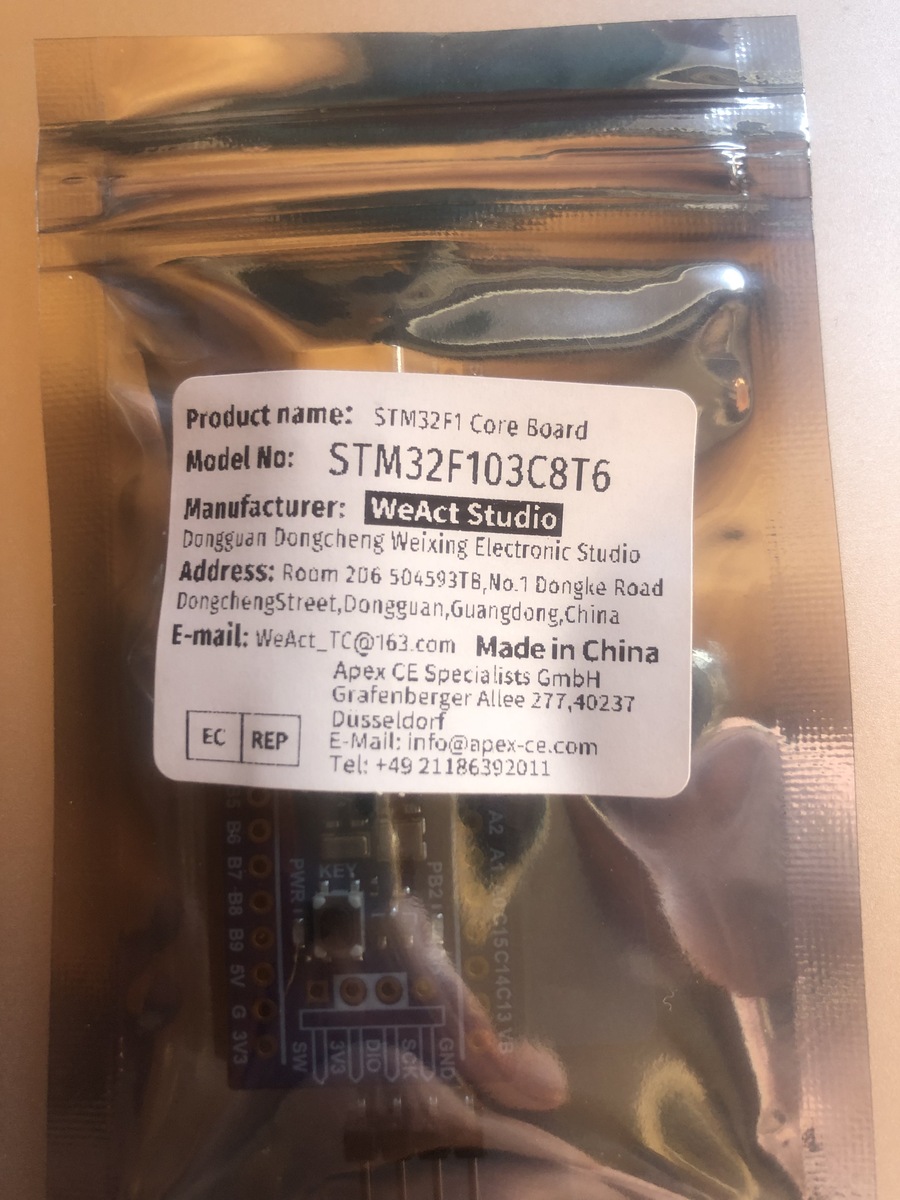
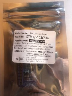
Verpackung eines STM32F1 Core Board
Product name: STM32F1 Core Board Model No: STM32F103C8T6 Manufacturer: WeAct Studio Dongguan Dongcheng Weixing Electronic Studio Address: Room 206 504593TB, No.1 Dongke Road Dongcheng Street, Dongguan, Guangdong, China
in „neuere BluePill (WeAct) I2C1 will nicht“ · Mikrocontroller und Digitale Elektronik · · Fotos
-
 Bild
Bild
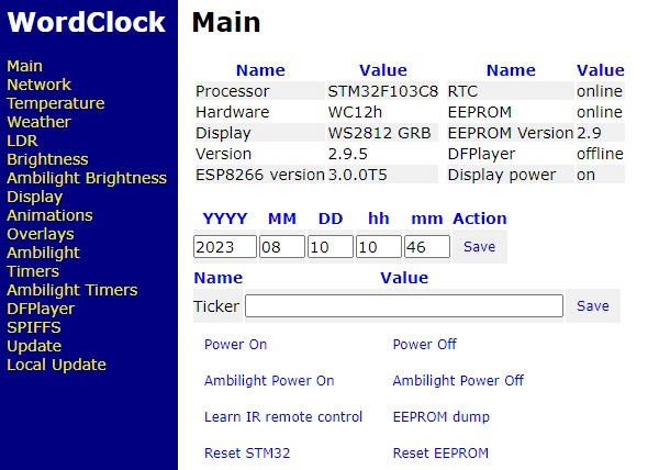
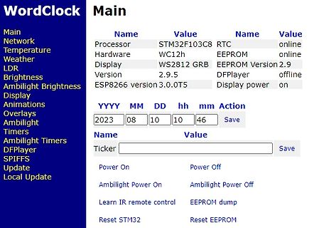
Webinterface einer WordClock mit Systemstatus und Einstellungen
WordClock Main Main Name Value Name Value Processor STM32F103C8 RTC online Hardware WC12h EEPROM online Display WS2812 GRB EEPROM Version 2.9 Version 2.9.5 DFPlayer offline ESP8266 version 3.0.0T5 Display power on YYYY MM DD hh mm Action 2023 08 10 10 46
in „WordClock mit WS2812“ · Projekte & Code · · Screenshots
-
PDF
project.pdf
E E E E E E E E E B B C D A D 1uF P V V P P P P P P P P P P P P P P P P P P P P V V C33 100nF 6 7 8 9 0 1 2 3 4 5 6 7 8 9 0 1 2 3 4 5 6 7 8 9 0 STM32F407VGT6 +5V +5V P2 +5V P3 2 2 2 2 3 3 3 3 3 3 3 3 3 3 4 4 4 4 4 4 4 4 4 4 5 M1OUTA 1 M2OUTA 1 R21 2 R23 2 +3.3V 3.3k 3.3k GND C38 P10 ENC1B 3 8 ENC2B
in „Schaltplan so richtig? STM32F407VG“ · Mikrocontroller und Digitale Elektronik ·
-
PDF
project.pdf
E E E E E E E E E B B C D A D 1uF P V V P P P P P P P P P P P P P P P P P P P P V V C33 100nF 6 7 8 9 0 1 2 3 4 5 6 7 8 9 0 1 2 3 4 5 6 7 8 9 0 STM32F407VGT6 +5V +5V P2 +5V P3 2 2 2 2 3 3 3 3 3 3 3 3 3 3 4 4 4 4 4 4 4 4 4 4 5 M1OUTA 1 M2OUTA 1 R21 2 R23 2 +3.3V 3.3k 3.3k GND C38 P10 ENC1B 3 8 ENC2B
in „Schaltplan so richtig? STM32F407VG“ · Mikrocontroller und Digitale Elektronik ·
-
 Bild
Bild
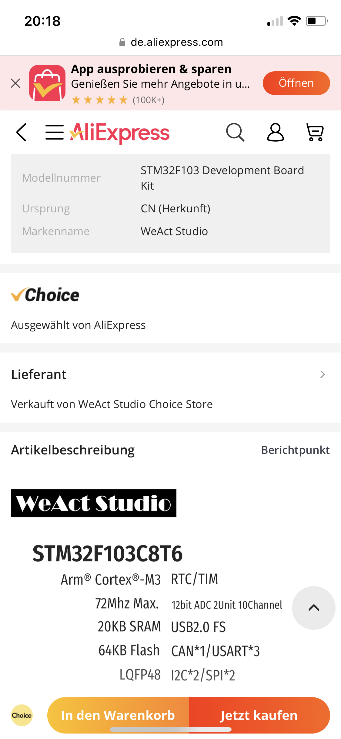
AliExpress Produktseite STM32F103 Development Board
de.aliexpress.com App ausprobieren & sparen Genießen Sie mehr Angebote in u... Öffnen Modellnummer STM32F103 Development Board Kit Ursprung CN (Herkunft) Markenname WeAct Studio Choice Ausgewählt von AliExpress Lieferant Verkauft von WeAct Studio Choice Store Artikelbeschreibung Berichtpunkt WeAct Studio STM32F103C8T6 Arm® Cortex®-M3 RTC/TIM 72Mhz Max. 12bit ADC 2Unit 10Channel 20KB SRAM USB2.0 FS 64KB Flash CAN*1/USART*3 I2C*2/SPI*2 LQFP48 In den Warenkorb Jetzt kaufen
in „neuere BluePill (WeAct) I2C1 will nicht“ · Mikrocontroller und Digitale Elektronik · · Screenshots

-
 Bild
Bild
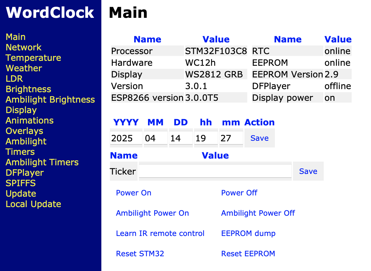
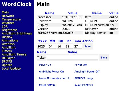
Webinterface einer WordClock Steuerung
Animations Overlays Ambilight Timers Ambilight Timers DFPlayer SPIFFS Update Local Update Processor STM32F103C8 Hardware WC12h Display WS2812 GRB Version 3.0.1 ESP8266 version 3.0.0T5 RTC online EEPROM online EEPROM Version 2.9 DFPlayer offline Display power on YYYY MM DD hh mm Action 2025 04 14 19 27
in „WordClock mit WS2812“ · Projekte & Code · · Screenshots
-
Datei
mmc_stm32f1.c
for SPI1 Busy Flag cleared */ d = SPI1->DR; buff[1] = d; buff[0] = d >> 8; SPI_8Bit(); } #if _USE_WRITE /* Send multiple byte */ #pragma GCC push_options #pragma GCC optimize ("-O0") static void xmit_spi_multi ( const uint8_t *buff, /* Pointer to the data */ uint32_t btx)
in „STM32F103 diskio.c für Chan FatFs SD Karten Treiber“ · Projekte & Code ·
-
Datei
mmc_stm32f1.c
) == SET); /* Wait for SPI1 Busy Flag cleared */ d = SPI1->DR; buff[1] = d; buff[0] = d >> 8; SPI_8Bit(); } #if _USE_WRITE /* Send multiple byte */ #pragma GCC push_options #pragma GCC optimize ("-O0") static void xmit_spi_multi ( const uint8_t *buff, /* Pointer to the data */ uint32_t btx)
in „STM32F103: Problem mit ChanFat und SD karte“ · Mikrocontroller und Digitale Elektronik ·
-
Datei
mmc_stm32f1.c
) == SET); /* Wait for SPI1 Busy Flag cleared */ d = SPI1->DR; buff[1] = d; buff[0] = d >> 8; SPI_8Bit(); } #if _USE_WRITE /* Send multiple byte */ #pragma GCC push_options #pragma GCC optimize ("-O0") static void xmit_spi_multi ( const uint8_t *buff, /* Pointer to the data */ uint32_t btx)
in „STM32F103 diskio.c für Chan FatFs SD Karten Treiber“ · Projekte & Code ·
-
PDF
stm32_magic_eye2.pdf
SPI1_MISO G G 2 PA6 TP1 4 9 PA7 23 SPI1_MOSI TestPoint GNDD GNDD 41 D57 D58 D59 D60 D61 D62 D63 D64 PA8 LED LED LED LED LED LED LED LED PA9 42 +3V3 +5VA GNDD 43 GNDD L07 GNDD PA10 44 PA11 D PA12 45 D XTAL1 5 46 SWDIO PD0 PA13 XTAL2 6 PD1 PA14 49 SWCLK C18 100n +5V +5VA 54 50 10µ C23 L2 PD2 PA15 STM32F103RCTx
in „STM32F103 und I2S Probleme“ · Mikrocontroller und Digitale Elektronik ·
-
Datei
hse_auto_clock.c
/* Automatische Erkennung von ext. HSE-Takt für STM32F7xx. Michael Nowak 2019-05-07 www.mino-elektronik.de */ #include "stm32f7xx.h" #define SOLLFREQUENZ_MHZ 216 // Vorgabewert #define PLL_M 16 // für internen HSI Takt #define PLL_Q 7 #define PLL_N (
in „STM32F429-Discovery Recycling: 90 MHz Frequenzzähler mit TFT“ · Projekte & Code ·
-
Datei
ws2812_stm32f4.c
#include <stdio.h> #include "stm32f4xx.h" #include "ws2812_stm32f4.h" #include "delay.h" // externally writable color data for all leds volatile uint32_t ws2812_framebuffer[WS2812_NR_LEDS]; // local buffer for timer/dma, one byte per
in „[STM32] Binäruhr bzw 12x4 RGB LED Display mit WS2812“ · Projekte & Code ·
-
Datei
usb.c
/* ST STM32F103C8T6: USB als COM Port betreiben */ #include "StdTypes.h" #include "STM32F103all.h" #include "usb.h" /* die Transfer-Puffer für zeichenweises In und Out über den USB */ #define txLen 256 char UsbTxBuf
in „USB CDC von Stefan Frings und WS“ · Mikrocontroller und Digitale Elektronik ·
-
Datei
Beispiel.txt
wf_PA2 (out2_altfu) /* TXD2 normaler Kommunikationsport */ #define wf_PA3 (in_gpi) /* RXD2 9600 Bd 8N1 an DSUB9, */ #define wf_PA4 (out2_altfu) /* ? (DAC) */ #define wf_PA5 (out2_altfu) /* ? (DAC) */ #define wf_PA6 (in_pupd) /* ? */ #define wf_PA7 (in_pupd) /* ? an Messerleiste */ #define wf_PA8 (out50
in „STM32F103C8 Platformprojekt mit Display, FATFS und Examples“ · Projekte & Code ·
-
Datei
stm32-timer.h
_IC2F_by8_6 (TIM_CCMR1_IC2F_3 ) #define TIM_CCMR1_IC2F_by8_8 (TIM_CCMR1_IC2F_3 |TIM_CCMR1_IC2F_0) #define TIM_CCMR1_IC2F_by16_5 (TIM_CCMR1_IC2F_3 |TIM_CCMR1_IC2F_1 ) #define TIM_CCMR1_IC2F_by16_6 (TIM_CCMR1_IC2F
in „CMSIS und GNU Support“ · Mikrocontroller und Digitale Elektronik ·
-
Datei
ili9341.c
3; ++num_samples; } HAL_SPI_Transmit(lcd->spi_hal, (uint8_t*)sleep, sizeof(sleep), __SPI_MAX_DELAY__); ili9341_spi_touch_release(lcd); // restore SPI clock to maximum for TFT // TODO: based on STM32G4, which is clocked at 170MHz. support other chips. //MODIFY_REG
in „STM32U575 und ILI9341 SPI DMA Problem“ · Mikrocontroller und Digitale Elektronik ·
-
Datei
main.c
#include "stm32f4xx.h" #include "main.h" int main(void) { SystemInit(); StartClock(); PortConfig(); Test(); while(1) { TestLoop(); } } //#include "tm_stm32f4_usb_vcp.h" //#include "defines.h" //int main(void){ // uint8_t c; // SystemInit(); /* Initialize USB VCP */ // TM_USB_VCP_Init(); //while (1) { /* USB configured OK, drivers OK */ // if (TM_USB_VCP_GetStatus() == TM_USB_VCP_CONNECTED) { /* Turn on GREEN led */
in „Datenerfassung, Analog -> USB / RS232“ · Mikrocontroller und Digitale Elektronik ·
-
Datei
CAN1_0.ino
// -------------------------------------- Umbenenen der STM Pins // Bliotheken //------------------------------------------------------------------------------------------------------------Testweise auskommentiert #include <assert.h> #include "stm32f103.h" /
in „Arduino Blue Pill & CAN mit SN65HVD230“ · Mikrocontroller und Digitale Elektronik ·
-
Datei
irmpconfig.h
--------------------------------------------------------------- * Change hardware pin here for ARM STM32 *--------------------------------------------------------------------------------------------------------------------------------------------------- */ #elif defined (ARM_STM32) // use C13 as IR input on STM32 # define IRMP_PORT_LETTER C # define IRMP_BIT_NUMBER 13 /*------------------------------------------------------------------------------------------------------------------------------------------
in „IRMP - Infrared Multi Protocol Decoder“ · Projekte & Code ·
-
Datei
irmpconfig.h
--------------------------------------------------------------- * Change hardware pin here for ARM STM32 *--------------------------------------------------------------------------------------------------------------------------------------------------- */ #elif defined (ARM_STM32) // use C13 as IR input on STM32 # define IRMP_PORT_LETTER C # define IRMP_BIT_NUMBER 13 /*------------------------------------------------------------------------------------------------------------------------------------------
in „IRMP - Infrared Multi Protocol Decoder“ · Projekte & Code ·
-
Datei
config.c
/* Konfiguration für das Testboard mit STM32F302RBT6 */ #include "StdTypes.h" #include "STM32F302xB.h" #include "startup.h" #include "config.h" /**************** symbolische Port-Pin Eigenschaften **************************/ /* Pro Port gibt
in „Welcher Timer ist für die Dauer eines Ticks im SysTick verantwortlich?“ · Mikrocontroller und Digitale Elektronik ·
-
Datei
config.c
/* Konfiguration für das Testboard mit STM32F302RBT6 */ #include "StdTypes.h" #include "STM32F302xB.h" #include "startup.h" #include "config.h" /**************** symbolische Port-Pin Eigenschaften **************************/ /* Pro Port gibt
in „stm32f103 hse clock“ · Mikrocontroller und Digitale Elektronik ·
-
PDF
extended_serial_library.pdf
Konstante, Variable, Konstruktoren und Methoden von extendedSerial beschrieben. Konstante constexpr uint8_t black = 0; constexpr uint8_t blue = 1; constexpr uint8_t green = 2; constexpr uint8_t cyan = 3; constexpr uint8_t red = 4; constexpr uint8_t magenta = 5; constexpr uint8_t brown = 6; constexpr uint8_t grey = 7; constexpr uint8_t darkgrey = 8; constexpr uint8_t lightblue = 9; constexpr uint8_t lightgreen = 10; constexpr uint8_t lightcyan = 11; constexpr uint8_t lightred = 12; constexpr uint8_t lightmagenta = 13; constexpr uint8
in „Arduino und struct gefallen sich nicht !“ · Mikrocontroller und Digitale Elektronik ·