-
PDF
10_1536_SE_P_Circuit_Breaker_Catalog.pdf
SERIES 1536 MINIATURE PROTECTION AMBIENT-TEMPERATURE COMPENSATED PER FO R M A N C E DATA Three-Pole High Performance Interrupting Capacity 1,000A at 205V, 400 Hz., three-phase symmetrical fault Three-Phase Protection 1,000A at 120V, 400 Hz., single-phase fault Common trip mechanism
in „[V] verkaufe 10 Stück ECE Einbausicherungen 7,5A 3 polig“ · Markt ·
-
PDF
2287522.pdf
calculate the minimum and maximum constant current values that can be programmed for the outputs for a chosen R ext 900 mV 1 IO_LED_MIN = --R------4-minimum constant current (4) ext I _LED_MAX = 255 I _LED_MIN = --------------- (5) O O R ext 4 For a given IREFx setting, I _LED = IREFx -
in „[V] 10St. NXP PCA9955 16-channel Fm+ I2C-bus 57 mA/20 V constant current LED driver SSOP28 (10€)“ · Markt ·
-
PDF
2287522.pdf
calculate the minimum and maximum constant current values that can be programmed for the outputs for a chosen R ext 900 mV 1 IO_LED_MIN = --R------4-minimum constant current (4) ext I _LED_MAX = 255 I _LED_MIN = --------------- (5) O O R ext 4 For a given IREFx setting, I _LED = IREFx -
in „[V] 10St. NXP PCA9955 16-channel Fm+ I2C-bus 57 mA/20 V constant current LED driver SSOP28“ · Markt ·
-
PDF
ISBN_3-9800725-0-9.pdf
2143 148 CQW14 95 DL 3400 141 HA 2144 148 8 Typ Seite Typ Seite Typ Seite HD 1075, 1076 144 MAN 81 A 150 TIL41 . . 50 98 HD 1077, 1078 144 MAN 82 A 150 TIL 78 92 HD 1105 145 MAN 83A 150 TIL 302 151 HD 1106 TIL 303 145 MAN 84A 150 151 HD 1107 145 MAN 3610 A 150 TIL 304 151 HD 1108 145 MAN 3620 A 150
-
PDF
FTP.pdf
LA R G EC A P A C IT A N C EA LU M IN U MELEC TR O LYTICC A P A C ITO R S Inverter-use screw terminal, 85C @Ideal for inverter smoothing capacitors such as Electric Vehicle, Hybrid Car, etc. @Endurance with ripple
in „Mein erster ovaler Elko“ · Analoge Elektronik und Schaltungstechnik ·
-
PDF
opa376.pdf
) 900 a A n 90 t t n e r 800 e 80 C R t d e 700 o 70 s n u o Q m 60 600 o C 50 500 -50 -25 0 25 50 75 100 125 150 -50 -25 0 25 50 75 100 125 150 Temperature (°C) Temperature (°C) Figure 7. Figure 8. QUIESCENT
in „technische anforderungen“ · Analoge Elektronik und Schaltungstechnik ·
-
PDF
Photodiode.pdf
( T = 25 °C, Normlicht A, T = 2856 K) A Characteristics (T A= 25 °C, standard light AT = 2856 K) (contÕd) Bezeichnung Symbol Wert Einheit Description Symbol Value Unit Leerlaufspannung, EV = 1000 lx V O 360 (≥ 280) mV Open-circuit
in „Spitzenwertdetektor Laserstrahlmessung“ · Analoge Elektronik und Schaltungstechnik ·
-
PDF
datasheetFilter.pdf
CHARACTERISTICS (CFWC455CZ2) 0 120 0 0 4 10 10 8 20 20 95 12 30 30 ) . ) ) d 16 e d 40 d 40 ( µ ( ( i . i i a 20 70 . a 50 a 50 n . n n t 24 G t 60 t 60 A A A 70 28 70 45 32 80 80 90 36 90 100 40 20 100 200 300 400 500 600 700 800 900 1000 430 455 480 405 455 505 Frequency (kHz) Frequency (kHz) Frequency (kHz
in „Superhet mit einer Loop-Antenne=Empangsspule für KW“ · HF, Funk und Felder ·
-
PDF
Uref_mit_Filter.pdf
noise by Com 10/1 (from 600 Vp-p to 60 Vp-p). 4 The conventional circuit, shown in Figure 1, uses a single- pole RC filter and a buffer amplifier. One problem with this 88 circuit is that leakage current through the filter capacitor, C FIGURE 2. Voltage Reference with Improved Filter. 1 flowsthroughR
in „Einen LM7815 rauscharm betreiben“ · Analoge Elektronik und Schaltungstechnik ·
-
PDF
Athlet_BCH6L2560_SCH.pdf
1 2 42 1 DpS X2-2 C34 200 edr 22-23-2021 2 k IC1 pS X2-1 R 1 R47 7812DT U1 1 0 200 1 2 4 R1 BQ77PL900DL R 1 VI VO , T A R50 U6 8 , + A 200 GND TP30 65678 P 1 R C1 1 CPOUT CHG 48 3 5 T 5 G C 2 47 1000 4 P - R4 3 NC_2 PACK 46 R43 Q15 T + A 4 CP4 PMS 45 200 GND R17 2 TP11 IRFS3306S - C2 5 CP3 NC 44 13
in „Bosch Athlet 25,2 V Akku 7 Stück Tauschen“ · Analoge Elektronik und Schaltungstechnik ·
-
PDF
5521f.pdf
Voltage vs LO Power –32 10 26 10 25 –33 IIP3 P 8 IIP3 24 8 22 ( –34 B –35 85°C ) 6 23 ) 6 25°C 18 A I B–36 –40°C ) –40°C D ) P ( d NF N d 4 85°C 22 ( G–37 C 4 14 S (C 25°C B K 25°C G E G 2 –40°C 21 ) E–38 G L 2 10 U G C –39 E 0 20 –40 G C d 0 6 ) –2 19 –41 85°C –42 –2 2 –4 18 850 900 950 1000 1050
in „Anpassung Differenztialeingang LT5521“ · HF, Funk und Felder ·
-
PDF
MC55_Seite30-31.pdf
Software /EMERGOFF controlled Serial interfaces ASC0 and ASC1 Undefined Inactive Active ca. 300ms ca. 900ms For details please see Chapter 3.3.1.2 Figure 3: Power-on by ignition signal In a battery operated MC55/56 application, the duration of the /IGT signal must be 1s minimum when the charger is connected
in „Siemens MC55“ · Mikrocontroller und Digitale Elektronik ·
-
PDF
DPX202690DT-4049A2.pdf
746 MHz 20.88 dB ] 15 B 15 2690 MHz 16.83 dB [ 824 MHz 22.85 dB n 20 n 20 960 MHz 43.72 dB t t u 25 a 25 e 30 n 30 A t 35 A 35 40 40 45 45 50 50 0 500 1000 1500 2000 2500 3000 0 500 1000 1500 2000 2500 3000 Frequency[MHz] Frequency[MHz] Lo-Band Port S21 Hi-Band Port S31 0 Insertion Loss 0 Insertion Loss
in „Antennendiplexer 915Mhz / 2,4Ghz“ · Analoge Elektronik und Schaltungstechnik ·
-
Datei
main.c
#include <stdint.h> #include "stm32f3xx.h" // delay loop without using a timer // for 48MHz, Latency 1, gcc optimizer enabled void delay_ms(uint32_t msec) { for (uint32_t j=0; j<6000UL*msec; j++) { __NOP(); } } // Change system clock to 48 MHz using 8 MHz crystal // Called
in „STM32 läuft mit Debugger schneller als er soll“ · Mikrocontroller und Digitale Elektronik ·
-
PDF
Delevan-4212.pdf
4 1–1 1 1⁄2 170 320 375 — — — -5 1–2 2 — 525 600 — 600 — -6 1–2 2 240 520 480 — — — -7 1–4 3 — 950 900 — 600 — -8 1–4 3 400 800 550 — — — *Complete part # must include series # PLUS the dash # Physical Parameters Inches Millimeters Length 0.374 to 0.414 9.50 to 10.51 Diameter 0.216 to 0.256 5.48 to 6.35 Lead Size AWG #24 TCW 0.0185 to 0.0215 0.47 to 0.55 A 0.12 Max. 3.05 Max. B 1.10 Min. 28.0 Min. Impedances measured on HP 4191A Impedance Analyzer. High resistivity ferrite material eliminates the need to insulate windings. LeadWire Plated copper Actual
-
PDF
VAR-DT6CUSTOMBOARD_SCH_V1_1_Doc_V1_2.pdf
A 1 VCCA VCCB 16 12 CBUS0 USB_DEBUG_DP 1 4 USB_DEBUG_DP_C 4 ID 2 15 11 L104 5 3 1DIR 1OE# 14 5 CBUS1 D D D 3V3OUT MCZ1210AH900L2T GND 4 2DIR 2OE# 13 14 CBUS2 P N N 9 4 3 J102 S S 3 UART1_RX 5 1A1 '0'-
-
PDF
SFH229.pdf
Unit SFH 229 SFH 229 FA Fotoempfindlichkeit Spectral sensitivity VR = 5 V, Normlicht/standard light A, S 28 (≥ 18) — nA/Ix T = 2856 K, VR = 5 V,λ = 950 nm, Ee= 1 mW/cm 2 S — 20 (≥ 10.8) A Wellenlänge der max. Fotoempfindlichkeit λS max 860 900 nm Wavelength of max. sensitivity Spektraler Bereich der
in „Fototransistor im Auto“ · Analoge Elektronik und Schaltungstechnik ·
-
PDF
EFS10.pdf
Feuchte [%] 8 4 6 Temp. 20 30 40 50 60 70 80 90 9 [°C] + : 10 9000 2500 740 220 72,00 25,80 9,50 3,72 a F 15 6364 1803 543 166 55,64 20,94 8,07 3,26 - 6 20 4500 1300 398 125 43,00 17,00 6,85 2,85 8 8 25 2890 900 270 81 33,00 13,00 5,30 2,20 4 6 30 2100 670 210 66 25,50 10,20 4,28 1,85 9 + 35 1652 530 168
in „Feuchtesensor EFS10 Temperaturkompensation“ · Analoge Elektronik und Schaltungstechnik ·
-
PDF
156545-da-01-de-Feuchtesensor_EFS10.pdf
Feuchte [%] 8 4 6 Temp. 20 30 40 50 60 70 80 90 9 [°C] + : 10 9000 2500 740 220 72,00 25,80 9,50 3,72 a F 15 6364 1803 543 166 55,64 20,94 8,07 3,26 - 6 20 4500 1300 398 125 43,00 17,00 6,85 2,85 8 8 25 2890 900 270 81 33,00 13,00 5,30 2,20 4 6 30 2100 670 210 66 25,50 10,20 4,28 1,85 9 + 35 1652 530 168
in „Funktion einer Messschaltung“ · Analoge Elektronik und Schaltungstechnik ·
-
Datei
main.c
(i==CCR2) LPM3; } } interrupt (TIMERA0_VECTOR) Timer_A0(void) //CCRO interrupt vector nicht benutzt! { //TAR_high++; } interrupt (TIMERA1_VECTOR) Timer_A1(void) //TAIV interrupt vector { static unsigned int CCR_start=0; static unsigned int CCR_stop=0; static
in „MSP430 Timer_A Overflow und PWM“ · Mikrocontroller und Digitale Elektronik ·
-
PDF
CY2890-F02-datasheet-v2.4.pdf
characteristics PARAMETER SYMBOL CONDITION MIN. TYP. MAX. UNIT REMARK Input low current IL No pull up or 1 1 A pull down No pull up or Input high current IIH pull down 1 1 A Tri state leakage current IOZ 10 10 A Logic input low voltage VIL CMOS 0.3VDD V Note 1 Schmitt input low voltage VSIL CMOS 0.3VDD V Note
in „Display ansteuerung“ · Mikrocontroller und Digitale Elektronik ·
-
PDF
VGA-Timing-2.pdf
following table. (It is usually required to measure under the following condition. condition:If=130mA,Ta=25ˆʶ2ˆ) Parameter Symbol Min. Typ. Max. Unit Remark LED voltage V L ʵ (22) ʵ V LEDcurrent range V L ʵ (130) ʵ mA Value for one channel Number ofcircuit channel ʵ (2) ʵ [Note 1] Lamp powerconsumption
in „Frage zu VGA: Wann beginnt V-sync“ · PC Hard- und Software ·
-
PDF
elv.pdf
Abgleichschritt eine einfache 5-W-Kfz-Glühlampe gut geeignet. M MitdemDrehimpulsgeberistderAusgangsstromauf0,300 A 3 x1 (±0,5 mA) einzustellen. M3 6 ZumAbspeichern des eingestellten Wertes wird die „Enter“- x5 Taste kurz betätigt, sobald im Display „Memory“ angezeigt wird. Abgleichschritt4 IndermittlerenDisplayzeileerscheintnun1,900Aundrechts
in „Problem mit ELV Netzteil Bausatz PPS 5630“ · Mikrocontroller und Digitale Elektronik ·
-
Bild
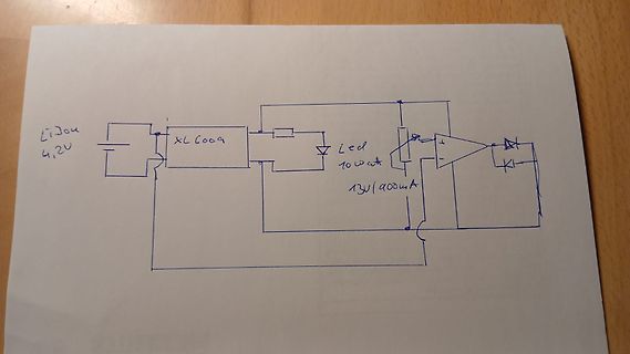
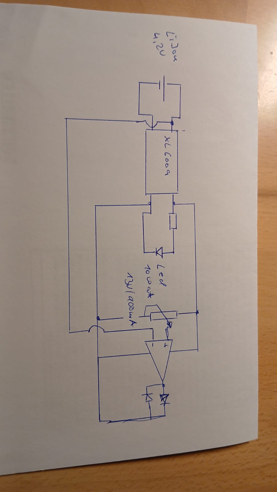
Handgezeichneter Schaltplan einer LED-Treiberbeschaltung
LiIon 4,2V XL6009 Led 10 watt 13V/900mA
in „Spannungsmessung LiIon“ · Analoge Elektronik und Schaltungstechnik · · Fotos
-
Bild
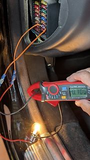
Messung mit Stromzange an einer Glühbirne
True RMS 2000 Counts 0.100 900A AC/DC Maxi Clamp Meter SELECT/FC ZERO HOLD/V
in „Interner Kurzschluss Steuergerät?“ · Fahrzeugelektronik · · Fotos
-
PDF
steps.pdf
900 800 700 r600 W C D A500 400 300 200 0 2 4 6 8 10 Abstand in mm
in „UV-Laserdrucker II“ · Platinen ·
-
Bild
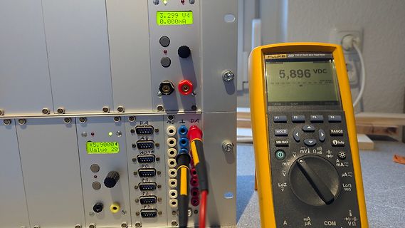
Labornetzteil und Fluke Multimeter
3.299 V1 0.000mA FLUKE 289 TRUE RMS MULTIMETER 5,896 VDC +5,900V Value 20
in „Verkaufe: c't lab mit verschiedenen Modulen“ · Markt · · Fotos
-
PDF
Magnetventile_-_ISO15407VSVA_DE.pdf
-/Pneumatikventile, ISO 15407-1 Peripherieübersicht Einzelmontage 6 5 7 6 4 5 7 3 2 1 8 9 aC aE aB aJ aE aA aD aF aE aF Typ Kurzbeschreibung ➔ Seite/Internet 1 Verbindunsleitung SIM-…-4-GD Dose gewinkelt sim 2 Verbindunsleitung SIM-…-4-GD Dose gerade sim 3 Steckdose SEA-M12-4WD gewinkelt 70
in „Mikrocontroller an 24V mit Optokopller?“ · Mikrocontroller und Digitale Elektronik ·
-
PDF
LTC6102.pdf
300µV V OSift 25nV/°C 1µV/°C 1µV/°C 1µV/°C 0.5µV/°C 1.5µV/°C 1.5µV/°C 0.5V/°C 0.5V/°C IBIASaximum 3nA 170nA 40nA 40nA 25µA 170nA 170nA 20µA 10µA Gain R-SET R-SET R-SET R-SET R-SET R-SET R-SET 8V/V PIN-SET PSSRMinimum 120dB 118dB 106dB 106dB 100dB 110dB 110dB 120dB 105dB Comment Zero Drift V to 105V Lowest
in „Strommessschaltung High Side“ · Analoge Elektronik und Schaltungstechnik ·
-
Datei
Haussteuerung_V27.txt
To 47 Z = I - 40 Sb_a.z = Sb(i + 1) Next Shiftout Dat , Clk , Sb_a , 1 , 8 End If If P(3) > 32 Then For I = 32 To 39 Z = I - 32 Sb_a.z = Sb(i + 1) Next Shiftout Dat , Clk , Sb_a , 1 , 8 End If If P(3) > 24 Then For I = 24
in „Mega644 reset“ · Mikrocontroller und Digitale Elektronik ·
-
PDF
4_wellen.pdf
Tabelle1 1000 900 Spalte A 800 Spalte B Spalte C 700 Spalte D Spalte E 600 500 400 300 200 100 0 Seite 1
in „Puls aus Sinuswelle herausrechnen“ · Mikrocontroller und Digitale Elektronik ·
-
Datei
sect30.inc
Bus collision, Start/stop condition .lword dummy_int ; INT1 .glb _timerir .lword _timerir ; Timer A1 .lword dummy_int ; USB EP0 .lword dummy_int ; Timer A2 .lword 0FF900H ; UART1 receive/ACK/SSI receive .lword dummy_int ; UART0/UART2 Bus collision, Start/stop condition .lword dummy_int ; UART0 receive
in „M16C debuggen - keine Verbindung möglich“ · Mikrocontroller und Digitale Elektronik ·
-
Bild
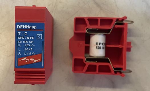
DEHNgap Überspannungsableiter und Einsatzmodul
DEHNgap T - C SPD / N-PE C No. 900 134 Uc 255 V~ In 20 kA Up ≤ 1,5 kV DEHN EPCO 500 00
in „Funktion Überspannungsschutz testen“ · Haus & Smart Home · · Fotos
-
PDF
RAC03-SCR_277.pdf
Constant Max. 3Watt Number Range Voltage Current Efficiency Current Range* Capacitive (VAC) (VDC) (mA) (%) (mA) Load Single RAC03-3.3SCR/277* 85-305 3.3 900 69 950-1200 22000 RAC03-05SCR/277* 85-305 5 600 71 650-850 10000 Output RAC03-12SCR/277* 85-305 12 250 76 280-370 1500 RAC03-24SCR/277* 85-305 24
in „Suche Trafo - So klein wie möglich“ · Analoge Elektronik und Schaltungstechnik ·
-
Bild
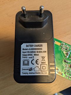
Netzteil mit Typenschild
BATTERY CHARGER Model: JLH283000900G Input: 100-240VAC 50-60Hz 40W Output: 30VDC 900mA Polarity: CE Intertek GS Yueqing Jielahua Electric Co., Ltd.
in „Steckernetzteil 30V DC Fehlersuche Defekt“ · Analoge Elektronik und Schaltungstechnik · · Fotos
-
Bild
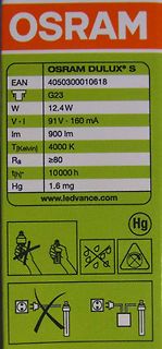
Verpackung einer OSRAM DULUX S Leuchtstoffröhre
OSRAM DULUX S EAN 4050300010618 G23 12.4W 91V · 160 mA 900 lm 4000 K ≥80 10000 h 1.6 mg Hg www.ledvance.com Hg
in „Leuchtstoffröhrenfrage“ · Analoge Elektronik und Schaltungstechnik · · Fotos
-
Bild
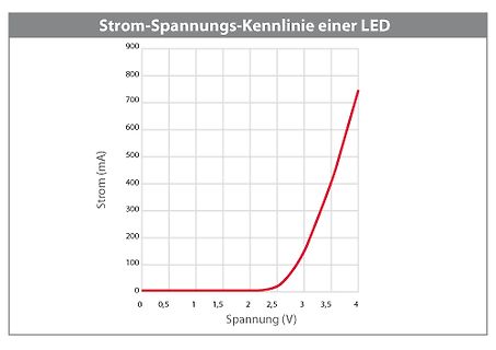
Strom-Spannungs-Kennlinie einer LED
Strom-Spannungs-Kennlinie einer LED 900 800 700 600 500 400 300 200 100 0 Strom (mA) 0 0,5 1,5 2 2,5 3 3,5 4 Spannung (V)
in „LED - Leuchte“ · Haus & Smart Home · · Diagramme
-
PDF
ESB_Lastabwurf_HV_Batterie.pdf
Lastabwurf beim Betreib einer HV-Batterie HV+ ~900A Gleichstrom Batterieprüfstand ~400V Gleichspannung 15V 0V Funktionsgenerator C 5V di/dt G IGBT Treiber E 0V IC GND HV-
in „Abschalten eines Gleichstromkreis bei 400V und 900A“ · Analoge Elektronik und Schaltungstechnik ·
-
Bild
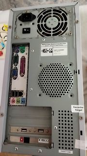
Rückseite eines Computergehäuses
Made by Fujitsu Siemens Computers GmbH 900-240 V ~ 50 Hz 4,0 A Made in Germany SNR 3724050881 Pf. Nr. 50-720 Scanned © D1500 Garantie-Siegel 10600372280 CE CB CX618
in „Festplatten zu verschenken“ · Markt · · Fotos
-
Bild
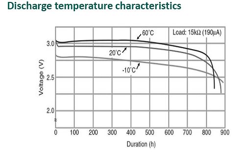
Diagramm der Entladetemperatur-Charakteristik
Discharge temperature characteristics 60°C Load: 15kΩ (190µA) 20°C -10°C Voltage (V) 3.0 2.5 2.0 0 100 200 300 400 500 600 700 800 900 Duration (h)
in „Bei welcher Leerlaufspannung ist eine CR 2025 entladen?“ · Offtopic · · Diagramme
-
Datei
Bosch_Athlet_DIY_240619.ino
switch pos 2 #define TURBO 5 // on switch pos 3 #define PRESSURE 8 // pressure sensor #define IBAT A3 // IBAT from BQ77PL900 monitors charge (=positive) und brush (=negative) currents #define VBAT A7 // VBAT from BQ77PL900 monitors batt voltages #define BQWRITE 16 // EEPROM BQ write (enable = HIGH)
in „Bosch Athlet 25,2 V Akku 7 Stück Tauschen“ · Analoge Elektronik und Schaltungstechnik ·
-
Bild
Elektronisches Bauteil mit Kabeln und Beschriftung
0,33uF+2x3'900pF,1Y+2x3mH 58 095 000 01H 250V - 5.5A MF25/085/21 0710 565-3 1055 br- Netz bl- ge
in „Entstörfilter - Jura Impressa 500 - Kaffemaschine“ · Analoge Elektronik und Schaltungstechnik · · Fotos
-
PDF
SEMIKRON_DataSheet_SKT_100_01236311.pdf
SKT 100 I = 175 A (maximum value for continuous operation) VRSM V RRM,V DRM TRMS V V TAV= 100 A (sin. 180;cT = 85 °C) 500 400 SKT 100/04 D 900 800 SKT 100/08 D 1300 1200 SKT 100/12 E 1500 1400 SKT 100/14 E 1700 1600 SKT
in „Thyristor Steuerung mit Teensy 4.0“ · Analoge Elektronik und Schaltungstechnik ·
-
Datei
MINO.BAS
CHR$(32) 109 REM - MOVEMENT 110 LOCATE B,C:PRINT CHR$(138) 120 LOCATE X,Y:PRINT CHR$(128) 150 GET A 155 REM 158 IF A<>0 THEN @ X,Y:? CHR$(32) 160 IF A=54 THEN X=X+1 161 IF A=51 THEN X=X+1:Y=Y+1 162 IF A=56 THEN Y=Y-1 163 IF A=11 THEN Y=Y-1 164 IF A=57 THEN X=X+1:Y=Y-1 165 IF A=55 THEN X=X-1:Y=Y-1 166 IF A=52 THEN X=X-1 167 IF A=49 THEN X=X-1:Y=Y+1 168 IF A=50 THEN Y=Y+1 170 IF A=27 THEN END 172 IF A=0 THEN GOTO 150 173 @ 0,4: ? " " 174 REM 175 LIMIT X,14,22 176 LIMIT Y,10,20 177 F=A((Y-10)*9+(X-14)) 178
in „AVR Tiny Basic Computer mit ATMega1284“ · Projekte & Code ·
-
Bild
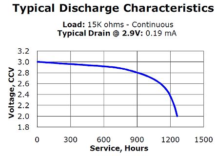
Diagramm der Entladecharakteristik einer Spannungsquelle
Typical Discharge Characteristics Load: 15K ohms - Continuous Typical Drain @ 2.9V: 0.19 mA Voltage, CCV 3.2 3.0 2.8 2.6 2.4 2.2 2.0 1.8 0 300 600 900 1200 1500 Service, Hours
in „Bei welcher Leerlaufspannung ist eine CR 2025 entladen?“ · Offtopic · · Diagramme
-
Bild
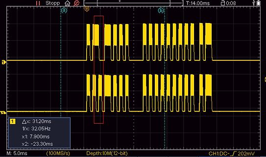
Oszilloskop-Messung eines digitalen Signals
Stopp T:14.00ms 0:08 a b 1 Δx: 31,20ms 1/x: 32,05Hz x1: 7.900ms x2: -23,30ms M: 5.0ms (100MS/s) Depth:10M(12-bit) CH1:DC- 202mV
in „Welcher FernbedienungsCode ?“ · Mikrocontroller und Digitale Elektronik · · Oszi-Bilder
-
Bild
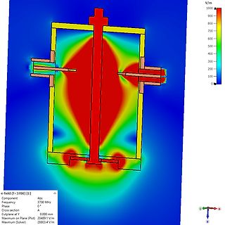
Simulation der elektrischen Feldstärke E-Feld
V/m 1000 900 800 700 600 500 400 300 200 100 0 e-field (f=3700) [1] Component Abs Frequency 3700 MHz Phase 0° Cross section A Cutplane at Y 0.000 mm Maximum on Plane (Plot) 20489.1 V/m Maximum (Solver) 28803.4 V
in „Hilfe bei Software CST Studio Suit 2024 gesucht“ · HF, Funk und Felder · · Screenshots
-
Bild
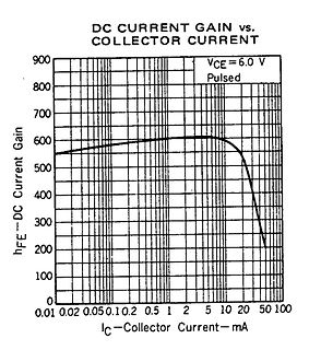
Diagramm der DC-Stromverstärkung über dem Kollektorstrom
DC CURRENT GAIN vs. COLLECTOR CURRENT 900 800 VCE=6.0 V 700 Pulsed 600 hFE-DC Current Gain 500 400 300 200 100 0 0.01 0.02 0.05 0.1 0.2 0.5 1 2 10 20 50 100 IC-Collector Current-mA
in „Stromfolger für Spannungssteuerung von OTAs“ · Analoge Elektronik und Schaltungstechnik · · Diagramme
-
PDF
Uzebox-rev-D1.pdf
0 1 2 3 4 5 6 7 8 9 10 11 12 13 14 VCC U12 VCC GND 7 5V U8 6 J7 D2 LM2940T-5 5V A NC2 A 5 LINE VREG NC1 VOLTAGE DATA 4 1N4001 C11 COMMON C12 HDR1X2 470nF 47uF VCC VCC LATCH 3 5V 5V DC IN (9-12V) CLK 2 VCC 1 C16 10uF B SNESConnector 100nF VSS C8 C6 C7 C9 B Player 2 COMMON C17 10uF
in „Atmega644 übertakten“ · Mikrocontroller und Digitale Elektronik ·
-
Datei
taster.htm
__DRAKA_CAT6.html">Crossover DRAKA UC900 CAT6</A></TD></TR> <TR valign=top><TD valign=top align=left><A class="Sitemap" href="Crossover_Ecolan_SFTP_CAT5e.html">Crossover ECOLAN</A></TD></TR> <TR valign=top><TD valign=top align=left><A class
in „Pull up Widerstand Arduino“ · Mikrocontroller und Digitale Elektronik ·