
-
Datei
main.c
2007-03-29 17:07:19Z cs $ */ #define F_CPU 12000000L /* evaluation board runs on 4MHz */ #include <avr/io.h> #include <avr/interrupt.h> #include <avr/pgmspace.h> #include <avr/wdt.h> #include "usbdrv.h" #include "oddebug.h" /* ----------------------- hardware I/O abstraction ------------------------
in „V-USB: HIDKeys ignoriert ersten Tastendruck“ · Mikrocontroller und Digitale Elektronik ·
-
Datei
Original.asm
...`..>...' rjmp avr0553 ; 0531 C021 0A62 '!......`..>.....' avr0532: in r16, ?0x07? ; 0532 B107 0A64 '.....`..>.......' andi r16, 0xF0 ; 0533 7F00 0A66 '...`..>.........' ori r16, 0x0C ; 0534 600C 0A68 '.`..>..........
in „32 kHz kompatibler Bootloader gesucht“ · Mikrocontroller und Digitale Elektronik ·
-
Datei
Liste.txt
SHIFT/STORAGE REGISTER WITH 3-STATE OUTPUTS 25x 907550022 ???????? 25x 907550013 ??????? 25x 48128/la28l22 ????? 8x tm4116-20nl ??????? 8x mk4116n2???????? 15x cdp1833ce Upverter ?? 10x cf72300x n 8740 SMD ???? 36x STE 081164 10X 4050 HEX-Non Inverting Buffer 10x MC14093B Quad 2-Input NAND Schmitt Trigger
-
PDF
CentiPad_Flyer_0601.pdf
max. 500mA) max. 1MBit/s CPU: AT91RM9200,ARM9 @ 180MHz Ethernet: - 10/100MBit/s HD/FD PHY SDRAM: 32/64MByte SDRAM - automatische CrossOver Erkennung DataFlash: 2/4MByte serielles DataFlash, Serial Interface: - TTYD: debug port, RS232 RX/TX, bootfähig bootfähig MiniSD: MiniSDCard-Sockel on Board, - TTY0
-
Datei
prog.asm
----------------------------------------------------------- ; prog.asm: programmer for programming AVR flash and EEPROM ; ; author: Gerhard Paulus ; company: GNOM SOFT GmbH, Dresden ; date: August 2002 ; ; This software implements the programming protocoll specified in ; Atmels application note avr910
-
Datei
clock.c
#include "main.h" #include "clock.h" #include <avr/io.h> #include <avr/interrupt.h> //Die Uhrzeit wird in folgenden Variablen gespeichert volatile unsigned char ss = 0; //Globale Variable für die Sekunden volatile unsigned char mm = 0; //Globale Variable
in „DCF auf INT0“ · Mikrocontroller und Digitale Elektronik ·
-
Datei
mw_clock.c
#include "main.h" #include "clock.h" #include <avr/io.h> #include <avr/interrupt.h> //--// #include <stdbool.h> #include <util/delay.h> //--// //Die Uhrzeit wird in folgenden Variablen gespeichert volatile unsigned char ss = 0; //Globale Variable für
in „DCF auf INT0“ · Mikrocontroller und Digitale Elektronik ·
-
Datei
Test_PWM.c
/* * PWM.c * * Created: 02.06.2015 20:39:46 * Author: Laptop */ #include <avr/io.h> #include <avr/pgmspace.h> #define F_CPU 8000000UL #include <util/delay.h> #define INVERT_PWM (0 << COM1A0) #define TASTERPORT PINC #define TASTERBIT PINC5 const uint16_t pwmtable_16[256] PROGMEM
in „HW PWM zum LED dimmen“ · Mikrocontroller und Digitale Elektronik ·
-
Datei
font6x8.h
Date: 12.02.2004 * * * *********************************************/ #include <inttypes.h> #include <avr/pgmspace.h> #ifndef FONT6X8_H #define FONT6X8_H #define FONT6X8_WIDTH 6 #define FONT6X8_HEIGHT 8 static uint8_t __attribute__ ((progmem)) Font6x8[] = { 0x00, 0x00, 0x00, 0x00, 0x00, 0x00, // "(space
in „Displaytech 64128A an ATMega8“ · Mikrocontroller und Digitale Elektronik ·
-
Datei
font6x8.h
Date: 12.02.2004 * * * *********************************************/ #include <inttypes.h> #include <avr/pgmspace.h> #ifndef FONT6X8_H #define FONT6X8_H #define FONT6X8_WIDTH 6 #define FONT6X8_HEIGHT 8 static uint8_t __attribute__ ((progmem)) Font6x8[] = { 0x00, 0x00, 0x00, 0x00, 0x00, 0x00, // "(space
in „STM32 C was passiert da?“ · Mikrocontroller und Digitale Elektronik ·
-
Datei
deinterleave.h
#ifndef DEINTERLEAVE_H #define DEINTERLEAVE_H #include <inttypes.h> //#include <avr/pgmspace.h> const __flash uint8_t even_odd_bits[] = { 0, 1, 16, 17, 2, 3, 18, 19, 32, 33, 48, 49, 34, 35, 50, 51, 4, 5, 20, 21, 6, 7, 22, 23, 36, 37, 52, 53, 38, 39, 54, 55, 64, 65, 80, 81, 66, 67,
in „AVR/ATmega uint32_t Deinterleaving optimieren“ · Mikrocontroller und Digitale Elektronik ·
-
PDF
man_gcc.pdf
attiny84a", "attiny841", "attiny85", "attiny861", "attiny861a", "attiny87", "attiny88", "at86rf401". "avr3" "Classic" devices with 16@tie{}KiB up to 64@tie{}KiB of program memory. mcu@tie{}= "at43usb355", "at76c711". "avr31" "Classic" devices with 128@tie{}KiB of program memory. mcu@tie{}= "atmega103",
in „avr-g++: external linkage von const/PROGMEM Symbol.“ · Mikrocontroller und Digitale Elektronik ·
-
Datei
i2c.c
#include "i2c.h" #include "usart.h" #include <stdint.h> #include <stdio.h> #include <avr\io.h> //---------------------------------------------------------------------------------- //*** PRIVATE VARIABLEN ************************************************************ //--------------------
in „AVR I2C Master Receiver kein ACK“ · Mikrocontroller und Digitale Elektronik ·
-
Datei
crc16.c
#include <avr/io.h> // CRC16 CCITT X^16 x^12 + x^5 + 1 static uint16_t crc_table [256] = { 0x0000, 0x1021, 0x2042, 0x3063, 0x4084, 0x50a5, 0x60c6, 0x70e7, 0x8108, 0x9129, 0xa14a, 0xb16b, 0xc18c, 0xd1ad, 0xe1ce, 0xf1ef
in „Floppy MFM Decoder selber bauen AVR ATmega Assembler Beispiele FDD Diskette“ · Projekte & Code ·
-
Datei
MakeTime_t.c
#include <avr/io.h> #include <avr/pgmspace.h> #include <avr/interrupt.h> uint32 hardwareTimeZone = 3600; // Offset in Sekunden uint32 hardwareDaylightOffset = 3600; // Sommerzeit Offset in Sekunden const char dayTab[12] PROGMEM = { 31, 28, 31, 30, 31, 30, 31, 31, 30, 31, 30, 31 }; uint8_t isDST( uint8_t mday, uint8_t mon, uint16_t year ); uint8_t calcWeekday(uint8_t day, uint8_t month, uint16_t year); int16_t dayOfTheYear(uint8_t day,
in „Berechnung Datum + Uhrzeit + Sommerzeit“ · Projekte & Code ·
-
Datei
main.c
1307, USA. ----------------------------------------------------------------------------*/ #include <avr/io.h> #include "config.h" #include "usart.h" #include "networkcard/enc28j60.h" #include "networkcard/rtl8019.h" #include "stack.h" #include "timer.h" #include "wol.h" #include "httpd.h" #include "cmd.h
in „AVR für wenig Geld im LAN“ · Mikrocontroller und Digitale Elektronik ·
-
Datei
main.c
Systematischer Fehler der Baudrate grösser 1% und damit zu hoch! #endif #include <inttypes.h> #include <avr/io.h> #include <util/delay.h> #include <avr/pgmspace.h> // global variables uint16_t pwmtable_16[256] PROGMEM = {0, 1, 1, 1, 1, 1, 1, 1, 1, 2, 2, 2, 2, 2, 2, 2, 2, 2, 2, 2, 2, 3, 3, 3, 3, 3, 3, 3, 4
in „ATMega32 USART 16MHz (Pollin-Board)“ · Mikrocontroller und Digitale Elektronik ·
-
PDF
PWM_Controller_Manual.pdf
mit 0 initialisieren. PWM- Controller Pinout Reset, ISP, Clock und PowerSupply sollten entsprechend AVR Hardware Design Considerations AVR042 beschaltet werden. Wobei ISP- nicht zwingend notwendig ist. Ich würde ISP- empfehlen, da an der Firmware weiterhin fleißig gefeilt wird ☺ Crystal als ClockSource
in „PWM- Controller 18- Kanal TWI- Bus Proj.“ · Projekte & Code ·
-
PDF
XPLAIN_Shematic.pdf
TILLER D NORWAY Date: 08.05.2009 15:10:18 PAGE: 1 of 5 Document number: A08-0551 Revision: A TITLE: AVR1907: Xplain evaluation board, Top-Level Xplain.SchDoc 1 2 3 4 5 6 7 8 1 2 3 4 5 6 7 8 2 3 1 1 T T JTAG/PDIInterface PQ2 NTC_EN XMEGA_PDI_DATA XMEGA_PDI_DATA XMEGA_RESET_PDI_CLK XMEGA_RESET_PDI_CLK PQ3
in „Xplain: Schaltplan gesucht“ · Mikrocontroller und Digitale Elektronik ·
-
Datei
lcd_tools.h
PC0-PC3 = D4-D7 * R/W ist n.c. * * 03/2005 Florian Schäffer, http://www.blafusel.de * */ #include <avr/io.h> #include <avr/delay.h> #define delay(us) _delay_loop_2 (((F_CPU/4000)*us)/1000) // wartet µs // Enable-Leitung toggeln void lcd_flash_e () { PORTC = PORTC | ( 1<<DDC5 ) ; // Enable = HIGH delay(1); // kurz warten, damit Flanke entsteht PORTC = PORTC & ~( 1<<DDC5 ) ; // Enable = LOW delay(64); // Warten, bis der durch Enable angelegte Befehl hoffentlich verarbeitet wurde } // Kommando oder Zeichen an Display senden: rs=0 => Kommando, rs=1 => Zeichen void lcd_write (uint8_t data, uint8_t
in „LCD Problem mit blafusel´s Routinen“ · Mikrocontroller und Digitale Elektronik ·
-
 Bild
Bild
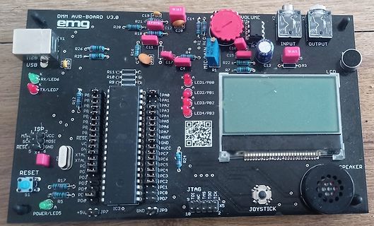
DMM AVR-BOARD V3.0 Leiterplatte mit LCD und Joystick
DMM AVR-BOARD V3.0 emg X1 USB LED6 RX/ LED7 TX R11 C19 R16 C12 C20 C15 R21 R18 C11 R25 R26 R12 R10 R9 R1 R2 R3 R24 R17 R5 R4 R13 R14 R15 R19 R20 R22 R23 R27 R28 R29 R30 R31 R32 R33 R34 R35 R36 R37 R38 R39 R40 R41 R42 R43 R44 R45 R46 R47 R48 R49 R50 R51 R52 R53 R54 R55 R56 R57 R58 R59 R60 R61 R62 R63 R64 R65 R66 R67 R68 R69 R70 R71 R72 R73 R74 R75 R76 R77 R78 R79 R80 R81 R82 R83 R84 R85 R86 R87 R88 R89 R90 R91 R92 R93 R94 R95 R96 R97 R98 R99 R100 R101 R102 R103 R104 R105 R106 R107 R108 R109 R110 R111
in „Suche Unterlagen zum DMM AVR-BOARD V3.0 der TU Braunschweig“ · Mikrocontroller und Digitale Elektronik · · Platinenfotos
-
Datei
Steu4414.hex.asm
; reassembly of "Steu4414.hex" ; created by ReAVR 2.4 ; at 2013/06/07 - 23:44:59 ; for Atmel AVR assembler ;--------------------------------------- .cseg .org 0x0000 ;--------------------------------------- ; byte constants: ; .equ k00 = 0x00 ; .equ
in „Gerät mit AT90S4414 retten“ · Mikrocontroller und Digitale Elektronik ·
-
Datei
oled_2313demo.c
12 | PB0 - AIN0 - PCINT0 GND | 10 11 | PD6 - ICP +-------------+ */ #include <stdint.h> #include <avr/io.h> #include <avr/pgmspace.h> #include <util/delay.h> /* ------------------------------------------------------------ Konfiguration ------------------------------------------------------------ */
in „I2C Display einfache Frage“ · Mikrocontroller und Digitale Elektronik ·
-
Datei
iomxx0_1.h
define CLKPS2 2 #define CLKPS1 1 #define CLKPS0 0 /* Reserved [0x62..0x63] */ #define PRR0 _SFR_MEM8(0x64) #define PRTWI 7 #define PRTIM2 6 #define PRTIM0 5 #define PRTIM1 3 #define PRSPI 2 #define PRUSART0 1 #define PRADC 0 #define __AVR_HAVE_PRR0 ((1<<PRADC)|(1<<PRUSART0)|(1<<PRSPI)|(1<<PRTIM1)|(1<<PRTIM0)|(1<<PRTIM2)|(1<<PRTWI)) #define __AVR_HAVE_PRR0_PRADC #define __AVR_HAVE_PRR0_PRUSART0 #define __AVR_HAVE_PRR0_PRSPI #define __AVR_HAVE_PRR0_PRTIM1 #define __AVR_HAVE_PRR0_PRTIM0 #define __AVR_HAVE_PRR0_PRTIM2 #define __AVR_HAVE_PRR0_PRTWI
in „Tasterverarbeitung mit dem ARDUINO“ · Mikrocontroller und Digitale Elektronik ·
-
Datei
Adc.asm
000,001,003,007,00c,00f,011, ; ;***** Hardware-Pins ********************************************************** ; ; AVR-Contr. ADC-Input ; ----------------------------- ; PA0 Pin 40 ; PA1 Pin 39 ; PD6 Selbsthaltung ; PD7 18V-Erzeuger ; PC6,7 32768Hz Quarz Pin 28,29 fuer Timing ; ; ; AVR-Contr. LCD-Display ; ---------
in „AD-Wandler spinnt . . .“ · Mikrocontroller und Digitale Elektronik ·
-
Datei
Uhr.c
// Firmware AVR_Interface // Autor: Rahul Ghose // Stand: 16.März 2006 // Hohe Taktfrequenz! #include <iom64.h> #include <intrinsics.h> /* ====================================================================== */ /
-
PDF
ATtiny804-06-07-1604-06-07-DataSheet-DS40002312A.pdf
ATtiny804/806/807/1604/1606/ 1607 ® tinyAVR 0-series Introduction ® ® The ATtiny804/806/807/1604/1606/1607 are members of the tinyAVR 0-series of microcontrollers, using the AVR processor with hardware multiplier, running at up to 20 MHz, with
in „ATTINY804 RTC bekomme ich nicht hin“ · Mikrocontroller und Digitale Elektronik ·
-
Datei
uart.c
UCSR1A #define UART1_CONTROL UCSR1B #define UART1_DATA UDR1 #define UART1_UDRIE UDRIE1 #elif defined(__AVR_ATmega64__) || defined(__AVR_ATmega128__) /* ATmega with two USART */ #define ATMEGA_USART0 #define ATMEGA_USART1 #define UART0_RECEIVE_INTERRUPT SIG_UART0_RECV #define UART1_RECEIVE_INTERRUPT SIG_UART1
in „[AVR-GCC] makefile SRC und #include“ · Mikrocontroller und Digitale Elektronik ·
-
Datei
FloppyMusik.c
/* * FloppyMusik.c * * Created: 11.07.2014 08:09:28 * Author: chaoskind * Programm zur Steuerung von 3,5" Floppy Laufwerken, um Töne zu erzeugen * * * Pinbelegung(Active Low) 0/1 * * PD1 = Floppy An/Aus * PD2 = Diskmotor An/Aus * PD3 = Richtung Lesekopf
in „Musikalisches Diskettenlaufwerk“ · Mikrocontroller und Digitale Elektronik ·
-
Datei
DHT11_22.c
#include <stdlib.h> #include <avr/io.h> #include <stdio.h> #include <stdlib.h> #include <avr/interrupt.h> #include <util/delay.h> #include <stdbool.h> #include <string.h> #include "DHT11+22.h" /**************************************
in „Fehler bei einfacher Integer-Division?“ · Mikrocontroller und Digitale Elektronik ·
-
PDF
SerialComInstruments_Doku.pdf
Numerischen Funktion: setNumInstrument(1, Messwert); //Instrument 1 == Vertikal-Meter } Beispiel in LunaAVR ' Beispiel Funktion für SerialComInstruments ' avr.device = atmega328p avr.clock = 16000000 avr.stack = 100 uart.baud = 115200 uart.Send.enable Dim i, f as single Dim s as string s = "Hallo MC" do for
in „Projekt: Virtuelle Instrumente an serielle Schnittstelle“ · Projekte & Code ·
-
Datei
SIG_INTERRUPT0.txt
#include <avr/io.h> #define send r24 //Übergabe Register an serout #define Ist r5 //Arbeitsregister #define Soll r6 //Arbeitsregister #define Chk r7 //Arbeitsregister #define temp r25 //Arbeitsregister .stabs "",
in „Register in Assembler Interruptfunktionen?“ · Mikrocontroller und Digitale Elektronik ·
-
PDF
MIK-k05-AVR_uc.pdf
AVR – RISC – Mikrocontroller Kapitel 5 5 Die Zeitgeber/Zähler (Timer/Counter) 5.1 Der Vorteiler (Prescaler) und die Timer-Steuerlogik Nachfolgende Abbildung zeigt den Aufbau der Steuerlogik der AVR - Familie
in „Warum komme ich beim Auswärten des ADC's nur bis 25% ?“ · Mikrocontroller und Digitale Elektronik ·
-
Datei
clock.c
/*####################################################################################### AVR DCF77 Clock Copyright (C) 2005 Ulrich Radig #######################################################################################*/ #include "clock.h" #include "../Global.h" #include "../gui/main_gui.h" #include <avr/io.h> #include <avr/interrupt.h> //Bitzähler für RX Bit volatile unsigned char rx_bit_counter = 0; //64 Bit für DCF77 benötigt werden 59 Bits volatile unsigned long long dcf_rx_buffer = 0; //Hilfs Sekunden
in „xmega und dcf von u. radig“ · Mikrocontroller und Digitale Elektronik ·
-
PDF
Private_Entruempelung_des_Bastel-Lagers.pdf
TM-T88IIP • Mit paralleler Schnittstelle • Inkl. Papierrollen • 30€ #64 – HOSAFE IP-Kamera • Full-HD • Inkl. IR LEDs (für Nachtsicht) • Inkl. Netzteil und POE-Injektor • 25€ #65 – Honeywell T ürgong • DC917S • Mit eigenen MP3-Melodien und Blinkanzeige • Inkl. Klingeltaster
-
PDF
Private_Entruempelung_des_Bastel-Lagers_V2.pdf
TM-T88IIP • Mit paralleler Schnittstelle • Inkl. Papierrollen • 30€ #64 – HOSAFE IP-Kamera • Full-HD • Inkl. IR LEDs (für Nachtsicht) • Inkl. Netzteil und POE-Injektor • 25€ #65 – Honeywell T ürgong • DC917S • Mit eigenen MP3-Melodien und Blinkanzeige • Inkl. Klingeltaster
-
PDF
Private_Entruempelung_des_Bastel-Lagers_V3.pdf
TM-T88IIP • Mit paralleler Schnittstelle • Inkl. Papierrollen • 30€ #64 – HOSAFE IP-Kamera • Full-HD • Inkl. IR LEDs (für Nachtsicht) • Inkl. Netzteil und POE-Injektor • 25€ #65 – Honeywell T ürgong • DC917S • Mit eigenen MP3-Melodien und Blinkanzeige • Inkl. Klingeltaster
-
PDF
Private_Entruempelung_des_Bastel-Lagers_V4.pdf
TM-T88IIP • Mit paralleler Schnittstelle • Inkl. Papierrollen • 30€ #64 – HOSAFE IP-Kamera • Full-HD • Inkl. IR LEDs (für Nachtsicht) • Inkl. Netzteil und POE-Injektor • 25€ #65 – Honeywell T ürgong • DC917S • Mit eigenen MP3-Melodien und Blinkanzeige • Inkl. Klingeltaster
-
Datei
nokia_lcd.c
fonts support. 2003-03-20 - v0.3: Serialization optimized, 2003-05-27 - v0.4: runable Version for WinAVR Author: Guido Fischer; http://www.ispf.de --------------------------------------------------------------------------------------------------*/ #include <avr/io.h> #include <avr/pgmspace.h> #include
in „Nokia LCD: Problem mit SBI“ · Mikrocontroller und Digitale Elektronik ·
-
Datei
display_lib.c
#include <avr/io.h> #include <util/delay.h> #include "display_lib.h" #include <math.h> // CHAR | ASCII-DEC const int FONT[95][5] ={ 0x00, 0x00, 0x00, 0x00, 0x00, // SPACE 32 0x00, 0x00, 0x5F, 0x00, 0x00, // ! 33
-
PDF
PWM_Controller_Manual.pdf
internal RC-Oscillator. PWM- Controller Pinout Reset, ISP, Clock und PowerSupply sollten entsprechend AVR Hardware Design Considerations AVR042 beschaltet werden. Wobei ISP- nicht zwingend notwendig ist. Ich würde ISP- empfehlen, da an der Firmware weiterhin fleißig gefeilt wird ☺ Crystal als ClockSource
in „PWM- Controller 18- Kanal TWI- Bus Proj.“ · Projekte & Code ·
-
Datei
RGB-Fader.c
#include <avr/io.h> //Grundfunktionen #ifndef F_CPU //Vordefinieren für delay.h #define F_CPU 1000000UL //Definition von F_CPU in Herz #endif #include <util/delay.h> //Warteschleifen /* Portbelegung: PD0 =Blau PD1
-
Datei
RGB-Fader.c
#include <avr/io.h> //Grundfunktionen #ifndef F_CPU //Vordefinieren für delay.h #define F_CPU 1000000UL //Definition von F_CPU in Hertz #endif #include <util/delay.h> //Warteschleifen /* Portbelegung: PD0 =Blau PD1
-
Datei
dcfm8.c
/* ATMega8 */ /* DCF-Dekoder und Temperaturfühler für 2 DS1621 mit Ausgabe auf Display*/ #include <avr/signal.h> #include "delay.h" #include <stdio.h> #include <avr/io.h> #include "lcd-routines.h" #include <avr/interrupt.h> #include <avr/pgmspace.h> #include <stdlib.h> #include <string.h> //#include
in „Funk-uhr über AVR Programmieren mit DCF01“ · Mikrocontroller und Digitale Elektronik ·
-
PDF
ATTINY_3216_DB.pdf
ATtiny3216/3217 tinyAVR 1-series Introduction ® ® The ATtiny3216/3217 are members of the tinyAVR 1-series of microcontrollers, using the AVR processor with hardware multiplier, running at up to 20 MHz, with 32 KB Flash, 2
in „Attiny 3216 QTouch Funktion“ · Mikrocontroller und Digitale Elektronik ·
-
Datei
HeizgV20.c
*************** Project : Heizung ATmega32 Version : V2.0 Date : 15.09.2010 ATMEGA32 Compiler: WIN-AVR Status des Programms: 29.11.2006 Fehler im Taktgenerator (Uhr ging falsch) 15.07.2009 umgeschrieben auf Win_avr Compiler Fleury's LCD und UART Bibliothek, Ergänzung einer Offsetkompensation für die
in „Heizungssteuerung mit ATMEGA 32“ · Mikrocontroller und Digitale Elektronik ·
-
Datei
mega128RFA1.h
// CodeVisionAVR V2.0 C Compiler // (C) 1998-2009 Pavel Haiduc, HP InfoTech S.R.L. // (C) 2010 Christian Erle, IBE, added / changed to ATmega128RFA1 // I/O registers definitions for the ATmega128RFA1 #ifndef _MEGA1281
in „ATmega128RFA1“ · Mikrocontroller und Digitale Elektronik ·
-
Datei
sensorhub.asm
.nolist .include "/home/lukas/Dokumente/AVR/includes/m48def.inc" .list ;************************************************************** ;Notizen ;************************************************************** ;sudo avrdude -c avrispmkII -P usb
in „Controller fällt in (anscheinend) RESET“ · Mikrocontroller und Digitale Elektronik ·
-
PDF
Dokumentation.pdf
...................................................................................................28 Quellen und Dank.......................................................................................................28 Erklärung....................................................................
in „Vielen Dank!“ · Mikrocontroller und Digitale Elektronik ·
-
Datei
akkuload.asm
Schleifenanfang als Rücksprungadresse auf den Stapel push rmp ldi rmp,HIGH(loop) push rmp ; Prüfe die 64 Hz Tick Flagge von Timer 0 sbrc rFlg,b64Hz ; ein Tick? rjmp Tick64Hz ; lese Tasten und werte sie aus ; Prüfe ob 32 Messzyklen komplett sind und 4 Sekunden vorüber sind sbrc rFlg,b32m ; Prüfe 32 Messungen
in „Asssembleprogramm für Mega16 auf Mega8535 anpassen, Sprungweite "call" und "jmp"“ · Mikrocontroller und Digitale Elektronik ·
